Trusted Business
Verified & Licensed
Virus Free Files
100% Safe Downloads
Secure Payment
SSL Protected
Instant Delivery
Available Immediately
Sale!


Hyster Forklift S40 50F service manual – PDF DOWNLOAD
Original price was: $92.95.$32.95Current price is: $32.95.
Hyster Forklift S40 50F service manual
Instant PDF Download
Available immediately
Save to Your Device
Download & keep forever
Antivirus Scanned
100% virus-free
Trusted Worldwide
175,000+ customers
Description
Hyster Forklift S40 50F service manual
File Details:
Hyster Forklift S40 50F service manual
Language : English
Pages : 405
Size : 12.2 MB
Downloadable : Yes
Format : PDF
HYSTER FORKLIFT S40 50F SERVICE MANUAL – PDF DOWNLOAD:
Image Preview:
Description:
Hyster Forklift S40 50F service manual
- GENERAL This section has a description and the repair procedures for the alternator with a voltage regulator as part of the alternator. CAUTION When using an arc welder, always disconnect the ground lead from the lift truck battery to prevent alternator or battery damage.
- Attach the welding ground clamp as close to the weld area as possible to prevent welding current from damaging the bearings. The diodes and resistors in the electrical system can be damaged if the following cautions are not followed: • Do not disconnect the battery when the engine is running. The voltage surge can damage the diodes and resistors in the electrical system. • Do not disconnect an electric wire before the engine is stopped and the switches are “OFF”. •
- Do not cause a short–circuit by connecting the electric wires to the wrong terminals. Make sure a correct identification is made of the wire before it is connected. • Make sure a battery is the correct voltage and polarity before it is connected. • Do not check for current flow by making a spark because the electronic components can be damaged. NOTE: Information on alternators manufactured outside the United States is in the SRM (service repair manual) sections for lift trucks that use those alternators
- . DESCRIPTION (See FIGURE 1. and FIGURE 2.) NOTE: For this SRM section, the alternators are in two groups, Type A and Type B. The two types are very similar, but the Type A alternators have a set of three diodes (diode set) as well as the diode bridge. The Type B alternator has zener diodes as part of the diodes in the diode bridge. This alternator does not have a diode set, but does have an additional fan inside the rear housing. The basic operation of both types is very similar.
- The alternator generates an alternating current when the engine is running. The alternator is either ON or OFF. The alternator generates maximum current when it is ON and no current when it is OFF. The regulator switches the alternator between ON and OFF to get the average current needed to charge the battery. Alternator output is directly changed by engine speed and rotor field current. The alternating current is changed to a direct current by the diode bridge inside the alternator
Table of Contents:
Hyster Forklift S40 50F service manual
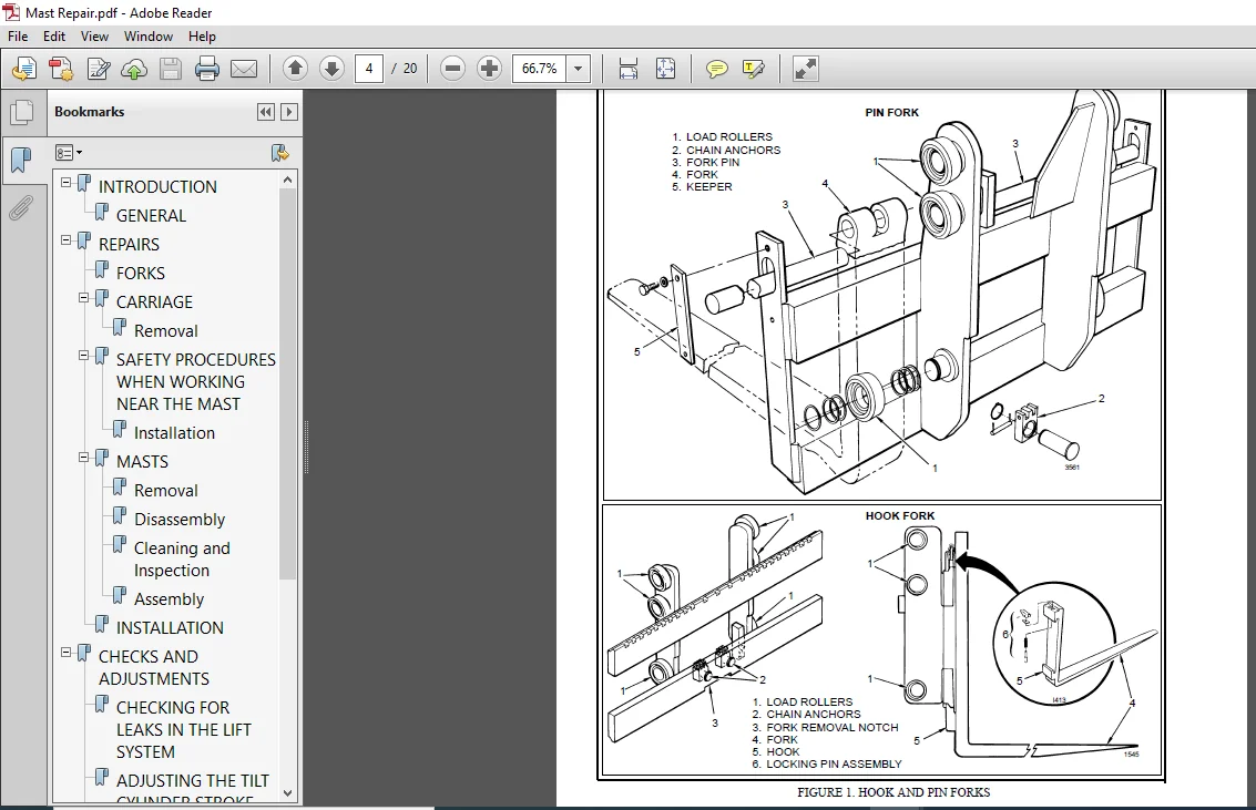
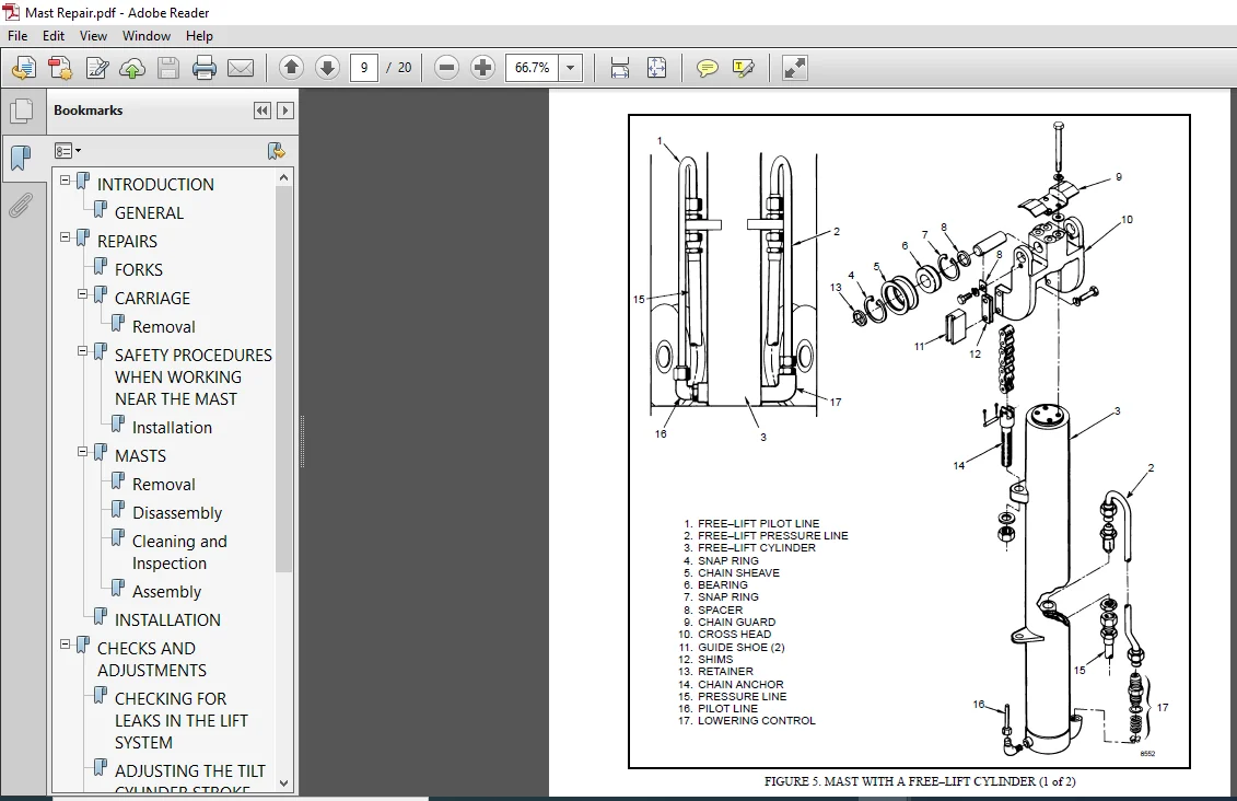
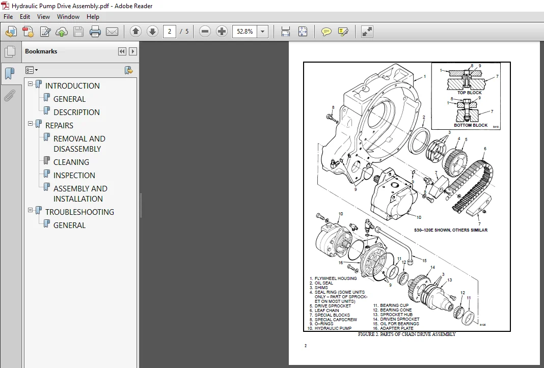
INTRODUCTION.............................................................................................  1
	GENERAL..............................................................................................  1
	DESCRIPTION..........................................................................................  1
REPAIRS..................................................................................................  3
	GENERAL..............................................................................................  3
	REMOVAL AND DISASSEMBLY (Type A).....................................................................  3
	CLEANING.............................................................................................  3
	ASSEMBLY (Type A)....................................................................................  4
	REMOVAL AND DISAASSEMBLY (Type B)....................................................................  6
	CLEANING.............................................................................................  8
	ASSEMBLY (Type B)....................................................................................  8
	INSTALLATION (Type A and Type B).....................................................................  9
CHECKS AND ADJUSTMENTS...................................................................................  9
	GENERAL..............................................................................................  9
	CHECK THE ALTERNATOR FOR LOW OUTPUT (Type A or Type B)............................................... 10
	CHECK THE ALTERNATOR FOR HIGH OUTPUT (Type A or Type B).............................................. 11
	CHECK THE CIRCUIT FOR THE BRUSHES.................................................................... 13
		Delco Alternators................................................................................ 13
		Motorola Alternators............................................................................. 13
	CHECK THE DIODES..................................................................................... 13
	CHECK THE DIODE BRIDGE............................................................................... 13
		Delco and Leece–Neville Alternators.............................................................. 13
		Motorola Alternators............................................................................. 13
	CHECK THE FIELD WINDING FOR THE ROTOR................................................................ 14
	CHECK THE WINDINGS IN THE STATOR..................................................................... 14
	CHECK THE VOLTAGE REGULATOR.......................................................................... 15
TROUBLESHOOTING.......................................................................................... 15
INTRODUCTION............................................................................................. 16
	GENERAL.............................................................................................. 16
	DESCRIPTION AND OPERATION............................................................................ 16
REPAIRS.................................................................................................. 20
	CLEANING PROCEDURES.................................................................................. 20
	REMOVAL AND DISASSEMBLY.............................................................................. 20
	INSPECTION........................................................................................... 21
	ASSEMBLY............................................................................................. 22
CHECKS AND ADJUSTMENTS................................................................................... 24
	ADJUSTING THE SERVICE BRAKES......................................................................... 24
	ADJUSTING THE PARKING BRAKE.......................................................................... 24
	REMOVING THE AIR FROM THE BRAKE SYSTEM............................................................... 24
	ADJUSTING THE SERVICE BRAKE PEDAL.................................................................... 25
TROUBLESHOOTING.......................................................................................... 26
COOLING SYSTEM........................................................................................... 28
	INTRODUCTION......................................................................................... 28
	DESCRIPTION.......................................................................................... 28
	RADIATOR............................................................................................. 28
	RADIATOR CAP......................................................................................... 28
	THERMOSTAT........................................................................................... 28
	WATER PUMP........................................................................................... 29
	FAN AND FAN SHROUD................................................................................... 29
REPAIRS.................................................................................................. 29
	COOLING SYSTEM CHECKS................................................................................ 29
		Exhaust Leaks.................................................................................... 29
	RADIATOR............................................................................................. 29
		Checks........................................................................................... 29
		Cleaning The Radiator............................................................................ 29
		Drain The Cooling System......................................................................... 31
		Fill The Cooling System.......................................................................... 31
	WATER PUMP........................................................................................... 31
		Checks........................................................................................... 31
	THERMOSTAT........................................................................................... 32
		Checks........................................................................................... 32
	FAN AND FAN SHROUD................................................................................... 32
TROUBLESHOOTING.......................................................................................... 33
FIGURE 1. SCHEMATIC FOR THE LIFT AND TILT SYSTEM......................................................... 34
FIGURE 2. ELECTRICAL SCHEMATIC........................................................................... 36
FIGURE 3. STEERING SYSTEM AND TRANSMISSION SCHEMATIC..................................................... 37
INTRODUCTION............................................................................................. 38
	General.............................................................................................. 38
	Description.......................................................................................... 38
REPAIRS.................................................................................................. 39
	Removal.............................................................................................. 39
	Installation......................................................................................... 40
	Axle Housing For S30-100E And S40-50F Lift Trucks.................................................... 41
	Wheels And Tires..................................................................................... 43
TROUBLESHOOTING.......................................................................................... 45
SPECIFICATIONS........................................................................................... 46
ELECTRICAL SYSTEM COMPLETELY DEAD........................................................................ 48
STARTER DOES NOT CRANK AND SOLENOID DOES NOT PULL IN .................................................... 49
STARTER DOES NOT CRANK; SOLENOID PULLS IN, DOES NOT CHATTER.............................................. 51
STARTER SOLENOID CLICKS IN AND OUT WHILE ATTEMPTING TO CRANK............................................. 52
STARTER CRANKS SLOWLY.................................................................................... 54
STARTER CRANKS AT NORMAL SPEED, BUT ENGINE DOES NOT START................................................ 55
BATTERY GOES DEAD OVERNIGHT OR OVER WEEKEND.............................................................. 57
CHARGING SYSTEM DOES NOT FUNCTION........................................................................ 58
ALTERNATOR CHARGES AT A RATE ALTHOUGH BATTERY IS LOW..................................................... 61
BATTERY IS BEING OVERCHARGED............................................................................. 64
ONE OR MORE DASH GAUGES DO NOT WORK...................................................................... 65
HORN DOES NOT BLOW....................................................................................... 69
POWERSHIFT TRANSMISSION WILL NOT ENGAGE.................................................................. 70
ELECTRICAL SCHEMATIC S20-30A, H20-30E.................................................................... 71
ELECTRICAL S30-50C....................................................................................... 72
ELECTRICAL SCHEMATIC H30-60H GASOLINE & LPG.............................................................. 73
ELECTRICAL SCHEMATIC H30-60H DIESEL...................................................................... 75
ELECTRICAL SCHEMATIC H60-90C GASOLINE & LPG.............................................................. 77
ELECTRICAL SCHEMATIC H60-90C DIESEL...................................................................... 78
ELECTRICAL SCHEMATIC S30-60ES............................................................................ 79
ELECTRICAL SCHEMATIC S60-120E............................................................................ 80
ELECTRICAL SCHEMATIC S125-150A GASOLINE & LPG............................................................ 81
ELECTRICAL SCHEMATIC S125-150A DIESEL.................................................................... 82
ELECTRICAL SCHEMATIC H110-150F GASOLINE & LPG............................................................ 83
ELECTRICAL SCHEMATIC H110-150F DIESEL.................................................................... 84
ELECTRICAL SCHEMATIC H150-275H, P150200B GASOLINE & LPG.................................................. 85
ELECTRICAL SCHEMATIC H150-275H, P150-200B DIESEL......................................................... 86
ELECTRICAL SCHEMATIC H300A............................................................................... 87
ELECTRICAL SCHEMATIC H300-350B........................................................................... 88
ELECTRICAL SCHEMATIC H360-620B PERKINS DIESEL............................................................ 89
ELECTRICAL SCHEMATIC H360-620B DETROIT DIESEL............................................................ 90
ELECTRICAL SCHEMATIC H700-800A........................................................................... 91
ELECTRICAL SCHEMATIC P40-50A GASOLINE.................................................................... 93
ELECTRICAL SCHEMATIC P40-50A DIESEL...................................................................... 94
ELECTRICAL SCHEMATIC P60-80A GASOLINE.................................................................... 95
ELECTRICAL SCHEMATIC P60-80A DIESEL...................................................................... 96
ELECTRICAL SCHEMATIC KE GAS GASOLINE..................................................................... 97
ELECTRICAL SCHEMATIC KE DIESEL........................................................................... 98
ELECTRICAL SCHEMATIC M200-400H GASOLINE.................................................................. 99
ELECTRICAL SCHEMATIC M200-400H DIESEL....................................................................101
ELECTRICAL SCHEMATIC M600A...............................................................................103
ELECTRICAL WARNING DEVICES...............................................................................105
	GENERAL..............................................................................................105
	DESCRIPTION..........................................................................................105
		Operator Controlled Horns........................................................................105
		System Warning Lights, Buzzers and Bells.........................................................105
		Reverse Warning Horns............................................................................106
		Warning Lights...................................................................................106
	REPLACEMENT..........................................................................................107
		General..........................................................................................107
		Replacing Horns or Bells.........................................................................107
		Replacing Horn Relay or Buzzer...................................................................107
		Replacing Warning Lights.........................................................................107
		Light Assemblies.................................................................................108
		Replacing Flashing Units.........................................................................108
INTRODUCTION.............................................................................................109
	General..............................................................................................109
	Description..........................................................................................109
	Operation............................................................................................109
		Flow Regulator Valve.............................................................................110
		Steering Relief Valve............................................................................111
		Relief Valve for Cold Oil........................................................................112
REPAIRS..................................................................................................112
	Removal..............................................................................................112
	Disassembly..........................................................................................112
	Cleaning and Inspection..............................................................................112
	Assembly and Installation............................................................................112
CHECKS AND ADJUSTMENTS...................................................................................113
	Removing air from the Hydraulic System...............................................................113
	Adjusting the Setting of the Relief Valve............................................................113
INTRODUCTION.............................................................................................115
	GENERAL..............................................................................................115
	DESCRIPTION..........................................................................................116
	REMOVAL AND INSTALLATION OF THE ENGINE...............................................................116
	CYLINDER HEAD AND MECHANISM..........................................................................116
		Cylinder Head, Removal...........................................................................116
		Cylinder Head, Disassembly.......................................................................117
		Cleaning And Inspection..........................................................................118
		Valve And Valve Seats............................................................................119
		Studs For The Rocker Arms........................................................................119
		Hydraulic Valve Lifters, Replacement.............................................................119
		Hydraulic Valve Lifters, Cleaning And Inspection.................................................120
		Cylinder Head, Assembly..........................................................................120
		Cylinder Head, Installation......................................................................120
		Rocker Arm Cover, Installation...................................................................121
	TIMING GEAR COVER....................................................................................122
		Removal..........................................................................................122
		Installation.....................................................................................122
	CAMSHAFT.............................................................................................123
		Removal..........................................................................................123
		Inspection.......................................................................................124
		Camshaft Bearings, Removal.......................................................................124
		Camshaft Bearings, Installation..................................................................124
	DISTRIBUTOR..........................................................................................125
		Removal..........................................................................................125
		Installation.....................................................................................125
	LUBRICATION SYSTEM...................................................................................126
		Oil Sump, Removal................................................................................126
		Oil Sump, Installation...........................................................................126
		Oil Pump, Removal................................................................................126
		Oil Pump, Disassembly and Repair.................................................................126
		Oil Pump, Assembly...............................................................................127
		Oil Pump, Installation...........................................................................127
	PISTON AND CONNECTING ROD ASSEMBLIES.................................................................127
		Connecting Rod Bearings, Replacement.............................................................127
		Piston And Connecting Rod Assemblies, Removal....................................................128
		Disassembly......................................................................................129
		Piston, Cleaning And Inspection..................................................................129
		Cylinder Bores, Inspection And Repair............................................................129
		Piston Rings.....................................................................................130
		Assembly.........................................................................................131
		Piston And Connecting Rod Assemblies, Installation...............................................131
	CRANKSHAFT...........................................................................................132
		Main Bearings, Replacement.......................................................................132
		Oil Seal For The Rear Main Bearing, Replacement (GM 4-181 and 3.0L Only).........................133
		Oil Seal For The Rear Main Bearing, Replacement (Engines That Have A Two-Piece Oil Seal).........133
		Crankshaft, Removal..............................................................................134
		Inspection and Repair............................................................................135
		How To Check The Clearance Between The Main Bearings And Their Journals..........................135
		Installation.....................................................................................136
	FLYWHEEL AND FLYWHEEL HOUSING........................................................................137
		Flywheel, Removal................................................................................137
		Ring Gear, Replacement...........................................................................138
		Flywheel, Installation...........................................................................138
	COOLING SYSTEM.......................................................................................138
		Coolant Pump.....................................................................................138
		Fan Drive........................................................................................139
		Viscous Fan Drive................................................................................139
ENGINE SPECIFICATIONS....................................................................................140
	ENGINE DATA..........................................................................................140
	CYLINDER HEAD........................................................................................140
	HYDRAULIC VALVE LIFTER...............................................................................141
	CAMSHAFT.............................................................................................141
	PISTONS..............................................................................................141
	CYLINDER BORE........................................................................................142
	CRANKSHAFT...........................................................................................142
	CONNECTING RODS......................................................................................142
	COOLING SYSTEM.......................................................................................143
	LUBRICATION SYSTEM...................................................................................143
TORQUE SPECIFICATIONS....................................................................................143
HIGH ENERGY IGNITION (HEI)...............................................................................146
	DESCRIPTION..........................................................................................146
REPAIRS..................................................................................................148
	DISTRIBUTOR..........................................................................................148
		Removal..........................................................................................148
		Disassembly......................................................................................148
		Assembly.........................................................................................153
	INSTALLATION, IF THE CRANKSHAFT WAS NOT ROTATED WHEN DISTRIBUTOR WAS REMOVED.........................154
	NSTALLATION, IF THE CRANKSHAFT WAS ROTATED WHEN THE DISTRIBUTOR WAS REMOVED..........................155
	IGNITION COIL........................................................................................155
		Removal, Some 4 And 6 Cylinder Models............................................................155
		Installation, Some 4 And 6 Cylinder Models.......................................................156
		Removal, V8, Some 4 And 6 Cylinder Models........................................................156
		Installation, V8, Some 4 And 6 Cylinder Models...................................................157
	ELECTRONIC MODULE....................................................................................158
		Removal..........................................................................................158
		Installation.....................................................................................158
	SENSING COIL.........................................................................................159
		Removal..........................................................................................159
		Installation.....................................................................................159
	SPARK PLUGS..........................................................................................159
		Removal..........................................................................................159
		Installation.....................................................................................160
	CHECKS AND ADJUSTMENTS...............................................................................160
		Visual Checks....................................................................................160
		Check The High Voltage Wires.....................................................................160
		Checking The Ignition Coil.......................................................................160
		Coil In Distributor Cap Design...................................................................160
		Separate Coil Design.............................................................................161
		Checking The Sensing Coil........................................................................161
		Check The Electronic Module......................................................................162
		Ignition Timing Adjustment.......................................................................162
		Ignition System, GM V8-366 (6-litre).............................................................163
		Ignition Timing and Idle Speed Adjustment, GM V6-LPG (4.3-litre).................................163
SPECIFICATIONS...........................................................................................163
TROUBLESHOOTING..........................................................................................164
INTRODUCTION.............................................................................................165
	DESCRIPTION..........................................................................................165
	OPERATION............................................................................................165
		Flow Control Valve...............................................................................167
		Relief Valve.....................................................................................167
REPAIRS..................................................................................................168
	REMOVAL..............................................................................................168
	DISASSEMBLY..........................................................................................168
	CLEANING.............................................................................................170
	INSPECTION...........................................................................................170
	ASSEMBLY.............................................................................................171
	INSTALLATION.........................................................................................172
CHECKS AND ADUSTMENTS....................................................................................173
	CHECK THE OUTPUT OF THE PUMP.........................................................................173
	CHECK FOR AIR IN THE HYDRAULIC SYSTEM................................................................173
TROUBLESHOOTING..........................................................................................175
INTRODUCTION.............................................................................................178
	GENERAL..............................................................................................178
	DESCRIPTION..........................................................................................178
REPAIRS..................................................................................................178
	REMOVAL AND DISASSEMBLY..............................................................................178
	CLEANING.............................................................................................180
	INSPECTION...........................................................................................180
	ASSEMBLY AND INSTALLATION............................................................................180
TROUBLESHOOTING..........................................................................................182
	GENERAL..............................................................................................182
INTRODUCTION.............................................................................................183
	GENERAL..............................................................................................183
DESCRIPTION..............................................................................................183
	GENERAL..............................................................................................183
	STEERING COLUMN GAUGES, METERS AND INDICATORS........................................................186
	LED DISPLAY PANEL....................................................................................186
		Battery Discharge Indicators.....................................................................186
		Brush Wear Indicators............................................................................187
		Motor Temperature Indicators.....................................................................188
	"LX" SERIES DISPLAY PANEL............................................................................189
		Hourmeter Functions..............................................................................190
		Battery Indicator Function.......................................................................190
		Status Code Function.............................................................................190
	"ZX" SERIES DISPLAY PANELS...........................................................................190
		Display Panel....................................................................................191
		Basic Display Panels.............................................................................191
		Performance Display..............................................................................193
		Brush Wear Indicators............................................................................196
CHECKS AND ADJUSTMENTS...................................................................................196
	GENERAL..............................................................................................196
REPLACEMENT..............................................................................................197
	GENERAL..............................................................................................197
	METER REPLACEMENT....................................................................................197
	SENDER REPLACEMENT...................................................................................198
		Fuel Level Sender................................................................................198
		Pressure And Temperature Sender..................................................................198
	I.T.W. DISPLAY PANEL.................................................................................199
		Removal..........................................................................................199
	DISPLAY PANELS FOR THE EV - 100/200ZX MOTOR CONTROLLERS, COLUMN MOUNT................................200
		Removal..........................................................................................200
		Replacing Display Panel Assembly.................................................................200
		Indicator LEDs...................................................................................200
		Battery Indicators...............................................................................200
		Digital Display (Performance Disply Panel Only)..................................................200
		Status Code Or Performance Level Switches And Indicator LEDs (Performance Display Panel Only)....200
		Replacing Parts Of The Basic Display Panel.......................................................201
		Replacing Parts Of The Performance Display Panel.................................................203
	DISPLAY PANELS FOR THE EV-100/200ZX MOTOR CONTROLLERS, DASH MOUNT....................................203
		Removal And Replacement..........................................................................203
SPECIFICATIONS...........................................................................................204
TROUBLESHOOTING..........................................................................................205
SAFETY PROCEDURES WHEN WORKING NEAR THE MAST.............................................................206
	SAFETY PROCEDURES WHEN WORKING NEAR THE MAST.........................................................206
LIFT CYLINDERS...........................................................................................209
	GENERAL..............................................................................................209
	DESCRIPTION..........................................................................................209
		Lowering Control Valve...........................................................................209
		Cylinders (General)..............................................................................212
		Cylinders (H520-620B,H700-800A)..................................................................214
		Cylinders (H360-460B)............................................................................215
		Cylinders (Two-Speed)............................................................................215
REPAIRS..................................................................................................216
	REMOVAL OF THE LIFT CYLINDER WITHOUT REMOVING THE MAST...............................................216
		Standard Masts with the Main Lift Cylinder Fastened to the Crossmember of the Inner Mast.........216
		Standard and Full Free-Lift Masts with the Lift Cylinder to a Crosshead..........................220
		Masts that have Two Cylinders, A Main Lift Cylinder  and a Free-Lift Cylinder....................218
	DISASSEMBLY..........................................................................................218
	ASSEMBLY.............................................................................................220
	INSTALLATION OF THE LIFT CYLINDER IN THE MAST........................................................220
		Standard Masts with the Main Lift Cylinder Fastened to the Crossmember of the Inner Mast.........220
		Standard and Full-Free-Lift Masts with the Lift Cylinder Fastened to a Crosshead.................220
	CHEVRON PACKING......................................................................................221
LIFT CYLINDERS FOR VISTA MASTS...........................................................................224
	DESCRIPTION..........................................................................................224
		Lowering Control Valve...........................................................................226
	REMOVAL..............................................................................................227
	DISASSEMBLY..........................................................................................227
	ASSEMBLY.............................................................................................227
	INSTALLATION.........................................................................................228
		Main Lift Cylinders..............................................................................228
		Free-Lift Cylinders..............................................................................228
CHECKS AND ADJUSTMENTS...................................................................................229
	CHECK FOR LEAKS IN LIFT SYSTEM.......................................................................229
TROUBLESHOOTING..........................................................................................230
SPECIFICATIONS...........................................................................................231
THE LPG FUEL SYSTEM (IMPCO CA 50, CA 100)................................................................232
	GENERAL..............................................................................................232
	DESCRIPTION..........................................................................................232
		Fuel Tank........................................................................................233
		Fuel Filter And Fuel Valve Unit..................................................................234
		Vaporizer........................................................................................234
		The IMPCO CA 100 Carbureto.......................................................................236
		IMPCO CA 50 Carburetor...........................................................................238
		The Governor (GM Engines Only)...................................................................239
		Governor With Electronic Controller..............................................................240
REPAIRS..................................................................................................241
	LPG TANK.............................................................................................241
		Removal..........................................................................................241
		Installation.....................................................................................242
	REPLACE THE HOSES....................................................................................242
	HYDROSTATIC RELIEF VALVE.............................................................................242
		Removal and Installation.........................................................................242
	FILTER UNIT..........................................................................................243
		Replacement Of the Fuel Filter Element...........................................................243
		Replacement of the Diaphragm and Fuel Valve......................................................244
	VAPORIZER............................................................................................244
		Removal..........................................................................................244
		Disassembly......................................................................................244
		Cleaning.........................................................................................244
		Inspection.......................................................................................244
		Assembly.........................................................................................246
		Installation.....................................................................................246
	CARBURETOR (IMPCO CA 100)............................................................................248
		Removal..........................................................................................248
		Disassembly......................................................................................248
		Cleaning.........................................................................................248
		Assembly.........................................................................................248
		Installation.....................................................................................251
	CARBURETER (IMPCO CA 50).............................................................................250
		Removal..........................................................................................250
		Disassembly......................................................................................250
		Cleaning.........................................................................................251
		Inspection.......................................................................................251
		Assembly (See FIGURE 26.)........................................................................251
		Installation.....................................................................................251
CHECKS AND ADJUSTMENTS...................................................................................252
	CHECK THE FILTER UNIT................................................................................252
	CHECK THE VAPORIZER..................................................................................252
		Pressure Reducer Valve...........................................................................252
		Vapor Valve......................................................................................252
	ADJUST THE CARBURETOR................................................................................252
		Idle Mixture.....................................................................................252
		Idle Speed.......................................................................................252
		Power Mixture....................................................................................252
	ADJUST THE GOVERNOR (GM Engines Only)................................................................253
		Checks...........................................................................................253
		Main Adjusting Screw.............................................................................253
		Secondary Adjusting Screw........................................................................253
		AISAN Governor...................................................................................254
		Adjustment, AISAN Governor.......................................................................254
TROUBLESHOOTING..........................................................................................255
INTRODUCTION.............................................................................................259
	GENERAL..............................................................................................259
	DESCRIPTION..........................................................................................259
	OPERATION............................................................................................261
		Lift Spool.......................................................................................261
		Tilt Spool.......................................................................................261
		Relief Valve, Single–Stage.......................................................................264
		Relief Valve, Two–Stage..........................................................................265
REPAIRS..................................................................................................265
	REMOVAL AND DISASSEMBLY..............................................................................265
	CLEANING AND INSPECTION..............................................................................266
	ASSEMBLY.............................................................................................266
	INSTALLATION.........................................................................................266
CHECKS AND ADJUSTMENTS...................................................................................266
	ADJUST THE SINGLE–STAGE RELIEF VALVE.................................................................266
	ADJUST THE TWO–STAGE RELIEF VALVE....................................................................267
	ADJUST THE RELIEF VALVE ON THE AUXILIARY CONTROL VALVE, H60–110E ONLY................................268
TROUBLESHOOTING..........................................................................................268
INTRODUCTION.............................................................................................270
	GENERAL..............................................................................................270
	STANDARD MASTS (Mast Assemblies Having Less Than Full Free-Lift.)....................................272
	FULL FREE-LIFT MASTS.................................................................................272
	THREE-STAGE MASTS....................................................................................274
	FOUR-STAGE MASTS.....................................................................................275
	SEQUENCE VALVE.......................................................................................275
INTRODUCTION.............................................................................................277
	GENERAL..............................................................................................277
REPAIRS..................................................................................................277
	FORKS................................................................................................277
	CARRIAGE.............................................................................................277
		Removal..........................................................................................277
	SAFETY PROCEDURES WHEN WORKING NEAR THE MAST.........................................................278
		Installation.....................................................................................279
	MASTS................................................................................................281
		Removal..........................................................................................281
		Disassembly......................................................................................283
		Cleaning and Inspection..........................................................................287
		Assembly.........................................................................................288
	INSTALLATION.........................................................................................289
CHECKS AND ADJUSTMENTS...................................................................................289
	CHECKING FOR LEAKS IN THE LIFT SYSTEM................................................................289
	ADJUSTING THE TILT CYLINDER STROKE AND THE BACKWARD TILT ANGLE.......................................290
	LIFT CHAIN ADJUSTMENTS...............................................................................290
	MAST ADJUSTMENTS.....................................................................................291
		Guide Shoe Adjustment............................................................................292
	CARRIAGE ADJUSTMENT..................................................................................294
TROUBLESHOOTING..........................................................................................296
INTRODUCTION.............................................................................................297
	GENERAL..............................................................................................297
	DESCRIPTION..........................................................................................297
REPAIRS..................................................................................................297
	REMOVAL AND DISASSEMBLY..............................................................................297
	CLEANING ............................................................................................298
	ASSEMBLY.............................................................................................298
CHECKS AND ADJUSTMENTS...................................................................................298
	CHECKS...............................................................................................298
INTRODUCTION.............................................................................................299
	GENERAL..............................................................................................299
	DESCRIPTION..........................................................................................299
	OPERATION............................................................................................300
		The Float System.................................................................................300
		The Idle System..................................................................................300
		The Main Metering System (GM 6-250)..............................................................301
		The Power System (GM 6-250)......................................................................302
		The Accelerator Pump System......................................................................302
		Choke System.....................................................................................302
REPAIRS..................................................................................................303
	REMOVAL..............................................................................................303
	DISASSEMBLY..........................................................................................303
	Cleaning.............................................................................................303
	ASSEMBLY.............................................................................................303
	INSTALLATION.........................................................................................303
	GOVERNOR (ELECTONIC) (IMPCO Type) (Later Units)......................................................308
	GOVERNOR (PNEUMATIC) (Early Units)...................................................................309
CHECKS AND ADJUSTMENTS...................................................................................310
	GENERAL..............................................................................................310
	ADJUST THE CHOKE CONTROL.............................................................................310
	ADJUST THE IDLE SPEED................................................................................310
	ADJSUT THE IDLE MIXTURE..............................................................................311
	ADJUST THE FAST IDLE.................................................................................311
	ADJUST THE THROTTLE LINKAGE,(Later Models)...........................................................312
	ADJUST THE THROTTLE LINKAGE,(Early Models)...........................................................313
	GOVERNOR (IMPCO Type) (Later GM 4-153 and 4-181 Engines Only)........................................313
		Check the Governor...............................................................................313
	GOVERNOR (AISAN Type) (Early GM Engines Only)........................................................314
		Checks...........................................................................................315
		Adjustments......................................................................................315
	GOVERNOR (HOOF Type) (Early GM Engines Only).........................................................315
		Adjust the Governor..............................................................................315
TROUBLESHOOTING..........................................................................................317
INTRODUCTION.............................................................................................318
	NOMENCLATURE, THREADS................................................................................318
	STRENGTH IDENTIFICATION..............................................................................319
TABLE 1. BOLTS AND SCREWS................................................................................319
TABLE 2. STUDS AND NUTS..................................................................................320
TABLE 3. TORQUE NUTS.....................................................................................321
TABLE 4. TORQUE NUTS WITH NYLON INSERT...................................................................322
TABLE 5. TORQUE VALUES FOR INCH FASTENERS................................................................323
TABLE 6. TORQUE VALUES FOR METRIC FASTENERS..............................................................324
INTRODUCTION.............................................................................................327
	GENERAL..............................................................................................327
DESCRIPTION..............................................................................................327
OPERATION................................................................................................329
	THE TORQUE CONVERTER.................................................................................329
	THE PLANETARY GEAR SET...............................................................................331
	CLUTCHES.............................................................................................333
	HYDRAULIC SYSTEM.....................................................................................333
		H60-110E.........................................................................................333
		S40-50F, S30-120E................................................................................334
	CONTROL VALVE........................................................................................335
		Monotrol Regulator...............................................................................335
		Clutch Regulator.................................................................................335
		Torque Converter Regulator.......................................................................336
		Direction Spool..................................................................................337
		Modulation Spool, All Models Except S100-120E....................................................337
		Modulation Spool and Accumulator Valve, S100-120E................................................337
		The Valve For The Parking Brake Solenoid.........................................................338
		The Inching Valve................................................................................338
	THE ELECTRICAL CIRCUIT...............................................................................339
		Electrical Circuit For the Direction.............................................................339
	OIL FLOW DIAGRAMS....................................................................................340
		PARK or NEUTRAL..................................................................................340
		"1" Circuit Monotrol.............................................................................340
		"2" Circuit - Clutch Apply.......................................................................340
		"3" Circuit - Torque Converter...................................................................340
	FORWARD..............................................................................................340
		"1" Circuit - Monotrol...........................................................................340
		"2" Circuit......................................................................................341
	FORWARD - INCHING....................................................................................341
	REVERSE..............................................................................................341
TROUBLESHOOTING..........................................................................................350
INTRODUCTION.............................................................................................351
	General..............................................................................................351
REPAIRS..................................................................................................352
	Removal..............................................................................................352
	Disassembly..........................................................................................352
	Inspection...........................................................................................356
		Transmission.....................................................................................356
		Torque Converter.................................................................................356
	Repairing the Control Valve..........................................................................356
DIFFERENTIAL.............................................................................................359
	Removal..............................................................................................359
	Disassembly..........................................................................................361
	Cleaning and Inspection..............................................................................361
	Assembly.............................................................................................361
	Adjusting the Differential...........................................................................362
	Installation.........................................................................................364
	Assembly of Transmission.............................................................................364
	Installation of the Transmission.....................................................................370
	Monotrol Pedal.......................................................................................371
	Removal and Disassembly..............................................................................371
	Assembly and Installation............................................................................371
CHECKS AND ADJUSTMENTS...................................................................................371
	Checking the Monotrol Pedal for Leakage..............................................................371
	Monotrol Linkage.....................................................................................371
	Stall Test...........................................................................................372
	Checking the Oil Pressures...........................................................................373
		Monotrol Pressure................................................................................373
		Clutch Pressure..................................................................................375
		Inching Pressure.................................................................................375
		Torque Converter Pressure........................................................................376
		Modulator Spool/Clutch Engage Pressure...........................................................376
	Checking the Powershift Electrical Circuit...........................................................376
	Checking the Circuit for the Direction Control Lever.................................................377
TROUBLESHOOTING..........................................................................................378
INTRODUCTION.............................................................................................385
	GENERAL..............................................................................................385
	DESCRIPTION AND OPERATION............................................................................385
REPAIRS..................................................................................................387
	REMOVAL..............................................................................................387
	DISSASEMBLY..........................................................................................387
	CLEANING.............................................................................................388
	ASSEMBLY.............................................................................................388
	INSTALLATION.........................................................................................388
CHECKS AND ADJUSTMENTS...................................................................................389
	GENERAL..............................................................................................389
TROUBLESHOOTING..........................................................................................391
INTRODUCTION.............................................................................................393
	GENERAL..............................................................................................393
	DESCRIPTION..........................................................................................393
REPAIRS..................................................................................................394
	STEERING AXLES WITH STUB SHAFT MOUNTS................................................................394
		Removal..........................................................................................395
		Installation.....................................................................................395
	ELECTRIC LIFT TRUCK WITH RUBBER MOUNTS...............................................................396
		Removal..........................................................................................396
		Installation.....................................................................................397
	ELECTRIC LIFT TRUCK WITH RUBBER MOUNTS (E30-50B, E60BS AFTER AUGUST 1981)............................398
		Removal..........................................................................................398
		Installation.....................................................................................399
	WHEELS AND HUBS......................................................................................399
		Removal and Disassembly..........................................................................399
		Cleaning.........................................................................................399
		Assembly And Installation........................................................................399
	SPINDLES, BEARING AND TIE RODS.......................................................................399
		Removal And Disassembly..........................................................................399
		Cleaning.........................................................................................399
		Assembly And Installation........................................................................399
	STEERING CYLINDER....................................................................................401
		Removal And Disassembly..........................................................................401
		Cleaning.........................................................................................402
		Assembly And Installation........................................................................402
CHECKS AND ADJUSTMENTS...................................................................................404
	STEERING CYLINDER....................................................................................404
	CENTER PIVOT OR RUBBER MOUNTS........................................................................404
	SPINDLE AND HUB......................................................................................404
TROUBLESHOOTING..........................................................................................405
Please Note:
- This is the SAME exact manual used by your dealers to fix your vehicle.
- The same can be yours in the next 2-3 mins as you will be directed to the download page immediately after paying for the manual.
- Any queries / doubts regarding your purchase, please feel free to contact [email protected]
Saul Thaddeus –
Great site, too easy.