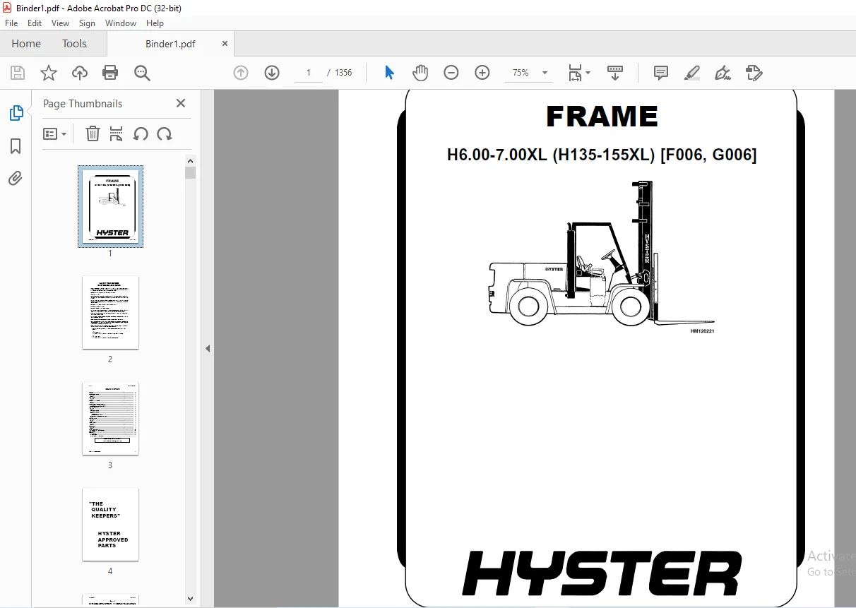
Hyster G006 (H135-155XL) Service Manual – PDF DOWNLOAD
Original price was: $89.95.$33.95Current price is: $33.95.
Hyster G006 (H135-155XL) Service Manual – PDF DOWNLOAD
PART NO. 897104
Description
Hyster G006 (H135-155XL) Service Manual – PDF DOWNLOAD
DESCRIPTION:
Hyster G006 (H135-155XL) Service Manual – PDF DOWNLOAD
PART NO. 897104
SAFETY PRECAUTIONS MAINTENANCE AND REPAIR
• When lifting parts or assemblies, make sure all slings, chains, or cables are correctly
fastened, and that the load being lifted is balanced. Make sure the crane, cables, and
chains have the capacity to support the weight of the load.
• Do not lift heavy parts by hand, use a lifting mechanism.
• Wear safety glasses.
• DISCONNECT THE BATTERY CONNECTOR before doing any maintenance or repair
on electric lift trucks. Disconnect the battery ground cable on internal combustion lift
trucks.
• Always use correct blocks to prevent the unit from rolling or falling. See HOW TO PUT
THE LIFT TRUCK ON BLOCKS in the Operating Manual or the Periodic Maintenance
section.
• Keep the unit clean and the working area clean and orderly.
• Use the correct tools for the job.
• Keep the tools clean and in good condition.
• Always use HYSTER APPROVED parts when making repairs. Replacement parts
must meet or exceed the specifications of the original equipment manufacturer.
• Make sure all nuts, bolts, snap rings, and other fastening devices are removed before
using force to remove parts.
• Always fasten a DO NOT OPERATE tag to the controls of the unit whenmaking repairs,
or if the unit needs repairs.
• Be sure to follow the WARNING and CAUTION notes in the instructions.
• Gasoline, Liquid Petroleum Gas (LPG), Compressed Natural Gas (CNG), and Diesel fuel
are flammable. Be sure to follow the necessary safety precautions when handling these
fuels and when working on these fuel systems.
• Batteries generate flammable gas when they are being charged. Keep fire and sparks
away from the area. Make sure the area is well ventilated.
TABLE OF CONTENTS:
Hyster G006 (H135-155XL) Service Manual – PDF DOWNLOAD
897104-0100SRM0322-(02-2007)-US-EN...................................................... 1 toc................................................................................. 1 Frame........................................................................... 1 Safety Precautions Maintenance and Repair....................................... 2 General......................................................................... 5 Description..................................................................... 5 Counterweight Repair............................................................ 6 Remove...................................................................... 6 Install..................................................................... 6 Hood Repair..................................................................... 7 Remove...................................................................... 7 Install..................................................................... 7 Overhead Guard Repair........................................................... 7 Remove...................................................................... 7 Install..................................................................... 7 Operator Restraint System Repair................................................ 8 Automatic Locking Retractor (ALR)........................................... 8 Emergency Locking Retractor (ELR)........................................... 8 Hydraulic Tank Repair........................................................... 10 Remove...................................................................... 10 Inspect..................................................................... 10 Small Leaks Repair.......................................................... 10 Large Leaks Repair.......................................................... 10 Clean....................................................................... 10 Steam Method............................................................ 11 Chemical Solution Method................................................ 11 Other Methods of Preparation for Repair..................................... 11 Install..................................................................... 11 Fuel Tank Repair................................................................ 12 Remove...................................................................... 12 Repair...................................................................... 12 Install..................................................................... 12 Radiator Repair................................................................. 12 Remove...................................................................... 12 Install..................................................................... 12 Engine Repair................................................................... 13 Remove...................................................................... 13 Install..................................................................... 13 Throttle Pedal Adjustment....................................................... 15 Perkins 1104C-44(RE) Diesel Engine.......................................... 15 Safety Labels................................................................... 16 Cab Repair...................................................................... 18 Cab, Replace................................................................ 18 Window, Replace............................................................. 18 Windshield Wipers and Heater................................................ 18 tables.............................................................................. 1 Table 1. Material Specifications for Cab Windows................................ 20 897106-1300SRM0324-(10-2003)-US-EN...................................................... 23 toc................................................................................. 23 Two-Speed Powershift Transmission............................................... 23 Safety Precautions Maintenance and Repair....................................... 24 General......................................................................... 27 Mechanical Description.......................................................... 27 Torque Converter............................................................ 27 Transmission Pump........................................................... 28 Shaft Assemblies............................................................ 28 Input Shaft................................................................. 29 Forward Clutch Shaft........................................................ 29 Clutch Assemblies........................................................... 29 Countershaft................................................................ 36 Output Shaft................................................................ 36 Hydraulic Operation............................................................. 37 Torque Converter............................................................ 37 Seal Rings.................................................................. 38 Control Valve................................................................... 38 System Pressure Regulator................................................... 41 Clutch Pressure Regulator................................................... 41 Torque Converter Regulator.................................................. 42 Inching Spool............................................................... 42 Direction Spool, Direction Control Lever.................................... 42 Direction Spool, MONOTROL Pedal............................................. 43 Range Spool................................................................. 43 Drain Spool................................................................. 44 Accumulator................................................................. 44 Modulator Spool............................................................. 44 Operation................................................................... 44 Lubrication Circuit............................................................. 45 MONOTROL Pedal.................................................................. 45 Oil Flow Diagrams............................................................... 47 Neutral..................................................................... 47 Forward-Low................................................................. 48 Forward-Low-Inching......................................................... 49 Reverse-Low................................................................. 50 897107-1300SRM0325-(10-2003)-US-EN...................................................... 53 toc................................................................................. 53 Two-Speed Powershift Transmission............................................... 53 Safety Precautions Maintenance and Repair....................................... 54 General......................................................................... 57 Transmission Repair............................................................. 57 Transmission and Torque Converter, Remove................................... 57 Transmission, Disassemble................................................... 59 Reverse-Low Clutch, Disassemble............................................. 62 Reverse-High Clutch, Disassemble............................................ 65 Forward-Low Clutch, Disassemble............................................. 68 Forward-High Clutch, Disassemble............................................ 71 Clean and Inspect........................................................... 73 Forward Low and High Clutches Assembly.......................................... 74 Forward Clutches, Assemble.................................................. 76 Reverse-Low Clutch, Assemble................................................ 82 Reverse Clutches, Assemble.................................................. 84 Transmission, Assemble...................................................... 91 Torque Converter, Install................................................... 98 Control Valve Repair............................................................ 99 Remove...................................................................... 99 Disassemble................................................................. 100 Assemble.................................................................... 101 Install..................................................................... 103 MONOTROL Pedal.................................................................. 103 Remove and Disassemble...................................................... 103 Assemble and Install........................................................ 103 Stall Test...................................................................... 106 Linkage Adjustments............................................................. 107 Linkage for Inching Pedal H6.00-7.00XL (H135-155XL, H135-155XL 2............ 107 Linkage for Inching Pedal S6.00-7.00XL (S135-155XL, S135-155XL 2............ 110 Linkage for Range Lever - Early Model H6.00-7.00XL (H135-155XL) ............ 113 Linkage for Direction Control Lever - Early Model H6.00-7.00XL (............ 113 Linkage for Range Lever - Later Model H6.00-7.00XL (H135-155XL, ............ 115 Linkage for Direction Control Lever - Later Model H6.00-7.00XL (............ 117 Linkage for Range Lever S6.00-7.00XL (S135-155XL, S135-155XL 2 )............ 119 Linkage for Direction Control Lever S6.00-7.00XL (S135-155XL, S1............ 119 Oil Pressure Check.............................................................. 121 System Pressure Check Port.................................................. 121 Torque Converter Check Port................................................. 121 Clutch Pressure Check Port.................................................. 121 Inching Pressure............................................................ 122 Solenoid Check Ports (MONOTROL Control Only)................................ 122 Lubrication Pressure Check Ports............................................ 122 Specifications.................................................................. 123 Troubleshooting................................................................. 123 Correct System Pressure: 1300 ±124 kPa ( 189 ±18 psi)....................... 126 Correct Clutch Pressure: 924 ±69 kPa ( 134 ±10 psi)......................... 127 Correct Solenoid Pressure (MONOTROL Only): 965 ±138 kPa ( 140 ±2............ 128 Torque Converter Pressure: 834 ±69 kPa ( 121 ±10 psi)....................... 128 Lubrication Pressure: 83 ±21 kPa ( 12 ±3 psi)............................... 128 tables.............................................................................. 53 Table 1. Stall Speed Specifications............................................. 106 897108-1600SRM0326-(03-2007)-US-EN...................................................... 131 toc................................................................................. 131 Steering Axle................................................................... 131 Safety Precautions Maintenance and Repair....................................... 132 General......................................................................... 135 Description..................................................................... 135 Steering Axle Assembly Repair................................................... 140 Steering Axle H3.50-5.00XL (H70-110XL) (G005), S3.50-5.50XL (S70............ 140 Remove.................................................................. 140 Install................................................................. 140 Steering Axle H6.00-7.00XL (H135-155XL, H135-155XL 2 ) (F006, G0............ 141 Remove.................................................................. 141 Install................................................................. 141 Wheels and Hubs Repair (All Units).............................................. 142 Remove and Disassemble...................................................... 142 Clean....................................................................... 142 Inspect..................................................................... 142 Assemble and Install........................................................ 142 Spindles and Bearings Repair (All Units)........................................ 144 Remove...................................................................... 144 Clean....................................................................... 144 Assemble and Install........................................................ 145 Tie Rods Repair (All Units)..................................................... 146 Remove...................................................................... 146 Clean....................................................................... 146 Install..................................................................... 146 Steering Cylinder Repair........................................................ 149 Remove and Disassemble...................................................... 149 Clean and Inspect........................................................... 149 Assemble and Install........................................................ 149 Troubleshooting................................................................. 150 897109-1800SRM0327-(09-2003)-US-EN...................................................... 155 toc................................................................................. 155 Brake System.................................................................... 155 Safety Precautions Maintenance and Repair....................................... 156 General......................................................................... 159 Description..................................................................... 159 Operation....................................................................... 160 Brake Booster and Master Cylinder........................................... 160 Brake Booster........................................................... 160 Master Cylinder......................................................... 161 Service Brake Assembly...................................................... 162 Parking Brake............................................................... 163 Brake Shoe Assemblies Repair.................................................... 164 Remove and Disassemble...................................................... 164 Clean and Inspect........................................................... 165 Cleaning Procedures..................................................... 165 Inspect................................................................. 165 Assemble and Install........................................................ 166 Master Cylinder Repair.......................................................... 167 Remove...................................................................... 167 Disassemble................................................................. 167 Assemble.................................................................... 169 Install..................................................................... 169 Brake Booster Repair............................................................ 169 Remove...................................................................... 169 Disassemble................................................................. 169 Clean and Inspect........................................................... 171 Assemble.................................................................... 171 Install..................................................................... 171 Brake System Air Removal........................................................ 171 Brake Pedal Adjustment.......................................................... 172 Brake Shoes Adjustment.......................................................... 173 Parking Brake Adjustment........................................................ 173 Parking Brake Switch Adjustment................................................. 173 Brake Booster Relief Valve Check................................................ 173 Troubleshooting................................................................. 174 897110-1900SRM0328-(09-2003)-US-EN...................................................... 179 toc................................................................................. 179 Hydraulic System................................................................ 179 Safety Precautions Maintenance and Repair....................................... 180 General......................................................................... 183 Description and Operation....................................................... 183 Hydraulic Pumps............................................................. 185 Main Control Valve.......................................................... 185 Control Valve Lever......................................................... 186 Steering Control Unit....................................................... 186 Brake Valve................................................................. 186 Oil Clutch, H6.00-7.00XL (H135-155XL) (F006)................................ 187 Troubleshooting................................................................. 187 Lift, Lower, and Tilt Circuit............................................... 188 Steering, Brake, and Oil Clutch System...................................... 189 897111-4000SRM0329-(10-2003)-US-EN...................................................... 193 toc................................................................................. 193 Masts........................................................................... 193 Safety Precautions Maintenance and Repair....................................... 194 General......................................................................... 197 Description and Operation....................................................... 197 General..................................................................... 197 Safety Procedures When Working Near Mast.................................... 198 Two-Stage Mast.............................................................. 198 Three-Stage Mast............................................................ 200 Carriage Repair................................................................. 202 Remove...................................................................... 202 Sideshift Carriage, Disassemble............................................. 202 Sideshift Carriage, Assemble................................................ 203 Install..................................................................... 203 Two-Stage Mast Repair........................................................... 205 Remove...................................................................... 205 Disassemble................................................................. 206 Clean and Inspect........................................................... 207 Assemble.................................................................... 208 Install..................................................................... 208 Three-Stage Mast Repair......................................................... 210 Remove...................................................................... 210 Disassemble................................................................. 210 Clean and Inspect........................................................... 210 Assemble.................................................................... 210 Install..................................................................... 212 Mast Operation Check............................................................ 212 Lift and Tilt System Leaks Check................................................ 213 Lift System................................................................. 213 Tilt System................................................................. 213 Tilt Cylinder Stroke and Backward Tilt Angle Adjustment......................... 214 Lift Chain Adjustments.......................................................... 214 Mast Adjustments................................................................ 217 Carriage Adjustment............................................................. 217 Troubleshooting................................................................. 219 tables.............................................................................. 193 Table 1. Mast Parts Weight...................................................... 206 Table 2. Hook-Type Carriage Chain Adjustment.................................... 215 Table 3. Pin-Type Carriage Chain Adjustment..................................... 215 897113-8000SRM0331-(09-2003)-US-EN...................................................... 223 toc................................................................................. 223 Capacities and Specifications................................................... 223 Safety Precautions Maintenance and Repair....................................... 224 Lift Truck Weights.............................................................. 227 Capacities...................................................................... 227 Tire Sizes...................................................................... 228 Tire Pressure................................................................... 228 Electrical System............................................................... 228 Wheel Nut Torque................................................................ 228 Engine Specifications........................................................... 229 Hydraulic System................................................................ 229 Mast Speeds..................................................................... 230 Transmission Oil Pressures...................................................... 230 Torque Specifications........................................................... 231 Engine - GM 4.3L V-6........................................................ 231 Engine - Perkins 4.2482..................................................... 231 Engine - Perkins 1004.4..................................................... 231 Clutch...................................................................... 231 Manual Transmission......................................................... 232 Powershift Transmission..................................................... 232 Speed Reducer............................................................... 232 Drive Axle.................................................................. 232 Steering System............................................................. 232 Brake System................................................................ 232 Hydraulic System............................................................ 233 Tilt Cylinder............................................................... 233 Mast........................................................................ 233 897123-8000SRM0341-(06-2007)-US-EN...................................................... 237 toc................................................................................. 237 Periodic Maintenance............................................................ 237 Safety Precautions Maintenance and Repair....................................... 238 General......................................................................... 243 Serial Number Data.......................................................... 243 How to Move Disabled Truck.................................................. 243 How to Tow Lift Truck................................................... 243 How to Put Lift Truck on Blocks............................................. 244 How to Raise Drive Tires................................................ 244 How to Raise Steering Tires............................................. 244 Maintenance Schedule............................................................ 245 Maintenance Procedures Every 8 Hours or Daily................................... 258 How to Make Checks With Engine Stopped...................................... 258 Hydraulic System Oil.................................................... 258 Engine Oil.............................................................. 260 Drive Belts............................................................. 260 Intake Manifold Rubber Cap.............................................. 261 Cooling System.......................................................... 261 Air Filter.............................................................. 261 Fuel System............................................................. 262 Primary Fuel Filter, Diesel Engine...................................... 262 Battery................................................................. 262 Tires and Wheels........................................................ 262 Forks................................................................... 263 Adjust.............................................................. 263 Remove and Install.................................................. 265 Forks, Mast, and Lift Chains, Inspect................................... 266 Operator Restraint System............................................... 267 Automatic Locking Retractor (ALR)................................... 267 Emergency Locking Retractor (ELR)................................... 267 Safety Labels........................................................... 268 How to Make Checks With Engine Running...................................... 269 Gauges, Lights, Horn, and Fuses......................................... 269 Oil Level, Powershift Transmission...................................... 270 Oil Level, Oil Clutch System, H3.50-5.00XL (H70-110XL).................. 271 Control Levers and Pedals............................................... 271 Lift System Operation................................................... 271 Inching/Brake Pedal..................................................... 271 Service Brakes.......................................................... 271 Parking Brake........................................................... 272 Steering System......................................................... 272 Maintenance Procedures Every 250 Hours or 6 Weeks............................... 272 Engine Oil and Filter, GM V-6 Engine........................................ 272 Lift Chains, Lubrication.................................................... 272 Drive Shafts................................................................ 272 Mast Lubrication............................................................ 273 Crankcase Breather, GM V-6.................................................. 274 Air Filter, GM V-6 EPA Compliant Engine .................................... 274 Maintenance Procedures Every 350 Hours or 2 Months.............................. 275 Engine Oil and Filter, Perkins 4.2482 Diesel Engine......................... 275 Drive Belts................................................................. 275 Perkins Diesel Engine................................................... 275 GM V-6 Engine (Early Models)............................................ 275 GM V-6 Engine (Late Models)............................................. 276 Brake Fluid................................................................. 278 Lift Chains Wear Check...................................................... 278 Forks Wear and Damage Check................................................. 278 Steering Axle Lubrication................................................... 278 Fuel System, Checks and Adjustments......................................... 279 Diesel Fuel System...................................................... 279 LPG Carburetor (Early Models)........................................... 279 Gasoline Carburetor (Early Models)...................................... 280 Fuel Injection (Late Models)............................................ 280 Crankcase Breather, Perkins 4.2482 Diesel Engine............................ 280 Hydraulic Tank Breather..................................................... 280 Cooling System, Clean Debris from Radiator Core............................. 280 Maintenance Procedures Every 500 Hours or 3 Months.............................. 281 Engine Oil and Filter, Perkins Diesel Engine................................ 281 Crankcase Breather, Perkins Diesel Engine................................... 281 PCV Valve, GM V-6........................................................... 281 Maintenance Procedures Every 1000 Hours or 6 Months............................. 281 Manifold Heat Valve, GM V-6 (Early Models).................................. 281 Ignition System, GM V-6..................................................... 281 Valve Clearance Adjustment.................................................. 281 Fuel Filter, Replace (Diesel Engine)........................................ 282 Fuel System Air Removal (Perkins 1004-4 Diesel Engine)...................... 282 Fuel Injection Pump With Vent Tube...................................... 282 Fuel Injection Pump With Vent Screw..................................... 283 Fuel System Air Removal (Perkins 4.2482 Diesel Engine)...................... 285 Oil Level Check in Transmission............................................. 285 Manual Transmission, H3.50-5.00XL (H70-110XL)........................... 285 Speed Reducer for Powershift Transmission, H3.50-5.00XL (H70-110........ 285 Manual Transmission, H6.00-7.00XL (H135-155XL).......................... 285 Differential and Drive Axle for Powershift Transmission, H6.00-7........ 285 Differential, Speed Reducer, and Drive Axle for Manual Transmiss........ 286 Control Levers and Pedals, Lubricate........................................ 286 Crankcase Breather, Replace................................................. 286 Cooling System, GM V-6 EPA Compliant Engine................................. 286 Spark Plug Replacement...................................................... 286 Remove.................................................................. 286 Install................................................................. 287 LPG Fuel Filter GM V-6 EPA Compliant Engine, Replace........................ 287 Inspect Engine Electrical System, Connectors, and FCVS Connectio............ 288 Maintenance Procedures Every 2000 Hours or Yearly............................... 288 Hydraulic System............................................................ 288 Hydraulic Oil and Filter, H3.50-5.00XL (H70-110XL), Replace............. 288 Hydraulic Oil and Filter, H6.00-7.00XL (H135-155XL, H135-155XL 2........ 289 Oil Change and Oil Filter Replacement, Powershift Transmission, ............ 289 Oil Change, Manual Transmission, H3.50-5.00XL (H70-110XL)................... 289 Oil Change, Manual Transmission, H6.00-7.00XL (H135-155XL).................. 289 Oil Change, Speed Reducer, Powershift Transmission, H3.50-5.00XL............ 289 Oil and Filter Change, Oil Clutch System, H3.50-5.00XL (H70-110X............ 290 Oil Change, Differential and Drive Axle, Powershift Transmission............ 290 Oil Change, Differential, Speed Reducer, and Drive Axle, Manual ............ 290 Cooling System.............................................................. 290 PCV Valve, GM V-6........................................................... 290 Service Brakes.............................................................. 291 LPG Filter, Replace......................................................... 291 Gasoline Fuel Filter, Replace............................................... 292 Hood Latch Check, H3.50-5.00XL (H70-110XL).................................. 292 Air Filter Element, GM V-6 EPA Compliant Engine............................. 292 Oxygen Sensor GM V-6 EPA Compliant Engine................................... 292 Inspect Low Pressure Regulator (LPR) for Oil Buildup and Leaks.............. 293 Check Throttle Shaft for Sticking........................................... 294 Inspect Exhaust Manifold and Piping for Leaks............................... 294 Test LPG/GAS Regulator Pressure............................................. 294 Safety Procedures When Working Near Mast........................................ 294 Lift Chain Adjustments.......................................................... 296 Fuel Injectors Repair........................................................... 298 Lift and Tilt System Leak Check................................................. 299 Lift Cylinders, Leak Check.................................................. 299 Tilt Cylinders, Leak Check.................................................. 299 Welding Repairs................................................................. 300 Overhead Guard Changes.......................................................... 300 Wheel and Tire Replacement...................................................... 301 Remove Wheels From Lift Truck............................................... 301 Remove Wheels From Tire..................................................... 301 Remove Tire From Two-Piece Wheel........................................ 303 Remove Tire From Three- and Four-Piece Wheels........................... 305 Install Wheel in Tire....................................................... 306 Install Three- or Four-Piece Wheel in Tire.............................. 307 Install Two-Piece Wheel in Tire......................................... 308 Add Air to Pneumatic Tires.................................................. 309 Wheels, Install............................................................. 309 Solid Rubber Tires Repair....................................................... 310 Wheel, Tire Remove.......................................................... 310 Wheel, Tire Install......................................................... 312 SIT Tire, Change for H3.50-5.00XL (G005), and H6.00-7.00XL (F006............ 314 Remove SIT Solid Tire From Wheel........................................ 314 Install SIT Solid Tire on Wheel......................................... 315 Adhesives and Sealants.......................................................... 316 Hydraulic Oil, Lubricant, and Coolant Specifications............................ 317 tables.............................................................................. 237 Table 1. Maintenance Schedule................................................... 247 Table 2. Hook-Type Carriage Chain Adjustment.................................... 297 Table 3. Pin-Type Carriage Chain Adjustment..................................... 297 897501-8000SRM0519-(06-2007)-US-EN...................................................... 321 toc................................................................................. 321 Diagrams........................................................................ 321 Safety Precautions Maintenance and Repair....................................... 322 897800-0600SRM0590-(08-2005)-US-EN...................................................... 409 toc................................................................................. 409 GM Engines...................................................................... 409 Safety Precautions Maintenance and Repair....................................... 410 General......................................................................... 413 Description..................................................................... 413 Engine Removal and Installation................................................. 414 Cylinder Head Repair............................................................ 414 Remove and Disassemble...................................................... 414 Clean and Inspect........................................................... 414 Valve Guides and Seats, Repairs............................................. 415 Valves, Repair.............................................................. 415 Valve Seats, Repair......................................................... 416 Valve Springs............................................................... 416 Rocker Arm Studs (Early Models)............................................. 418 Rocker Arm Studs (Late Models).............................................. 418 Assemble and Install........................................................ 419 Cylinder Block Cleaning and Inspection.......................................... 422 Piston Bore Preparation......................................................... 422 Engine Mounts Installation...................................................... 423 Lubrication System Repair....................................................... 423 Oil Pump, Remove and Disassemble............................................ 423 Clean and Inspect........................................................... 423 Oil Pump, Assemble and Install.............................................. 424 Oil Sump, Install........................................................... 424 Timing Cover, Timing Sprockets, Camshaft, and Valve Lifters..................... 425 Timing Cover................................................................ 425 Remove.................................................................. 425 Install................................................................. 427 Timing Sprockets............................................................ 427 Remove.................................................................. 427 Install................................................................. 427 Camshaft.................................................................... 428 Remove.................................................................. 428 Inspect................................................................. 428 Install................................................................. 428 Balance Shaft............................................................... 429 Remove.................................................................. 429 Install................................................................. 430 Hydraulic Valve Lifters..................................................... 430 Remove.................................................................. 430 Disassemble............................................................. 431 Clean and Inspect....................................................... 431 Assemble................................................................ 431 Install................................................................. 432 Crankshaft Repair............................................................... 433 Remove...................................................................... 433 Inspect and Repair.......................................................... 433 How to Check Clearance Between Main Bearings and Their Journals............. 434 Install..................................................................... 435 Piston and Connecting Rod Assemblies Repair..................................... 436 Connecting Rod Bearings, Replace............................................ 436 Piston and Connecting Rod Assemblies, Remove................................ 437 Disassemble................................................................. 437 Piston, Clean and Inspect................................................... 438 Cylinder Bores, Inspect and Repair.......................................... 438 Piston Rings................................................................ 439 Assemble.................................................................... 440 Piston and Connecting Rod Assemblies, Install............................... 440 Flywheel and Flywheel Housing Repair............................................ 441 Flywheel, Repair............................................................ 441 Flywheel, Install........................................................... 441 H3.50-5.00XL (H70-110XL), S3.50-5.50XL (S70-120XL), S6.00-7.00XL........ 441 H6.00-7.00XL (H135-155XL)............................................... 441 Flywheel Housing H3.50-5.00XL (H70-110XL), H3.50-5.50XM (H70-120............ 441 Engine Adapter H6.00-7.00XL (H135-155XL).................................... 441 Coolant Pump Repair............................................................. 442 Thermostat Replacement.......................................................... 442 Fan Mount Repair (Early Models)................................................. 442 Fan Mount Assembly Repair (Late Models)......................................... 442 Drive Belt Installation......................................................... 444 Valve Clearance Adjustment (Early Models)....................................... 445 Valve Clearance Adjustment (New Models)......................................... 446 Compression Check............................................................... 446 Engine Specifications........................................................... 447 Engine Data................................................................. 447 Cylinder Head............................................................... 447 Hydraulic Valve Lifter...................................................... 448 Camshaft.................................................................... 448 Pistons..................................................................... 448 Crankshaft.................................................................. 449 Connecting Rods............................................................. 449 Balance Shaft............................................................... 450 Cooling System.............................................................. 450 Lubrication System.......................................................... 450 Torque Specifications........................................................... 450 Troubleshooting................................................................. 451 tables.............................................................................. 409 Table 1. Piston Rings Arrangement on Piston..................................... 440 897934-0700SRM0626-(11-2001)-US-EN...................................................... 457 toc................................................................................. 457 Cooling System.................................................................. 457 Safety Precautions Maintenance and Repair....................................... 458 General......................................................................... 461 Description..................................................................... 462 Radiator.................................................................... 462 Radiator Cap................................................................ 462 Thermostat.................................................................. 462 Water Pump.................................................................. 463 Fan and Fan Shroud.......................................................... 463 Cooling System Checks........................................................... 463 Radiator.................................................................... 463 Thermostat.................................................................. 463 Water Pump.................................................................. 464 Exhaust Leaks............................................................... 464 Fan and Fan Shroud.......................................................... 464 Radiator Cleaning............................................................... 464 Drain....................................................................... 464 Clean....................................................................... 464 Fill........................................................................ 465 Troubleshooting................................................................. 466 899783-2000SRM0090-(10-2003)-US-EN...................................................... 469 toc................................................................................. 469 Main Control Valve.............................................................. 469 Safety Precautions Maintenance and Repair....................................... 470 General......................................................................... 473 Description..................................................................... 473 Operation....................................................................... 476 Lift Spool.................................................................. 476 Tilt Spool.................................................................. 477 Tilt Backward........................................................... 477 Tilt Forward............................................................ 478 Single-Stage Relief Valve................................................... 480 Two-Stage Relief Valve...................................................... 481 Main Control Valve Repair....................................................... 482 Remove and Disassemble...................................................... 482 Clean and Inspect........................................................... 482 Assemble.................................................................... 482 Install..................................................................... 483 Single-Stage Relief Valve Adjustment............................................ 483 Two-Stage Relief Valve.......................................................... 484 Auxiliary Control Valve Relief Valve Adjustment (H60-110E Only)................. 484 Troubleshooting................................................................. 485 tables.............................................................................. 469 Table 1. Relief Pressures (Oil temperature at 55 to 66 C ( 131 t................ 483 899784-2200SRM0002-(12-2004)-US-EN...................................................... 489 toc................................................................................. 489 Alternator with Regulator....................................................... 489 Safety Precautions Maintenance and Repair....................................... 490 General......................................................................... 493 Description..................................................................... 493 Alternator Repair............................................................... 495 Alternator Type A........................................................... 495 Remove and Disassemble.................................................. 495 Clean................................................................... 496 Assemble................................................................ 497 Install................................................................. 497 Alternator Type B........................................................... 500 Remove and Disassemble.................................................. 500 Clean................................................................... 500 Assemble................................................................ 501 Install................................................................. 502 General Check and Adjustment.................................................... 503 Low Output Check (Type A or Type B)............................................. 503 High Output Check (Type A or Type B)............................................ 505 Brushes Circuit Check........................................................... 506 Delco Alternators........................................................... 506 Motorola Alternators........................................................ 507 Diodes Check.................................................................... 508 Diode Bridge Check.............................................................. 508 Delco and Leece-Neville Alternators......................................... 508 Motorola Alternators........................................................ 508 Rotor Field Winding Check....................................................... 509 Stator Windings Check........................................................... 510 Voltage Regulator Check......................................................... 510 Troubleshooting................................................................. 510 910072-1400SRM0046-(07-2007)-US-EN...................................................... 515 toc................................................................................. 515 Differential.................................................................... 515 Safety Precautions Maintenance and Repair....................................... 516 General......................................................................... 519 Description..................................................................... 519 Differential Repair............................................................. 520 Remove...................................................................... 520 Differential Carrier From Axle Housing, Remove.......................... 520 Differential and Ring Gear From Differential Carrier, Remove............ 522 Drive Pinion and Pinion Carrier From Differential Carrier, Remov........ 524 Disassemble................................................................. 525 Differential and Ring Gear Assembly, Disassemble........................ 525 Drive Pinion and Pinion Carrier, Disassemble............................ 527 Clean and Inspect........................................................... 530 Assemble.................................................................... 531 Pinion, Bearings, and Pinion Carrier, Assemble.......................... 531 Pinion Bearings, Adjust Preload......................................... 531 Press Method........................................................ 531 Yoke or Flange Method............................................... 532 Triple-Lip Seal, Install................................................ 533 Pinion Carrier Shim Set, Adjust Thickness (Depth of Pinion)............. 534 Differential and Ring Gear, Assemble.................................... 536 Differential Gears Rotating Torque, Check............................... 538 Differential and Ring Gear Assembly, Install............................ 539 Differential Bearings, Preload Adjust................................... 541 Ring Gear, Runout Check................................................. 542 Ring Gear Backlash, Adjust.............................................. 542 Gear Set, Tooth Contact Pattern Check................................... 544 Thrust Screw, Install and Adjust........................................ 547 Install..................................................................... 547 Differential Assembly Into Axle Housing, Install........................ 547 Specifications.................................................................. 549 Troubleshooting................................................................. 554 tables.............................................................................. 515 Table 1. Ring Gear Backlash Adjustment Specifications........................... 544 Table 2. Ring and Pinion Tooth Contact Adjustment............................... 545 Table 3. General Specifications................................................. 549 Table 4. Rivet Installation Pressure............................................ 549 Table 5. Pinion Adjustment...................................................... 550 Table 6. Pinion Preload Pressure................................................ 550 Table 7. Torque Specifications.................................................. 551 Table 8. Torque Specifications for Metric Hardware.............................. 552 Table 9. Torque Specifications for Metric (Fine) Hardware....................... 553 910073-1400SRM0049-(09-2003)-US-EN...................................................... 557 toc................................................................................. 557 Drive Axle...................................................................... 557 Safety Precautions Maintenance and Repair....................................... 558 General......................................................................... 561 Description..................................................................... 561 Drive Axle Repair............................................................... 562 Disassemble (Type 1 Shown).................................................. 562 Clean....................................................................... 565 Inspect..................................................................... 565 Assemble (Type 1 Shown)..................................................... 566 Torque Specifications........................................................... 569 Troubleshooting................................................................. 570 910076-1600SRM0054-(10-2003)-US-EN...................................................... 573 toc................................................................................. 573 Steering Control Unit........................................................... 573 Safety Precautions Maintenance and Repair....................................... 574 General......................................................................... 577 Description..................................................................... 577 Operation....................................................................... 577 Steering Wheel and Column Assembly Repair....................................... 579 Steering Column Assembly Repair................................................. 579 Type A Steering Column Assembly............................................. 579 Remove and Disassemble.................................................. 579 Assemble and Install.................................................... 581 Type B Steering Column Assembly............................................. 583 Remove and Disassemble.................................................. 583 Assemble and Install.................................................... 583 Steering Control Unit................................................... 586 Disassemble......................................................... 586 Clean............................................................... 589 Assemble............................................................ 590 System Air Removal.............................................................. 595 Troubleshooting................................................................. 595 910091-1900SRM0097-(07-2006)-US-EN...................................................... 599 toc................................................................................. 599 Hydraulic Gear Pumps............................................................ 599 Safety Precautions Maintenance and Repair....................................... 600 Description..................................................................... 603 Operation....................................................................... 604 Flow Control Valve.......................................................... 604 Relief Valve................................................................ 605 Hydraulic Gear Pump Repair...................................................... 605 Remove...................................................................... 605 Disassemble................................................................. 606 Clean....................................................................... 606 Inspect..................................................................... 607 Assemble.................................................................... 610 Install..................................................................... 612 Pump Output Check............................................................... 612 Method No. 1................................................................ 612 Method No. 2................................................................ 613 Hydraulic System Air Check...................................................... 614 Troubleshooting................................................................. 615 910102-2100SRM0103-(03-2007)-US-EN...................................................... 621 toc................................................................................. 621 Tilt Cylinders.................................................................. 621 Safety Precautions Maintenance and Repair....................................... 622 General......................................................................... 625 Description..................................................................... 625 Tilt Cylinder Repair............................................................ 625 Remove...................................................................... 625 Disassemble................................................................. 625 Clean....................................................................... 625 Assemble.................................................................... 625 Tilt Cylinders With O-Ring or Single-Lip Seals.......................... 625 Tilt Cylinders for XM and XMS Models.................................... 627 Tilt Cylinders for XL, XLS, and XL 3 Models............................. 628 Tilt Cylinders for H700-800A and Early Model H700-920B.................. 630 Install..................................................................... 631 Tilt Cylinders Using Chevron Packing.................................... 631 Install............................................................. 632 Tilt Cylinder Leak Check........................................................ 634 Tilt Cylinder Stroke and Mast Tilt Angle Adjustment............................. 636 Torque Specifications........................................................... 636 Piston Rod Nut.............................................................. 636 Retainer.................................................................... 637 Troubleshooting................................................................. 639 tables.............................................................................. 621 Table 1. Movement Rates (Maximum) for Tilt Cylinders............................ 635 910107-2200SRM0106-(12-2004)-US-EN...................................................... 643 toc................................................................................. 643 Starter......................................................................... 643 Safety Precautions Maintenance and Repair....................................... 644 General......................................................................... 647 Description and Operation....................................................... 647 Starter Repair.................................................................. 649 Remove...................................................................... 649 Disassemble................................................................. 649 Clean....................................................................... 650 Assemble.................................................................... 650 Install..................................................................... 651 General Checks and Adjustments.................................................. 651 Troubleshooting................................................................. 654 910110-2200SRM0143-(02-2007)-US-EN...................................................... 659 toc................................................................................. 659 Instrument Panel Indicators and Senders......................................... 659 Safety Precautions Maintenance and Repair....................................... 660 General......................................................................... 663 Description..................................................................... 664 Steering Column Gauges, Meters, and Indicators.............................. 664 LED Display Panel........................................................... 664 Battery Discharge Indicators............................................ 664 Brush Wear Indicators................................................... 670 Motor Temperature Indicators............................................ 670 LX Series Display Panel..................................................... 672 Hourmeter Functions..................................................... 673 Battery Indicator Function.............................................. 673 Status Code Function.................................................... 673 ZX Series Display Panels.................................................... 675 Display Panel........................................................... 675 Basic Display Panels.................................................... 675 Performance Display..................................................... 677 Brush Wear Indicators................................................... 681 Adjustments - General........................................................... 681 Replacement - General Information............................................... 681 Meter Replacement............................................................... 682 Sender Replacement.............................................................. 683 Fuel Level Sender........................................................... 683 Pressure and Temperature Sender............................................. 683 Seat Sensor, Operator Presence System (OPS)................................. 684 Remove.................................................................. 684 Install................................................................. 684 Operator Presence System Module Replacement................................. 684 Remove.................................................................. 685 Install................................................................. 686 ITW Display Panel Replacement................................................... 687 Remove...................................................................... 687 Column Mount Display Panel (EV-100/200ZX Motor Controllers) Repl................ 687 Remove...................................................................... 687 Display Panel Assembly, Replace............................................. 687 Indicator LEDs.............................................................. 688 Battery Indicators.......................................................... 688 Digital Display (Performance Display Panel Only)............................ 688 Status Code or Performance Level Switches and Indicator LEDs (Pe............ 689 Basic Display Panel, Replace Parts.......................................... 689 Performance Display Panel, Replace Parts.................................... 691 Dash Mount Display Panel (EV100/200ZX Motor Controllers) Replace................ 691 Remove and Replace.......................................................... 691 Specifications.................................................................. 692 Meter Specifications........................................................ 692 Sender Specifications....................................................... 692 Troubleshooting................................................................. 693 Meter....................................................................... 693 Troubleshooting for Operator Presence System.................................... 694 tables.............................................................................. 659 Table 1. Troubleshooting Procedure for Operator Presence Module................. 694 910119-4000SRM0135-(10-2003)-US-EN...................................................... 699 toc................................................................................. 699 Lift Cylinders.................................................................. 699 Safety Precautions Maintenance and Repair....................................... 700 Safety Procedures When Working Near Mast........................................ 703 General......................................................................... 707 Description..................................................................... 707 Lowering Control Valve...................................................... 707 Cylinders (General)......................................................... 710 Cylinders (H520-620B, H700-800A)............................................ 710 Retainer, Install....................................................... 710 Cylinders (H360-460B)....................................................... 712 Cylinders (Two-Speed)....................................................... 714 Lift Cylinder Repair............................................................ 716 Lift Cylinder Removal Without Removing Mast................................. 716 Standard Masts With Main Lift Cylinder Fastened to Crossmember o........ 716 Standard and Full Free-Lift Masts With Lift Cylinder Fastened to........ 716 Masts That Have Two Cylinders, Main Lift Cylinder and Free-Lift ........ 716 Disassemble................................................................. 718 Assemble.................................................................... 718 Lift Cylinder Installation in Mast.......................................... 720 Standard Masts With Main Lift Cylinder Fastened to Crossmember o........ 720 Standard and Full Free-Lift Masts With Lift Cylinder Fastened to........ 720 Chevron-Style Packing....................................................... 720 Chevron-Style Packing Installation on Piston............................ 721 Chevron-Style Packing Installation in Packing Gland..................... 723 Lift Cylinders for VISTA® Masts................................................. 724 Description................................................................. 724 Lowering Control Valve.................................................. 724 Remove...................................................................... 726 Disassemble................................................................. 727 Assemble.................................................................... 728 Install..................................................................... 729 Main Lift Cylinders..................................................... 729 Free-Lift Cylinder...................................................... 729 Lift System Leak Check.......................................................... 730 Specifications.................................................................. 731 Troubleshooting................................................................. 732 tables.............................................................................. 699 Table 1. Lift Trucks with Two-Speed Lift Cylinders.............................. 715 Table 2. Cylinder Retainer Torque Specifications and Weight Guid................ 731 910442-8000SRM0231-(12-2004)-US-EN...................................................... 735 toc................................................................................. 735 Metric and Inch (SAE) Fasteners................................................. 735 Safety Precautions Maintenance and Repair....................................... 736 General......................................................................... 739 Threaded Fasteners.......................................................... 739 Nomenclature, Threads....................................................... 739 Strength Identification..................................................... 740 Cotter (Split) Pins......................................................... 740 Fastener Torque Tables...................................................... 745 Conversion Table............................................................ 747 tables.............................................................................. 735 Table 1. Bolts and Screws....................................................... 741 Table 2. Studs and Nuts......................................................... 742 Table 3. Torque Nuts............................................................ 743 Table 4. Torque Nuts With Nylon Insert.......................................... 744 Table 5. Torque Values for Metric Fasteners*.................................... 745 Table 6. Torque Values for Inch Fasteners*...................................... 746 Table 7. Conversion Table for Metric and English Units.......................... 747 Table 8. Cotter Pin Dimensional Data............................................ 748 Table 9. Cotter Pin Dimensional Data............................................ 749 Table 10. Cotter Pin Dimensional Data........................................... 750 Table 11. Cotter Pin Dimensional Data........................................... 752 1552002-0600SRM1070-(06-2007)-US-EN..................................................... 757 toc................................................................................. 757 Perkins Diesel Engines.......................................................... 757 Safety Precautions Maintenance and Repair....................................... 758 General......................................................................... 765 General Safety Rules........................................................ 765 Description..................................................................... 766 Engine Serial Number Codes.................................................. 768 Engine Data................................................................. 768 Engine Removal and Installation................................................. 769 Cylinder Head Assembly Repair................................................... 770 Engine Breather............................................................. 770 Remove.................................................................. 770 Install................................................................. 770 Valve Cover................................................................. 771 Remove.................................................................. 771 Install................................................................. 771 Rocker Arm Assembly......................................................... 772 Remove.................................................................. 772 Disassemble............................................................. 772 Inspect................................................................. 772 Assemble................................................................ 773 Install................................................................. 773 Valve Clearance Adjustments................................................. 774 Valve Springs............................................................... 774 Cylinder Head Assembly...................................................... 776 Remove.................................................................. 776 Inspect................................................................. 777 Install................................................................. 777 Valves and Valve Springs.................................................... 779 Remove.................................................................. 779 Inspect................................................................. 779 Install................................................................. 780 Valve Guides................................................................ 780 Inspect................................................................. 780 Remove.................................................................. 781 Install................................................................. 781 Valve Seats................................................................. 782 Inspect................................................................. 782 Repair.................................................................. 782 New Valve Seats, Install................................................ 783 Piston and Connecting Rod Assemblies Repair..................................... 784 General..................................................................... 784 Rod Bearings................................................................ 784 Remove.................................................................. 784 Install................................................................. 785 Piston and Connecting Rod Assembly.......................................... 786 Service Note............................................................ 786 Remove.................................................................. 786 Disassemble............................................................. 786 Inspect................................................................. 786 How to Select Correct Replacements...................................... 788 Assemble................................................................ 788 Install................................................................. 789 Piston Cooling Jets......................................................... 791 Remove.................................................................. 791 Install................................................................. 791 Crankshaft Assembly Repair...................................................... 792 General..................................................................... 792 Crankshaft Pulley........................................................... 792 Remove.................................................................. 792 Inspect................................................................. 792 Install................................................................. 792 Rear Oil Seal............................................................... 793 Remove.................................................................. 793 Install................................................................. 793 Crankshaft Flange Wear Sleeve............................................... 795 Remove.................................................................. 795 Install................................................................. 795 Main Bearings............................................................... 796 Remove.................................................................. 796 Inspect................................................................. 796 Install................................................................. 796 Thrust Washers.............................................................. 797 Crankshaft Axle Movement, Check......................................... 797 Remove.................................................................. 798 Install................................................................. 798 Crankshaft.................................................................. 799 Remove.................................................................. 799 Inspect................................................................. 799 Install................................................................. 800 Crankshaft Timing Ring...................................................... 801 Remove.................................................................. 801 Install................................................................. 802 Flywheel.................................................................... 802 Remove.................................................................. 802 Ring Gear, Replace...................................................... 802 Install................................................................. 802 Flywheel Housing............................................................ 803 Remove.................................................................. 803 Install................................................................. 803 Timing Case and Timing Gears Repair............................................. 804 General..................................................................... 804 Timing Case Cover........................................................... 804 Remove.................................................................. 804 Install................................................................. 804 Front Oil Seal.............................................................. 805 Remove, With Timing Case Installed...................................... 805 Install, With Timing Case Installed..................................... 806 Remove, With Timing Case Removed........................................ 807 Install, With Timing Case Removed....................................... 807 Crankshaft Pulley Wear Sleeve, Install...................................... 807 Fuel Pump Gear.............................................................. 808 Remove.................................................................. 808 Install................................................................. 809 Idler Gear and Hub.......................................................... 810 Remove.................................................................. 810 Disassemble............................................................. 811 Standard Idler Gear and Hub Assembly................................ 811 Heavy Duty Idler Gear and Hub Assembly.............................. 811 Assemble................................................................ 812 Standard Idler Gear and Hub Assembly................................ 812 Heavy Duty Idler Gear and Hub Assembly.............................. 812 Install................................................................. 813 Camshaft Gear............................................................... 813 Remove.................................................................. 813 Install................................................................. 814 Crankshaft Gear............................................................. 814 Remove.................................................................. 814 Install................................................................. 814 Timing Case................................................................. 815 Remove.................................................................. 815 Install................................................................. 816 Power Take-Off (PTO) Adaptor................................................ 817 Remove.................................................................. 817 Disassemble............................................................. 817 Assemble................................................................ 818 Install................................................................. 818 Camshaft and Tappets........................................................ 818 Remove.................................................................. 818 Install................................................................. 818 Cylinder Block Assembly Repair.................................................. 819 General..................................................................... 819 Cylinder Block.............................................................. 819 Disassemble............................................................. 819 Inspect................................................................. 820 Assemble................................................................ 820 Cylinder Bore............................................................... 820 Inspect................................................................. 820 Cylinder Liner Condition Check.......................................... 820 Engine Timing................................................................... 821 General..................................................................... 821 How to Set Number One Piston to TDC on Compression Stroke................... 821 Fuel Injection Pump Timing, Check........................................... 822 Fuel Injection Pump Timing, Adjust.......................................... 823 Lubrication System Repair....................................................... 825 General..................................................................... 825 Oil Filter, Replace......................................................... 825 Oil Filter Head............................................................. 826 Remove.................................................................. 826 Install................................................................. 826 Oil Sump.................................................................... 826 Remove.................................................................. 826 Install................................................................. 827 Oil Pump.................................................................... 828 Remove.................................................................. 828 Inspect................................................................. 828 Install................................................................. 828 Oil Strainer and Suction Pipe............................................... 829 Remove.................................................................. 829 Install................................................................. 829 Relief Valve................................................................ 830 Remove.................................................................. 830 Install................................................................. 830 Dipstick Tube............................................................... 830 Remove and Install...................................................... 830 Fuel System Repair.............................................................. 831 General..................................................................... 831 Cold Start Advance Unit (KSB)............................................... 831 Typical Fuel System......................................................... 832 Fuel Filter................................................................. 834 Remove.................................................................. 834 Install................................................................. 834 Fuel Injectors.............................................................. 835 Remove.................................................................. 835 Install................................................................. 836 Fuel System Air Removal..................................................... 837 Bosch EVPE Fuel Injection Pump.............................................. 837 General................................................................. 837 Remove.................................................................. 838 Install................................................................. 839 Cooling System Repair........................................................... 839 General..................................................................... 839 Thermostat.................................................................. 841 Remove.................................................................. 841 Install................................................................. 841 Test.................................................................... 841 Coolant Pump................................................................ 842 Remove.................................................................. 842 Disassemble............................................................. 842 Assemble................................................................ 843 Install................................................................. 844 Fan......................................................................... 845 Remove and Install...................................................... 845 Fan Drive................................................................... 845 Remove.................................................................. 845 Install................................................................. 845 Oil Cooler.................................................................. 845 Remove.................................................................. 845 Disassemble and Assemble................................................ 846 Install................................................................. 846 Coolant Bypass Hose......................................................... 846 Removal................................................................. 846 Install................................................................. 846 Electrical Equipment Repair..................................................... 847 Drive Belt.................................................................. 847 Check................................................................... 847 Adjust.................................................................. 847 Remove.................................................................. 847 Install................................................................. 847 Alternator.................................................................. 848 Remove.................................................................. 848 Install................................................................. 848 Fault Diagnosis......................................................... 848 Normal Operation:................................................... 848 If the Warning Lamp is Not Illuminated When the Ignition Switch .... 849 If the Warning Light Continues to be Illuminated When the Altern.... 849 Starter Motor............................................................... 850 Remove.................................................................. 850 Install................................................................. 850 Test.................................................................... 850 Starting Aid................................................................ 850 Remove.................................................................. 850 Install................................................................. 851 Check................................................................... 851 Power Supply Continuity............................................. 851 Operation........................................................... 851 Pressure Sensor............................................................. 852 Remove.................................................................. 852 Install................................................................. 853 Temperature Sensor.......................................................... 853 Remove.................................................................. 853 Install................................................................. 854 Engine Specifications........................................................... 854 Cylinder Head Assembly...................................................... 854 Piston and Connecting Rods.................................................. 857 Crankshaft Assembly......................................................... 859 Crankshaft Overhaul..................................................... 859 Timing Case and Drive Assembly.............................................. 861 Engine Block Assembly....................................................... 862 Lubrication System.......................................................... 862 Fuel System................................................................. 863 Cooling System.............................................................. 864 Flywheel and Housing........................................................ 865 Electrical Equipment........................................................ 865 Torque Specifications........................................................... 865 Special Torque Specifications................................................... 866 Cylinder Head Assembly...................................................... 866 Piston and Connecting Rod Assemblies........................................ 866 Crankshaft Assembly......................................................... 866 Timing Case and Drive Assembly.............................................. 866 Cylinder block.............................................................. 866 Fuel System................................................................. 866 Lubrication System.......................................................... 866 Cooling System.............................................................. 867 Flywheel and Housing........................................................ 867 Electrical Equipment........................................................ 867 Special Tools................................................................... 868 Troubleshooting................................................................. 872 tables.............................................................................. 757 Table 1. Cylinder Head.......................................................... 854 Table 2. Valve Guides........................................................... 855 Table 3. Inlet Valves........................................................... 855 Table 4. Exhaust Valves......................................................... 856 Table 5. Valve Springs.......................................................... 857 Table 6. Tappets................................................................ 857 Table 7. Rocker Arm Shaft....................................................... 857 Table 8. Rocker Arms and Bushings............................................... 857 Table 9. Pistons................................................................ 857 Table 10. Piston Rings.......................................................... 857 Table 11. Piston Pins........................................................... 858 Table 12. Connecting Rods....................................................... 858 Table 13. Small End Bushings.................................................... 858 Table 14. Connecting Rod Bearings............................................... 858 Table 15. Piston Cooling Jets................................................... 859 Table 16. Crankshaft Overhaul Specifications.................................... 859 Table 17. Maximum Variation (Run-out)........................................... 860 Table 18. Camshaft.............................................................. 861 Table 19. Camshaft Thrust Washer................................................ 861 Table 20. Camshaft Gear......................................................... 861 Table 21. Gear for Fuel Pump.................................................... 861 Table 22. Crankshaft Gear....................................................... 861 Table 23. Idler Gear and Hub.................................................... 861 Table 24. Timing Gear Backlash Values........................................... 862 Table 25. Cylinder Block........................................................ 862 Table 26. Oil Pump.............................................................. 862 Table 27. Idler Gear for Oil Pump............................................... 862 Table 28. Relief Valve.......................................................... 863 Table 29. Oil Filter............................................................ 863 Table 30. Bosch Fuel Injection Pump............................................. 863 Table 31. Fuel Injector Settings................................................ 863 Table 32. Fuel Pump............................................................. 864 Table 33. Fuel Filter........................................................... 864 Table 34. Coolant Pump.......................................................... 864 Table 35. Thermostat............................................................ 864 Table 36. Fan Drive Housing..................................................... 864 Table 37. Limits for Flywheel Run Out and Alignment (Total Indic................ 865 Table 38. Alternator............................................................ 865 Table 39. Starter Motor......................................................... 865 Table 40. Starting Aids......................................................... 865 Table 41. List of Possible Causes............................................... 873 1559540-0900SRM1088-(05-2006)-US-EN..................................................... 877 toc................................................................................. 877 Electronic Controlled LPG/Gasoline Fuel System.................................. 877 Safety Precautions Maintenance and Repair....................................... 878 General......................................................................... 883 Fuel System Warnings and Cautions........................................... 883 Glossary........................................................................ 884 Description and Operation of LPG Fuel System.................................... 888 Propane Fuel System......................................................... 888 LPG Fuel Tank............................................................... 890 Service Line................................................................ 890 Fuel Filter................................................................. 890 Low Pressure Lock-Off (LPL)................................................. 891 Low Pressure Regulator (LPR)................................................ 891 Air Fuel Mixer.............................................................. 891 Throttle Control Device..................................................... 892 Drive By Cable.......................................................... 892 Three-Way Catalytic (TWC) Muffler........................................... 893 Electronic Control Module (ECM)............................................. 893 Heated Exhaust Gas Oxygen (HEGO) Sensor..................................... 896 Description and Operation of Gasoline Fuel System............................... 896 Gasoline Fuel System Throttle Body Injection (TBI), 3.0L Engine ............ 896 Gasoline Multi-Point Fuel Injection (MPFI) System, 4.3L Only................ 898 Gasoline Fuel Storage Tank.................................................. 898 Gasoline Fuel Pump.......................................................... 898 Fuel Filter................................................................. 898 Fuel Pressure Regulator, 3.0L Only.......................................... 900 Fuel Rail and Pressure Regulator, 4.3L Only................................. 900 Fuel Injector............................................................... 900 Throttle Control Device..................................................... 900 Drive By Cable.......................................................... 900 Three-Way Catalytic Muffler................................................. 901 Electronic Control Module (ECM)............................................. 902 Heated Exhaust Gas Oxygen (HEGO) Sensor..................................... 903 LPG Fuel System Repair.......................................................... 904 Propane Fuel System Pressure Relief......................................... 904 Propane Fuel System Leak Test............................................... 904 Propane Fuel Filter Replacement............................................. 904 Remove.................................................................. 904 Install................................................................. 905 Low Pressure Lock-Off (LPL) Replacement..................................... 905 Remove.................................................................. 905 Install................................................................. 905 Pressure Trim Valve (PTV) Replacement....................................... 907 Remove.................................................................. 907 Install................................................................. 907 Low Pressure Regulator...................................................... 907 Remove.................................................................. 907 Install................................................................. 907 Fuel Trim Valve (FTV) Solenoid Replacement.................................. 908 Remove.................................................................. 908 Install................................................................. 908 Temperature Manifold Absolute Pressure (TMAP)............................... 911 Remove.................................................................. 911 Install................................................................. 911 Throttle Body Replacement................................................... 911 Remove.................................................................. 911 Install................................................................. 912 Mixer Replacement........................................................... 912 Remove.................................................................. 912 Install................................................................. 912 Coolant Hose Replacement.................................................... 912 Remove.................................................................. 912 Install................................................................. 913 Vapor Hose Replacement...................................................... 913 Remove.................................................................. 913 Install................................................................. 913 Balance Line Hose Replacement............................................... 913 Remove.................................................................. 913 Install................................................................. 913 PTV Hose Replacement........................................................ 913 Remove.................................................................. 913 Install................................................................. 913 FTV Hose Replacement........................................................ 914 Remove.................................................................. 914 Install................................................................. 914 Throttle Position Sensor (TPS) Replacement.................................. 914 Foot Pedal Position (FPP) Sensor Replacement................................ 916 Electronic Control Module (ECM) Replacement................................. 919 Remove.................................................................. 919 Install................................................................. 919 Heated Exhaust Gas Oxygen (HEGO) Sensor Replacement......................... 920 Remove.................................................................. 920 Install................................................................. 920 Three-Way Catalytic Muffler (TWC) Replacement............................... 920 Remove.................................................................. 920 Install................................................................. 920 Restricted Exhaust System Diagnosis......................................... 920 Exhaust System Description.............................................. 920 Tools Required...................................................... 920 Diagnostic Tool..................................................... 920 Check at Heated Exhaust Gas Oxygen Sensor (HEGO)........................ 921 Gasoline Fuel System Repair..................................................... 921 Gasoline MPFI and TBI Fuel System Pressure Relief........................... 921 Gasoline Fuel System Leak Test.............................................. 922 Throttle Body Injector (TBI) Assembly Replacement, 3.0L Only................ 922 Remove.................................................................. 922 Install................................................................. 922 Throttle Body Assembly Replacement, 3.0L Only............................... 924 Remove.................................................................. 924 Install................................................................. 924 Throttle Body Assembly Replacement, 4.3L Only............................... 924 Remove.................................................................. 924 Install................................................................. 925 Fuel Rail Replacement, Gasoline 4.3L Only................................... 927 Remove.................................................................. 927 Install................................................................. 927 Injector Replacement, Gasoline 4.3L Only.................................... 927 Remove.................................................................. 927 Install................................................................. 927 Injector Replacement, Gasoline 3.0L Only.................................... 928 Remove.................................................................. 928 Install................................................................. 928 Temperature Manifold Absolute Pressure (TMAP) Replacement................... 928 Remove.................................................................. 928 Install................................................................. 928 Throttle Position Sensor (TPS) Replacement.................................. 928 Foot Pedal Position (FPP) Sensor Replacement................................ 931 Electronic Control Module (ECM) Replacement................................. 934 Remove.................................................................. 934 Install................................................................. 934 Heated Exhaust Gas Oxygen (HEGO) Sensor Replacement......................... 934 Remove.................................................................. 934 Install................................................................. 935 Three-Way Catalytic Muffler (TWC) Replacement............................... 935 Remove.................................................................. 935 Install................................................................. 935 Restricted Exhaust System Diagnosis......................................... 935 Exhaust System Description.............................................. 935 Tools Required...................................................... 935 Diagnostic Tool..................................................... 935 Check at Heated Exhaust Gas Oxygen Sensor (HEGO)........................ 935 LPG System Diagnosis............................................................ 936 Fuel System Description..................................................... 936 Diagnostic Aids............................................................. 937 Tools Required.......................................................... 937 Duty Cycle Monitoring Tool.............................................. 937 Diagnostic Tool......................................................... 937 Pressure Gauges......................................................... 937 Test Description........................................................ 937 Gasoline System Diagnosis....................................................... 945 Fuel System Description, 3.0L Only.......................................... 945 Fuel System Description, 4.3L Only.......................................... 945 Diagnostic Aids............................................................. 946 Tools Required.......................................................... 946 Diagnostic Tool......................................................... 946 Test Description........................................................ 946 LPG Symptom Diagnosis........................................................... 953 Gasoline Symptom Diagnosis...................................................... 967 Wire Harness Repair............................................................. 977 On Vehicle Service Wiring Harness Repair.................................... 977 Connectors and Terminals.................................................... 978 Twisted/Shielded Cable Repair........................................... 978 Twisted Leads Repair.................................................... 979 Micro-Pack.............................................................. 980 Metri-Pack.............................................................. 981 Remove.............................................................. 981 Weather-Pack............................................................ 982 Weather-Pack Terminal Repair........................................ 983 tables.............................................................................. 877 Table 1. TPS Replacement Procedure.............................................. 914 Table 2. FPP Replacement Procedure.............................................. 917 Table 3. TPS Replacement Procedure.............................................. 929 Table 4. FPP Replacement Procedure.............................................. 932 Table 5. LPG Fuel System Diagnosis.............................................. 937 Table 6. Fuel Control Diagnosis................................................. 941 Table 7. Gasoline Fuel System Diagnosis, 3.0L Only.............................. 947 Table 8. Gasoline Fuel System Diagnosis, 4.3L Only.............................. 950 Table 9. Preliminary Checks..................................................... 953 Table 10. Intermittent ......................................................... 955 Table 11. No Start.............................................................. 956 Table 12. Hard Start............................................................ 958 Table 13. Cuts Out or Misses.................................................... 959 Table 14. Hesitation, Sag, or Stumble........................................... 960 Table 15. Backfire.............................................................. 961 Table 16. Lack of Power, Sluggishness, or Sponginess............................ 962 Table 17. Poor Fuel Economy..................................................... 963 Table 18. Rough, Unstable, Incorrect Idle, or Stalling.......................... 964 Table 19. Surges or Chuggles.................................................... 966 Table 20. Preliminary Checks.................................................... 967 Table 21. Intermittent.......................................................... 968 Table 22. No Start.............................................................. 969 Table 23. Hard Start............................................................ 970 Table 24. Cuts Out or Misses.................................................... 971 Table 25. Hesitation, Sag, or Stumble........................................... 972 Table 26. Backfire.............................................................. 973 Table 27. Lack of Power, Sluggishness, or Sponginess............................ 974 Table 28. Poor Fuel Economy..................................................... 975 Table 29. Rough, Unstable, Incorrect Idle, or Stalling.......................... 976 Table 30. Surges or Chuggles.................................................... 977 1559545-2200SRM1090-(04-2005)-US-EN..................................................... 987 toc................................................................................. 987 Electronic Control Module (ECM) Diagnostic Troubleshooting...................... 987 Safety Precautions Maintenance and Repair....................................... 988 General......................................................................... 997 Description of ECM Based Diagnostics............................................ 997 Definition of Terms......................................................... 997 Diagnostics Overview of the Spectrum Fuel System............................ 997 Malfunction Indicator Lamp (MIL)............................................ 998 Spectrum Diagnostic Trouble Codes (DTC)..................................... 998 Using a Laptop Computer to Diagnose the Spectrum System..................... 998 Installing the Spectrum Diagnostic Software............................. 999 Connecting a Laptop Computer to the Spectrum System..................... 999 Diagnostic Communication Error.......................................... 999 Diagnostic Trouble Codes....................................................1000 Checking Diagnostic Trouble Codes.......................................1000 Clearing Diagnostic Trouble Codes.......................................1000 DATA Stream.................................................................1001 Reading Sensor and Actuator Values......................................1001 Graphing and Data Logging...............................................1002 Ignition System Test........................................................1003 Disabling Ignition Outputs..............................................1003 Injector Test...............................................................1004 Disabling Injectors.....................................................1004 Throttle Test...............................................................1004 Using a Diagnostic Jumper to Diagnose the ECI System....................1005 On-Board Diagnostics System Check/Malfunction Indicator Lamp....................1006 Circuit Description.........................................................1006 Preliminary and Intermittent Checks.............................................1009 GM 3.0L Wiring Schematics and Connectors........................................1011 GM 3.0L Diagnostic Trouble Codes................................................1025 DTC 111 - IAT High Voltage Motorola® TMAP...................................1025 Circuit Description.....................................................1025 Conditions for Setting the DTC..........................................1025 DTC 112 - IAT Low Voltage Motorola® TMAP....................................1028 Circuit Description.....................................................1028 Conditions for Setting the DTC..........................................1028 DTC 113 - IAT Higher Than Expected 1 Motorola® TMAP.........................1030 Circuit Description.....................................................1030 Conditions for Setting the DTC..........................................1030 Diagnostic Aids.........................................................1031 DTC 114 - IAT Higher Than Expected 2 Motorola® TMAP.........................1032 Circuit Description.....................................................1032 Conditions for Setting the DTC..........................................1032 Diagnostic Aids.........................................................1032 DTC 115 - Oil Pressure Low..................................................1033 Circuit Description.....................................................1033 Conditions for Setting the DTC..........................................1033 DTC 121 - ECT Voltage High..................................................1036 Circuit Description.....................................................1036 Conditions for Setting the DTC..........................................1037 DTC 122 - ECT Voltage Low...................................................1040 Circuit Description.....................................................1040 Conditions for Setting the DTC..........................................1040 DTC 123 - ECT Higher Than Expected 1........................................1042 Circuit Description.....................................................1042 Conditions for Setting the DTC..........................................1042 DTC 124 - ECT Higher Than Expected 2........................................1044 Circuit Description.....................................................1044 Conditions for Setting the DTC..........................................1044 DTC 131 - MAP High Pressure Motorola® TMAP..................................1046 Circuit Description.....................................................1046 Conditions for Setting the DTC..........................................1046 Diagnostic Aids.........................................................1046 DTC 132 - MAP Low Voltage Motorola® TMAP....................................1049 Circuit Description.....................................................1049 Conditions for Setting the DTC..........................................1049 DTC 134 - BP High Pressure Motorola® TMAP...................................1053 Circuit Description.....................................................1053 Conditions for Setting the DTC..........................................1053 DTC 135 - BP Low Pressure Motorola® TMAP....................................1054 Circuit Description.....................................................1054 Conditions for Setting the DTC..........................................1054 DTC 142 - Crank Sync Noise..................................................1058 Circuit Description.....................................................1058 Conditions for setting the DTC..........................................1058 DTC 143 - Never Crank Synced At Start.......................................1062 Circuit Description.....................................................1062 Conditions for Setting the DTC..........................................1062 DTC 144 - Camshaft Sensor Loss..............................................1065 Circuit Description.....................................................1065 Conditions for Setting the DTC..........................................1065 DTC 145 - Camshaft Sensor Noise.............................................1068 Circuit Description.....................................................1068 Conditions for Setting the DTC..........................................1068 DTC 211 - Closed Loop Multiplier High (LPG).................................1071 Circuit Description.....................................................1071 Conditions for Setting the DTC..........................................1071 Diagnostic Aids.........................................................1071 DTC 212 - HO 2 S Open/Inactive..............................................1074 Circuit Description.....................................................1074 Conditions for Setting the DTC..........................................1074 DTC 221 - Closed Loop Multiplier High (Gasoline)............................1076 Circuit Description.....................................................1076 Conditions for Setting the DTC..........................................1076 Diagnostic Aids.........................................................1077 DTC 222 - Closed Loop Multiplier Low (Gasoline).............................1080 Circuit Description.....................................................1080 Conditions for Setting the DTC..........................................1080 Diagnostic Aids.........................................................1080 DTC 224 - Closed Loop Multiplier Low (LPG)..................................1082 Circuit Description.....................................................1082 Conditions for Setting the DTC..........................................1082 Diagnostic Aids.........................................................1082 DTC 241 - Adaptive Lean Fault (High Limit-Gasoline).........................1084 Circuit Description.....................................................1084 Conditions for Setting the DTC..........................................1084 Diagnostic Aids.........................................................1084 DTC 242 - Adaptive Rich Fault (Low Limit-Gasoline)..........................1087 Circuit Description.....................................................1087 Conditions for Setting the DTC..........................................1087 Diagnostic Aids.........................................................1087 DTC 243 - Adaptive Learn High (LPG).........................................1090 Circuit Description.....................................................1090 Conditions for Setting the DTC..........................................1090 Diagnostic Aids.........................................................1090 DTC 244 - Adaptive Learn Low (LPG)..........................................1093 Circuit Description.....................................................1093 Conditions for Setting the DTC..........................................1093 Diagnostic Aids.........................................................1093 DTC 261 - System Voltage High...............................................1096 Circuit Description.....................................................1096 Conditions for Setting the DTC..........................................1096 DTC 262 - System Voltage Low................................................1098 Circuit Description.....................................................1098 Conditions for Setting the DTC..........................................1098 DTC 411 - Injector Driver 1 Open............................................1100 Circuit Description.....................................................1100 Conditions for Setting the DTC..........................................1100 DTC 412 - Injector Driver 1 Shorted.........................................1103 Circuit Description.....................................................1103 Conditions for Setting the DTC..........................................1103 DTC 511 - COP Failure.......................................................1106 Circuit Description.....................................................1106 Conditions for Setting the DTC..........................................1106 DTC 512 - Invalid Interrupt.................................................1108 Circuit Description.....................................................1108 Conditions for Setting the DTC..........................................1108 DTC 513 - A/D Loss..........................................................1110 Circuit Description.....................................................1110 Conditions for Setting the DTC..........................................1110 DTC 514 - RTI 1 Loss........................................................1112 Circuit Description.....................................................1112 Conditions for Setting the DTC..........................................1112 DTC 515 - Flash Checksum Invalid............................................1114 Circuit Description.....................................................1114 Conditions for Setting the DTC..........................................1114 DTC 516 - Ram Failure.......................................................1116 Circuit Description.....................................................1116 Conditions for Setting the DTC..........................................1116 DTC 531 - External 5V Ref Lower Than Expected...............................1118 Circuit Description.....................................................1118 Conditions for Setting the DTC..........................................1118 DTC 532 - External 5V Ref Higher Than Expected..............................1120 Circuit Description.....................................................1120 Conditions for Setting the DTC..........................................1120 DTC 555 - RTI 2 Loss........................................................1122 Circuit Description.....................................................1122 Conditions for Setting the DTC..........................................1122 DTC 556 - RTI 3 Loss........................................................1124 Circuit Description.....................................................1124 Conditions for Setting the DTC..........................................1124 DTC 611 - FPP High Voltage..................................................1126 Circuit Description.....................................................1126 Conditions for Setting the DTC..........................................1126 DTC 612 - FPP Low Voltage...................................................1130 Circuit Description.....................................................1130 Conditions for Setting the DTC..........................................1130 DTC 631 - TPS1 Signal Voltage High..........................................1134 Circuit Description.....................................................1134 Conditions for Setting the DTC..........................................1134 DTC 632 - TPS1 Signal Voltage Low...........................................1137 Circuit Description.....................................................1137 Conditions for Setting the DTC..........................................1137 DTC 638 - Throttle Unable To Close..........................................1140 Circuit Description.....................................................1140 Conditions for Setting the DTC..........................................1140 Diagnostic Aids.........................................................1141 DTC 651 - Maximum Govern Speed Override.....................................1143 Circuit Description.....................................................1143 Conditions for Setting the DTC..........................................1143 Diagnostic Aids.........................................................1143 DTC 652 - Fuel Rev Limit....................................................1146 Circuit Description.....................................................1146 Conditions for Setting the DTC..........................................1146 Diagnostic Aids.........................................................1146 DTC 653 - Spark Rev Limit...................................................1148 Circuit Description.....................................................1148 Conditions for Setting the DTC..........................................1148 Diagnostic Aids.........................................................1148 GM 4.3L Wiring Schematics and Connectors........................................1152 GM 4.3L Diagnostic Trouble Codes................................................1169 DTC 111 - IAT High Voltage Bosch® TMAP......................................1169 Circuit Description.....................................................1169 Conditions for Setting the DTC..........................................1169 DTC 111 - IAT High Voltage Motorola® TMAP...................................1172 Circuit Description.....................................................1172 Conditions for Setting the DTC..........................................1172 DTC 112 - IAT Low Voltage Bosch® TMap.......................................1174 Circuit Description.....................................................1174 Conditions for Setting the DTC..........................................1175 DTC 112 - IAT Low Voltage Motorola® TMAP....................................1177 Circuit Description.....................................................1177 Conditions for Setting the DTC..........................................1177 DTC 113 - IAT Higher Than Expected 1 Bosch® TMAP............................1180 Circuit Description.....................................................1180 Conditions for Setting the DTC..........................................1180 Diagnostic Aids.........................................................1180 DTC 113 - IAT Higher Than Expected 1 Motorola® TMAP.........................1181 Circuit Description.....................................................1181 Conditions for Setting the DTC..........................................1181 Diagnostic Aids.........................................................1181 DTC 114 - IAT Higher Than Expected 2 Bosch® TMAP€...........................1182 Circuit Description.....................................................1182 Conditions for Setting the DTC..........................................1182 Diagnostic Aids.........................................................1182 DTC 114 - IAT Higher Than Expected 2 Motorola® TMAP.........................1183 Circuit Description.....................................................1183 Conditions for Setting the DTC..........................................1183 Diagnostic Aids.........................................................1183 DTC 115 - Oil Pressure Low..................................................1184 Circuit Description.....................................................1184 Conditions for Setting the DTC..........................................1184 DTC 121 - ECT Voltage High..................................................1186 Circuit Description.....................................................1186 Conditions for Setting the DTC..........................................1187 DTC 122 - ECT Voltage Low...................................................1190 Circuit Description.....................................................1190 Conditions for Setting the DTC..........................................1190 DTC 123 - ECT Higher Than Expected 1........................................1193 Circuit Description.....................................................1193 Conditions for Setting the DTC..........................................1193 DTC 124 - ECT Higher Than Expected 2........................................1195 Circuit Description.....................................................1195 Conditions for Setting the DTC..........................................1195 DTC 131 - MAP High Pressure Bosch® TMAP.....................................1196 Circuit Description.....................................................1196 Conditions for Setting the DTC..........................................1196 Diagnostic Aids.........................................................1196 DTC 131 - MAP High Pressure Motorola® TMAP..................................1200 Circuit Description.....................................................1200 Conditions for Setting the DTC..........................................1200 Diagnostic Aids.........................................................1200 DTC 132 - MAP Low Voltage Bosch® TMAP.......................................1203 Circuit Description.....................................................1203 Conditions for Setting the DTC..........................................1203 DTC 132 - MAP Low Voltage Motorola® TMAP....................................1206 Circuit Description.....................................................1206 Conditions for Setting the DTC..........................................1206 DTC 134 - BP High Pressure Bosch® TMAP......................................1211 Circuit Description.....................................................1211 Conditions for Setting the DTC..........................................1211 DTC 134 - BP High Pressure Motorola® TMAP...................................1213 Circuit Description.....................................................1213 Conditions for Setting the DTC..........................................1213 DTC 135 - BP Low Pressure Bosch® TMAP.......................................1215 Circuit Description.....................................................1215 Conditions for Setting the DTC..........................................1215 DTC 135 - BP Low Pressure Motorola® TMAP....................................1219 Circuit Description.....................................................1219 Conditions for Setting the DTC..........................................1219 DTC 142 - Crank Sync Noise..................................................1222 Circuit Description.....................................................1222 Conditions for setting the DTC..........................................1222 DTC 143 - Never Crank Synced At Start.......................................1226 Circuit Description.....................................................1226 Conditions for Setting the DTC..........................................1226 DTC 144 - Camshaft Sensor Loss..............................................1229 Circuit Description.....................................................1229 Conditions for Setting the DTC..........................................1229 DTC 145 - Camshaft Sensor Noise.............................................1232 Circuit Description.....................................................1232 Conditions for Setting the DTC..........................................1232 DTC 211 - Closed Loop Multiplier High (LPG).................................1235 Circuit Description.....................................................1235 Conditions for Setting the DTC..........................................1235 Diagnostic Aids.........................................................1236 DTC 212 - HO 2 S Open/Inactive..............................................1238 Circuit Description.....................................................1238 Conditions for Setting the DTC..........................................1238 DTC 221 - Closed Loop Multiplier High (Gasoline)............................1241 Circuit Description.....................................................1241 Conditions for Setting the DTC..........................................1241 Diagnostic Aids.........................................................1241 DTC 222 - Closed Loop Multiplier Low (Gasoline).............................1244 Circuit Description.....................................................1244 Conditions for Setting the DTC..........................................1244 Diagnostic Aids.........................................................1244 DTC 224 - Closed Loop Multiplier Low (LPG)..................................1246 Circuit Description.....................................................1246 Conditions for Setting the DTC..........................................1246 Diagnostic Aids.........................................................1247 DTC 241 - Adaptive Lean Fault (High Limit-Gasoline).........................1248 Circuit Description.....................................................1248 Conditions for Setting the DTC..........................................1248 Diagnostic Aids.........................................................1248 DTC 242 - Adaptive Rich Fault (Low Limit-Gasoline)..........................1251 Circuit Description.....................................................1251 Conditions for Setting the DTC..........................................1251 Diagnostic Aids.........................................................1251 DTC 243 - Adaptive Learn High (LPG).........................................1254 Circuit Description.....................................................1254 Conditions for Setting the DTC..........................................1254 Diagnostic Aids.........................................................1254 DTC 244 - Adaptive Learn Low (LPG)..........................................1257 Circuit Description.....................................................1257 Conditions for Setting the DTC..........................................1257 Diagnostic Aids.........................................................1257 DTC 261 - System Voltage High...............................................1260 Circuit Description.....................................................1260 Conditions for Setting the DTC..........................................1260 DTC 262 - System Voltage Low................................................1262 Circuit Description.....................................................1262 Conditions for Setting the DTC..........................................1262 DTC 511 - COP Failure.......................................................1264 Circuit Description.....................................................1264 Conditions for Setting the DTC..........................................1264 DTC 512 - Invalid Interrupt.................................................1266 Circuit Description.....................................................1266 Conditions for Setting the DTC..........................................1266 DTC 513 - A/D Loss..........................................................1268 Circuit Description.....................................................1268 Conditions for Setting the DTC..........................................1268 DTC 514 - RTI 1 Loss........................................................1270 Circuit Description.....................................................1270 Conditions for Setting the DTC..........................................1270 DTC 515 - Flash Checksum Invalid............................................1272 Circuit Description.....................................................1272 Conditions for Setting the DTC..........................................1272 DTC 516 - Ram Failure.......................................................1274 Circuit Description.....................................................1274 Conditions for Setting the DTC..........................................1274 DTC 531 - External 5V Ref Lower Than Expected...............................1276 Circuit Description.....................................................1276 Conditions for Setting the DTC..........................................1276 DTC 532 - External 5V Ref Higher Than Expected..............................1278 Circuit Description.....................................................1278 Conditions for Setting the DTC..........................................1278 DTC 555 - RTI 2 Loss........................................................1280 Circuit Description.....................................................1280 Conditions for Setting the DTC..........................................1280 DTC 556 - RTI 3 Loss........................................................1282 Circuit Description.....................................................1282 Conditions for Setting the DTC..........................................1282 DTC 611 - FPP High Voltage..................................................1284 Circuit Description.....................................................1284 Conditions for Setting the DTC..........................................1284 DTC 612 - FPP Low Voltage...................................................1288 Circuit Description.....................................................1288 Conditions for Setting the DTC..........................................1288 DTC 631 - TPS1 Signal Voltage High..........................................1292 Circuit Description.....................................................1292 Conditions for Setting the DTC..........................................1292 DTC 632 - TPS1 Signal Voltage Low...........................................1295 Circuit Description.....................................................1295 Conditions for Setting the DTC..........................................1295 DTC 638 - Throttle Unable To Close..........................................1298 Circuit Description.....................................................1298 Conditions for Setting the DTC..........................................1298 Diagnostic Aids.........................................................1299 DTC 651 - Maximum Govern Speed Override.....................................1301 Circuit Description.....................................................1301 Conditions for Setting the DTC..........................................1301 Diagnostic Aids.........................................................1301 DTC 652 - Fuel Rev Limit....................................................1304 Circuit Description.....................................................1304 Conditions for Setting the DTC..........................................1304 Diagnostic Aids.........................................................1304 DTC 653 - Spark Rev Limit...................................................1306 Circuit Description.....................................................1306 Conditions for Setting the DTC..........................................1306 Diagnostic Aids.........................................................1306 Wire Harness Repair.............................................................1309 On Vehicle Service Wiring Harness Repair....................................1309 Connectors and Terminals....................................................1310 Twisted/Shielded Cable Repair...........................................1310 Twisted Leads Repair....................................................1311 Micro-Pack..............................................................1312 Metri-Pack..............................................................1312 Remove..............................................................1312 Weather-Pack............................................................1314 Weather-Pack Terminal Repair........................................1315 tables.............................................................................. 987 Table 1. OBD System Check.......................................................1007 Table 2. Preliminary Checks.....................................................1009 Table 3. Intermittent Checks....................................................1010 Table 4. Communication Port C002................................................1011 Table 5. Coil Connector C003....................................................1011 Table 6. Fuel System Interface C004.............................................1011 Table 7. Oil Pressure Connector C005............................................1012 Table 8. Distributor Connector C006.............................................1012 Table 9. Magnetic Pickup Connector C007.........................................1012 Table 10. Heated Oxygen Sensor C008.............................................1012 Table 11. Throttle Position Sensor Connector C009...............................1013 Table 12. Foot Pedal Position Connector C010....................................1013 Table 13. Governor Motor Connector C011.........................................1013 Table 14. TMAP Connector C012...................................................1013 Table 15. Starter Solenoid C013.................................................1014 Table 16. Engine Coolant Temperature C014.......................................1014 Table 17. Battery Connector C015................................................1014 Table 18. Alternator Connection C016............................................1014 Table 19. Battery Connector C017................................................1014 Table 20. Alternator Connector C018.............................................1015 Table 21. Instrument Panel Connector C019.......................................1015 Table 22. Instrument Panel Connector C020.......................................1015 Table 23. Instrument Panel Connector C021.......................................1016 Table 24. Fuel Trim Valve Connector C022........................................1016 Table 25. Fuel Lockoff Connector C023...........................................1016 Table 26. Pressure Trim Valve Connector C024....................................1017 Table 27. Throttle Body Injector Connector C025.................................1017 Table 28. Relay and Fuse Center.................................................1017 Table 29. DTC 111 - IAT Voltage High (Motorola® TMAP)...........................1026 Table 30. DTC 112 - IAT Low Voltage (Motorola® TMAP)............................1029 Table 31. DTC 115 - Oil Pressure Low............................................1034 Table 32. Temperature Resistance................................................1036 Table 33. DTC 121 - ECT VOLTAGE HIGH............................................1037 Table 34. DTC 122 - ECT Voltage Low.............................................1041 Table 35. DTC 123 - ECT Higher Than Expected 1..................................1043 Table 36. DTC 124 - ECT Higher Than Expected 2..................................1045 Table 37. DTC 131 - MAP HIGH PRESSURE (Motorola® TMAP)..........................1047 Table 38. DTC 132 - MAP Low Voltage (Motorola® TMAP)............................1050 Table 39. DTC 134 - BP High Pressure (Motorola® TMAP)...........................1053 Table 40. DTC 135 - BP Low Pressure (Motorola® TMAP)............................1055 Table 41. DTC 142 - Crank Sync Noise............................................1059 Table 42. DTC 143 - Never Crank Synced At Start.................................1062 Table 43. DTC 144 - Camshaft Sensor Loss........................................1065 Table 44. DTC 145 - Camshaft Sensor Noise.......................................1068 Table 45. DTC 211 - Closed Loop Multiplier High (LPG)...........................1072 Table 46. DTC 212 - HO 2 S Open/Inactive........................................1075 Table 47. DTC 221 - Closed Loop Multiplier High (Gasoline)......................1078 Table 48. DTC 222 - Closed Loop Multiplier Low (Gasoline).......................1081 Table 49. DTC 224 - Closed Loop Multiplier Low (LPG)............................1083 Table 50. DTC 241 - Adaptive Lean Fault (High Limit-Gasoline)...................1085 Table 51. DTC 242 - Adaptive Rich Fault (Low Limit-Gasoline)....................1088 Table 52. DTC 243 - Adaptive Learn High (LPG)...................................1091 Table 53. DTC 244 - Adaptive Learn Low (LPG)....................................1094 Table 54. DTC 261 - System Voltage High.........................................1097 Table 55. DTC 262 - System Voltage Low..........................................1098 Table 56. DTC 411 - Injector Driver 1 Open......................................1101 Table 57. DTC 412 - Injector Driver 1 Shorted...................................1104 Table 58. DTC 511 - COP Failure.................................................1107 Table 59. DTC 512 - Invalid Interrupt...........................................1109 Table 60. DTC 513 - A/D Loss....................................................1111 Table 61. DTC 514 - RTI 1 Loss..................................................1113 Table 62. DTC 515 - Flash Checksum Invalid......................................1115 Table 63. DTC 516 - Ram Failure.................................................1117 Table 64. DTC 531 - External 5V Ref Lower Than Expected.........................1119 Table 65. DTC 532 - External 5 V Ref Higher Than Expected.......................1121 Table 66. DTC 555 - RTI 2 Loss..................................................1123 Table 67. DTC 556 - RTI 3 Loss..................................................1125 Table 68. DTC 611 - FPP High Voltage............................................1127 Table 69. DTC 612 - FPP Low Voltage.............................................1131 Table 70. DTC 631 - TPS1 Signal Voltage High....................................1135 Table 71. DTC 632 - TPS1 Signal Voltage Low.....................................1138 Table 72. DTC 638 - Throttle Unable To Close....................................1141 Table 73. DTC 651 - Maximum Govern Speed Override...............................1144 Table 74. DTC 652 - Fuel Rev Limit..............................................1147 Table 75. DTC 653 - Spark Rev Limit.............................................1149 Table 76. Communication Port C002...............................................1152 Table 77. Injector Connector C003...............................................1152 Table 78. Injector Connector C004...............................................1152 Table 79. Oil Pressure Connector C005...........................................1153 Table 80. Throttle Position Sensor 1 Connector C006.............................1153 Table 81. Foot Pedal Position Connector C006A...................................1153 Table 82. Coil Connector C007...................................................1153 Table 83. Module Connector C008.................................................1154 Table 84. Crank Sensor Connector C009...........................................1154 Table 85. EGO Sensor Connector C010.............................................1154 Table 86. Cam Connector C011....................................................1155 Table 87. Throttle Connector C012...............................................1155 Table 88. Bosch TMAP Connector C013 (Gasoline Fuel System Only).................1155 Table 89. Motorola TMAP Connector C013 (LPG Fuel System Only)...................1156 Table 90. Starter Solenoid Connector C014.......................................1156 Table 91. ECT Connector C015....................................................1156 Table 92. Starter Relay C016....................................................1156 Table 93. Power Relay C017......................................................1156 Table 94. Fuel Pump Relay C018..................................................1156 Table 95. Battery Connector C019................................................1157 Table 96. Alternator Connector C020.............................................1157 Table 97. Alternator Connector C021.............................................1157 Table 98. Instrument Panel Connector C022.......................................1157 Table 99. Instrument Panel Connector C023.......................................1158 Table 100. Instrument Panel Connector C024......................................1158 Table 101. Fuel Trim Valve Connector C025.......................................1158 Table 102. Fuel Lockoff Connector C026..........................................1159 Table 103. Pressure Trim Valve Connector C027...................................1159 Table 104. Injector 1 Connector C028............................................1159 Table 105. Injector 2 Connector C029............................................1160 Table 106. Injector 3 Connector C030............................................1160 Table 107. Injector 4 Connector C031............................................1160 Table 108. Injector 5 Connector C032............................................1161 Table 109. Injector 6 Connector C033............................................1161 Table 110. Relay and Fuse Center................................................1161 Table 111. DTC 111 - IAT Voltage High (Bosch® TMAP).............................1170 Table 112. DTC 111 - IAT Voltage High (Motorola® TMAP)..........................1173 Table 113. DTC 112 - IAT Low Voltage (Bosch® TMAP)..............................1175 Table 114. DTC 112 - IAT Low Voltage (Motorola® TMAP)...........................1178 Table 115. DTC 115 - Oil Pressure Low...........................................1184 Table 116. Temperature Resistance...............................................1187 Table 117. DTC 121 - ECT VOLTAGE HIGH...........................................1188 Table 118. DTC 122 - ECT Voltage Low............................................1191 Table 119. DTC 123 - ECT Higher Than Expected 1.................................1194 Table 120. DTC 124 - ECT Higher Than Expected 2.................................1196 Table 121. DTC 131 - MAP High Pressure (Bosch® TMAP)............................1197 Table 122. DTC 131 - MAP HIGH PRESSURE (Motorola® TMAP).........................1201 Table 123. DTC 132 - MAP Low Voltage (Bosch® TMAP)..............................1204 Table 124. DTC 132 - MAP Low Voltage (Motorola® TMAP)...........................1207 Table 125. DTC 134 - BP High Pressure (Bosch® TMAP).............................1212 Table 126. DTC 134 - BP High Pressure (Motorola® TMAP)..........................1214 Table 127. DTC 135 - BP Low Pressure (Bosch® TMAP)..............................1215 Table 128. DTC 135 - BP Low Pressure (Motorola® TMAP)...........................1219 Table 129. DTC 142 - Crank Sync Noise...........................................1223 Table 130. DTC 143 - Never Crank Synced At Start................................1226 Table 131. DTC 144 - Camshaft Sensor Loss.......................................1229 Table 132. DTC 145 - Camshaft Sensor Noise......................................1232 Table 133. DTC 211 - Closed Loop Multiplier High (LPG)..........................1236 Table 134. DTC 212 - HO 2 S Open/Inactive.......................................1239 Table 135. DTC 221 - Closed Loop Multiplier High (Gasoline).....................1242 Table 136. DTC 222 - Closed Loop Multiplier Low (Gasoline)......................1245 Table 137. DTC 224 - Closed Loop Multiplier Low (LPG)...........................1247 Table 138. DTC 241 - Adaptive Lean Fault (High Limit-Gasoline)..................1249 Table 139. DTC 242 - Adaptive Rich Fault (Low Limit-Gasoline)...................1252 Table 140. DTC 243 - Adaptive Learn High (LPG)..................................1255 Table 141. DTC 244 - Adaptive Learn Low (LPG)...................................1258 Table 142. DTC 261 - System Voltage High........................................1261 Table 143. DTC 262 - System Voltage Low.........................................1262 Table 144. DTC 511 - COP Failure................................................1265 Table 145. DTC 512 - Invalid Interrupt..........................................1267 Table 146. DTC 513 - A/D Loss...................................................1269 Table 147. DTC 514 - RTI 1 Loss.................................................1271 Table 148. DTC 515 - Flash Checksum Invalid.....................................1273 Table 149. DTC 516 - Ram Failure................................................1275 Table 150. DTC 531 - External 5V Ref Lower Than Expected........................1277 Table 151. DTC 532 - External 5 V Ref Higher Than Expected......................1279 Table 152. DTC 555 - RTI 2 Loss.................................................1281 Table 153. DTC 556 - RTI 3 Loss.................................................1283 Table 154. DTC 611 - FPP High Voltage...........................................1285 Table 155. DTC 612 - FPP Low Voltage............................................1288 Table 156. DTC 631 - TPS1 Signal Voltage High...................................1293 Table 157. DTC 632 - TPS1 Signal Voltage Low....................................1296 Table 158. DTC 638 - Throttle Unable To Close...................................1299 Table 159. DTC 651 - Maximum Govern Speed Override..............................1302 Table 160. DTC 652 - Fuel Rev Limit.............................................1305 Table 161. DTC 653 - Spark Rev Limit............................................1308 1559550-2200SRM1097-(07-2008)-US-EN.....................................................1319 toc.................................................................................1319 High Voltage Switch (HVS) Ignition..............................................1319 Safety Precautions Maintenance and Repair.......................................1320 Description.....................................................................1323 Distributor Ignition (DI) System............................................1323 Crankshaft Position (CKP) Sensor............................................1323 Camshaft Position (CMP) Sensor..............................................1323 Ignition Coil and Ignition Control Module (ICM).............................1323 Secondary Ignition Components...............................................1323 Spark Plugs and Wires...........................................................1323 Spark Plug Wire Inspection..................................................1323 Spark Plug Wire Replacement.................................................1323 Remove..................................................................1323 Install.................................................................1324 Spark Plug Inspection.......................................................1324 Usage...................................................................1324 Inspection..............................................................1324 Visual Inspection.......................................................1326 Spark Plug Replacement......................................................1326 Remove..................................................................1326 Install.................................................................1327 Distributor Repair..............................................................1327 Inspect.....................................................................1327 Overhaul....................................................................1328 Disassemble.............................................................1328 Assemble................................................................1330 Replace.....................................................................1331 Remove..................................................................1331 Install Procedure 1.....................................................1333 Install Procedure 2.....................................................1333 Ignition Coil Replacement.......................................................1335 Remove......................................................................1335 Install.....................................................................1335 Ignition Control Module Replacement.............................................1336 Remove......................................................................1336 Install.....................................................................1336 Camshaft Position (CMP) Sensor Replacement......................................1337 Remove......................................................................1337 Install.....................................................................1338 Crankshaft Position (CKP) Sensor Replacement....................................1339 Remove......................................................................1339 Install.....................................................................1339 Wire Harness Repair.............................................................1340 On Vehicle Service Wiring Harness Repair....................................1340 Connectors and Terminals....................................................1340 Twisted/Shielded Cable Repair...........................................1341 Twisted Leads Repair....................................................1342 Micro-Pack..............................................................1343 Metri-Pack..............................................................1343 Remove..............................................................1343 Weather-Pack............................................................1345 Weather-Pack Terminal Repair........................................1345 Specifications and Special Tools................................................1347 System Diagnosis................................................................1348 tables..............................................................................1319 Table 1. Ignition System Specifications.........................................1347 Table 2. Fastener Tightening Specifications.....................................1347 Table 3. Special Tools..........................................................1348 Table 4. Distributor Ignition (DI)..............................................1348
HYSTER G006 (H135-155XL) SERVICE MANUAL – PDF DOWNLOAD:
IMAGES PREVIEW OF THE MANUAL:
PLEASE NOTE:
- This is the SAME MANUAL used by the dealerships to diagnose your vehicle
- No waiting for couriers / posts as this is a PDF manual and you can download it within 2 minutes time once you make the payment.
- Your payment is all safe and the delivery of the manual is INSTANT – You will be taken to the DOWNLOAD PAGE.
- So have no hesitations whatsoever and write to us about any queries you may have : heydownloadss @gmail.com
S.V