Trusted Business
Verified & Licensed
Virus Free Files
100% Safe Downloads
Secure Payment
SSL Protected
Instant Delivery
Available Immediately
Sale!

Hyster H40 60XL A177 service manual – PDF DOWNLOAD
Original price was: $92.95.$32.95Current price is: $32.95.
Hyster H40 60XL A177 service manual
Instant PDF Download
Available immediately
Save to Your Device
Download & keep forever
Antivirus Scanned
100% virus-free
Trusted Worldwide
175,000+ customers
Description
Hyster H40 60XL A177 service manual
File Details:
Hyster H40 60XL A177 service manual
Language : English
Pages : 512
Size : 16.1 MB
Downloadable : Yes
Format : PDF
HYSTER H40 60XL A177 SERVICE MANUAL – PDF DOWNLOAD:
Image Preview:
Description:
Hyster H40 60XL A177 service manual
- GENERAL This section has a description and the repair procedures for the alternator with a voltage regulator as part of the alternator. CAUTION When using an arc welder, always disconnect the ground lead from the lift truck battery to prevent alternator or battery damage. Attach the welding ground clamp as close to the weld area as possible to prevent welding current from damaging the bearings. The diodes and resistors in the electrical system can be damaged if the following cautions are not followed:
- • Do not disconnect the battery when the engine is running. The voltage surge can damage the diodes and resistors in the electrical system. • Do not disconnect an electric wire before the engine is stopped and the switches are “OFF”. • Do not cause a short–circuit by connecting the electric wires to the wrong terminals. Make sure a correct identification is made of the wire before it is connected. • Make sure a battery is the correct voltage and polarity before it is connected.
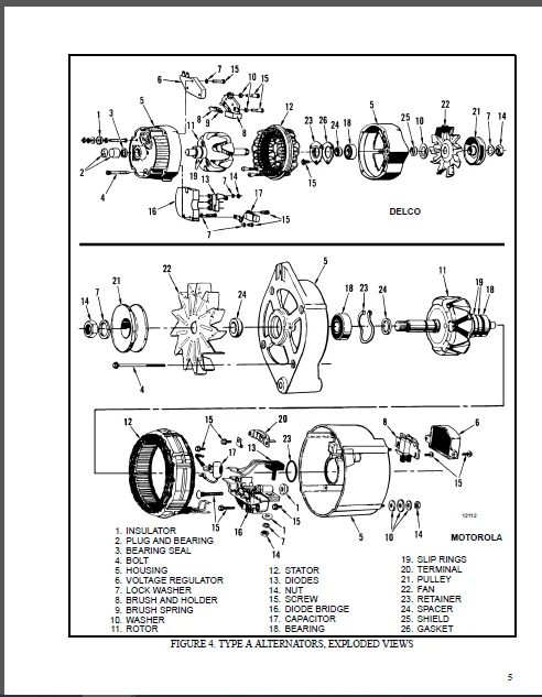
- • Do not check for current flow by making a spark because the electronic components can be damaged. NOTE: Information on alternators manufactured outside the United States is in the SRM (service repair manual) sections for lift trucks that use those alternators. DESCRIPTION (See FIGURE 1. and FIGURE 2.) NOTE: For this SRM section, the alternators are in two groups, Type A and Type B. The two types are very similar, but the Type A alternators have a set of three diodes (diode set) as well as the diode bridge.
- The Type B alternator has zener diodes as part of the diodes in the diode bridge. This alternator does not have a diode set, but does have an additional fan inside the rear housing. The basic operation of both types is very similar. The alternator generates an alternating current when the engine is running. The alternator is either ON or OFF. The alternator generates maximum current when it is ON and no current when it is OFF. The regulator switches the alternator between ON and OFF to get the average current needed to charge the battery. Alternator output is directly changed by engine speed and rotor field current. The alternating current is changed to a direct current by the diode bridge inside the alternator.
Table of Contents:
Hyster H40 60XL A177 service manual
INTRODUCTION..................................................................................................  1
	GENERAL...................................................................................................  1
	DESCRIPTION...............................................................................................  1
REPAIRS.......................................................................................................  3
	GENERAL...................................................................................................  3
	REMOVAL AND DISASSEMBLY (Type A)..........................................................................  3
	CLEANING..................................................................................................  3
	ASSEMBLY (Type A).........................................................................................  4
	REMOVAL AND DISAASSEMBLY (Type B).........................................................................  6
	CLEANING..................................................................................................  8
	ASSEMBLY (Type B).........................................................................................  8
	INSTALLATION (Type A and Type B)..........................................................................  9
CHECKS AND ADJUSTMENTS........................................................................................  9
	GENERAL...................................................................................................  9
	CHECK THE ALTERNATOR FOR LOW OUTPUT (Type A or Type B).................................................... 10
	CHECK THE ALTERNATOR FOR HIGH OUTPUT (Type A or Type B)................................................... 11
	CHECK THE CIRCUIT FOR THE BRUSHES......................................................................... 13
		Delco Alternators..................................................................................... 13
		Motorola Alternators.................................................................................. 13
	CHECK THE DIODES.......................................................................................... 13
	CHECK THE DIODE BRIDGE.................................................................................... 13
		Delco and Leece–Neville Alternators................................................................... 13
		Motorola Alternators.................................................................................. 13
	CHECK THE FIELD WINDING FOR THE ROTOR..................................................................... 14
	CHECK THE WINDINGS IN THE STATOR.......................................................................... 14
	CHECK THE VOLTAGE REGULATOR............................................................................... 15
TROUBLESHOOTING............................................................................................... 15
INTRODUCTION.................................................................................................. 16
	GENERAL................................................................................................... 16
	DESCRIPTION AND OPERATION................................................................................. 16
		Service and Parking Brakes............................................................................ 18
REPAIRS....................................................................................................... 18
	REMOVAL AND DISASSEMBLY................................................................................... 18
		Service and Parking Brakes............................................................................ 18
		Master Cylinder....................................................................................... 19
	CLEANING AND INSPECTION................................................................................... 20
	ASSEMBLY AND INSTALLATION................................................................................. 20
		Service and Parking Brakes............................................................................ 20
		Master Cylinder....................................................................................... 25
CHECKS AND ADJUSTMENTS........................................................................................ 25
	ADJUST THE SERVICE BRAKES................................................................................. 25
	ADJUST THE PARKING BRAKE.................................................................................. 26
		Units with Monotrol Pedal............................................................................. 26
	REMOVE THE AIR FROM THE BRAKE SYSTEM...................................................................... 27
	ADJUST THE BRAKE PEDAL AND INCHING PEDAL.................................................................. 27
	CHECK AND ADJUST THE NEUTRAL START SWITCH (Monotrol Control Only)......................................... 31
TROUBLESHOOTING............................................................................................... 33
SPECIFICATIONS................................................................................................ 34
LIFT TRUCK WEIGHTS*........................................................................................... 35
ENGINE SPECIFICATIONS......................................................................................... 35
ENGINE ELECTRICAL SPECIFICATIONS.............................................................................. 36
HYDRAULIC SPECIFICATIONS...................................................................................... 36
CAPACITIES.................................................................................................... 37
LIFT TRUCK TRAVEL SPEEDS...................................................................................... 37
TIRE SPECIFICATIONS........................................................................................... 37
MAST SPEEDS (Early A177* Units)............................................................................... 38
MAST SPEEDS (Later A177* Units)............................................................................... 38
MAST SPEEDS (B177* and C177* with Mazda M4-121G or Isuzu 240 Engines)......................................... 39
MAST SPEEDS (C177* with GM 4-181 or Isuzu 4JB1 Engines)....................................................... 39
TORQUE SPECIFICATIONS......................................................................................... 41
TORQUE SPECIFICATIONS......................................................................................... 42
COOLING SYSTEM................................................................................................ 44
	INTRODUCTION.............................................................................................. 44
	DESCRIPTION............................................................................................... 44
	RADIATOR.................................................................................................. 44
	RADIATOR CAP.............................................................................................. 44
	THERMOSTAT................................................................................................ 44
	WATER PUMP................................................................................................ 45
	FAN AND FAN SHROUD........................................................................................ 45
REPAIRS....................................................................................................... 45
	COOLING SYSTEM CHECKS..................................................................................... 45
		Exhaust Leaks......................................................................................... 45
	RADIATOR.................................................................................................. 45
		Checks................................................................................................ 45
		Cleaning The Radiator................................................................................. 45
		Drain The Cooling System.............................................................................. 47
		Fill The Cooling System............................................................................... 47
	WATER PUMP................................................................................................ 47
		Checks................................................................................................ 47
	THERMOSTAT................................................................................................ 48
		Checks................................................................................................ 48
	FAN AND FAN SHROUD........................................................................................ 48
TROUBLESHOOTING............................................................................................... 49
HYDRAULIC SCHEMATIC SYMBOLS................................................................................... 50
HYDRAULIC SYSTEM SCHEMATIC - FOR UNITS WITH WARNER TRANSMISSION............................................... 52
HYDRAULIC SYSTEM SCHEMATIC - FOR UNITS WITH HYSTER T41, T42, T43 TRANSMISSIONS................................ 54
TRANSMISSION HYDRAULIC SCHEMATIC - FOR UNITS WITH WARNER TRANSMISSION......................................... 55
TRANSMISSION HYDRAULIC SCHEMATIC - FOR UNITS WITH HYSTER T41, T42, T43 TRANSMISSION........................... 56
GASOLINE/LPG ENGINE WIRING DIAGRAM (G and LPG Rating)......................................................... 58
GASOLINE/LPG (SAFETY) ENGINE WIRING DIAGRAM (GS and LPS Rating)............................................... 60
GASOLINE/LPG ENGINE CABLE DIAGRAM (G and LPG Rating).......................................................... 62
DIESEL ENGINE WIRING DIAGRAM (D Rating)....................................................................... 64
DIESEL (SAFETY) ENGINE WIRING DIAGRAM (DS Rating)............................................................. 66
DIESEL ENGINE CABLE DIAGRAM (D Rating)........................................................................ 68
ELECTRICAL DIAGRAM, INSTRUMENT PANEL.......................................................................... 69
INTRODUCTION.................................................................................................. 70
	GENERAL................................................................................................... 70
	DESCRIPTION............................................................................................... 70
REPAIRS....................................................................................................... 71
	REMOVAL................................................................................................... 71
	CLEANING.................................................................................................. 71
	INSPECTION................................................................................................ 71
	ASSEMBLY.................................................................................................. 71
TROUBLESHOOTING............................................................................................... 74
SPECIFICATIONS................................................................................................ 74
INTRODUCTION.................................................................................................. 75
	GENERAL................................................................................................... 75
	DESCRIPTION............................................................................................... 75
		Starting System....................................................................................... 75
		Charging System....................................................................................... 75
		Vacuum Pump On Alternator (On Units With Brake Booster)............................................... 77
REPAIRS....................................................................................................... 78
	STARTER................................................................................................... 78
		Removal And Disassembly............................................................................... 78
		Assembly And Installation............................................................................. 78
	REPLACING GLOW PLUGS...................................................................................... 80
	ALTERNATOR (With Vaccum Pump)............................................................................. 80
		Removal And Disassembly............................................................................... 80
		Cleaning.............................................................................................. 82
		Assembly And Installation............................................................................. 82
	ALTERNATOR (Without Vacuum Pump).......................................................................... 83
		Removal And Disassembly............................................................................... 83
		Cleaning.............................................................................................. 85
		Assembly And Installation............................................................................. 85
	REGULATOR REPLACEMENT..................................................................................... 86
CHECKS........................................................................................................ 86
	GENERAL................................................................................................... 86
	STARTER................................................................................................... 86
		Starter Operation..................................................................................... 86
		Solenoid Coil Checks.................................................................................. 87
		Brush Length.......................................................................................... 87
		Brush Holder.......................................................................................... 87
		Armature.............................................................................................. 87
		Field Windings........................................................................................ 88
		Clutch And Bearings................................................................................... 88
	COLD START AID............................................................................................ 88
		Glow Plugs............................................................................................ 88
		Resistor.............................................................................................. 88
	CHARGING CIRCUIT.......................................................................................... 88
		Check For Low Output.................................................................................. 88
		Check Ford High Output................................................................................ 90
	ALTERNATOR................................................................................................ 90
		Rotor Resistance...................................................................................... 90
		Diodes Circuit........................................................................................ 90
		Rotor Coil............................................................................................ 91
		Stator Coil........................................................................................... 91
		Diode Assembly........................................................................................ 91
		Brushes And Bearings.................................................................................. 92
	REGULATOR (At Hydraulic Tank)............................................................................. 92
TROUBLESHOOTING............................................................................................... 93
INTRODUCTION.................................................................................................. 96
	GENERAL................................................................................................... 96
	DESCRIPTION............................................................................................... 96
		Starting System....................................................................................... 96
		Ignition System....................................................................................... 96
		Charging System....................................................................................... 97
REPAIR........................................................................................................ 99
	STARTER................................................................................................... 99
		Removal And Disassembly............................................................................... 99
		Assembly And Installation............................................................................. 99
	BALLAST RESISTOR RELAY (Earlier Production)...............................................................101
	DISTRIBUTOR (Earlier Production With Contact Points)......................................................101
		Removal And Disassembly...............................................................................101
		Assembly And Installation.............................................................................103
	COIL REPLACEMENT..........................................................................................103
	DISTRIBUTOR (Later Production with Electronic Ignition System)............................................103
		Removal And Disassembly...............................................................................103
		Assembly And Installation.............................................................................105
	ALTERNATOR (All Models)...................................................................................105
		Removal And Disassembly...............................................................................105
		Assembly And Installation.............................................................................106
	REGULATOR REPLACEMENT (Earlier Production)................................................................107
CHECKS AND ADJUSTMENTS........................................................................................108
	GENERAL...................................................................................................108
	STARTER...................................................................................................108
		Check Operation.......................................................................................108
		Check Brush Length....................................................................................109
		Check Brush Holder....................................................................................109
		Armature..............................................................................................109
		Field Windings........................................................................................109
		Clutch And Bearing....................................................................................109
	BALLAST RESISTOR RELAY (Earlier Production)...............................................................109
	DISTRIBUTOR...............................................................................................110
		Distributor Contact Clearance.........................................................................110
	SPARK PLUGS...............................................................................................111
	COIL AND BALLAST RESISTOR (Earlier Production)............................................................111
	ALTERNATOR................................................................................................111
		Check For Low Output (Alternator With Separate Regulator).............................................111
		Check For Low Output (Alternator With Integral Regulator).............................................113
		Check For High Output (Alternator With Separate Regulator)............................................114
		Check For High Output (Alternator With Integral Regulator)............................................114
		Rotor Resistance (Alternator with Separate Regulator).................................................114
		Diodes Circuit (Alternator with Separate Regulator)...................................................115
		Diode Assembly (Alternator With Separate Regulator)...................................................115
		Check The Diodes, Diode Trio (Alternator with Integral Regulator).....................................115
		Check The Rectifier Bridge (Alternator with Integral Regulator).......................................116
		Check Field Winding For The Rotor (All Alternators)...................................................116
		Check Windings In The Stator (All Alternators)........................................................117
		Brushes And Bearings..................................................................................117
		Check The Voltage Regulator (Alternator with Separate Regulator)......................................117
		Check The Voltage Regulator (Alternator with Integral Regulator)......................................118
	ADJUSTMENTS...............................................................................................118
TROBLESHOOTING................................................................................................119
INTRODUCTION..................................................................................................121
	GENERAL...................................................................................................121
	DESCRIPTION...............................................................................................121
REPAIRS.......................................................................................................121
	COUNTERWEIGHT.............................................................................................122
		Removal...............................................................................................122
		Installation..........................................................................................122
	MUFFLER...................................................................................................123
	HOOD......................................................................................................123
		Removal...............................................................................................123
		Installation..........................................................................................123
	RADIATOR AND COOLANT SYSTEM...............................................................................123
		Removal...............................................................................................123
		Installation..........................................................................................123
	OVERHEAD GUARD............................................................................................124
		Removal And Installation..............................................................................124
	OPERATOR RESTRAINT SYSTEM.................................................................................124
	ENGINE REMOVAL AND INSTALLATION...........................................................................125
		Removal of the Engine and Transmission................................................................125
		Installation of the Engine and Transmission...........................................................129
	FUEL AND HYDRAULIC TANKS..................................................................................131
		Inspection............................................................................................131
		Repairs, Small Leaks..................................................................................131
		Repairs, Large Leaks..................................................................................131
		Cleaning..............................................................................................131
		Steam Method Of Cleaning..............................................................................131
		Chemical Solution Method of Cleaning..................................................................132
		Additional Preparations For Repair....................................................................132
	SAFETY LABELS.............................................................................................132
	CAB.......................................................................................................134
		Cab Replacement.......................................................................................134
		Window Replacement....................................................................................134
		Windshield Wipers and Heater..........................................................................136
THE CARBURETOR, (MAZDA M4-121G ENGINE)........................................................................137
	DESCRIPTION...............................................................................................137
	REPAIRS, CARBURETOR.......................................................................................138
		Removal...............................................................................................138
		Cleaning..............................................................................................141
		Inspection............................................................................................141
		Assembly..............................................................................................141
		Installation..........................................................................................143
	CHECKS AND ADJUSTMENTS....................................................................................143
		Carburetor, Idle Speed And Mixture Adjustment.........................................................143
		Adjust The Governor...................................................................................144
	ADJUST THE THROTTLE LINKAGE...............................................................................145
SPECIFICATIONS................................................................................................145
TROUBLESHOOTING...............................................................................................146
INTRODUCTION..................................................................................................148
	GENERAL...................................................................................................148
	DESCRIPTION...............................................................................................150
		Hydraulic System......................................................................................150
		Gear Pump Assembly....................................................................................150
		Flow Control Valve....................................................................................151
		Relief Valve (Early Model)............................................................................151
		Relief Valve (Later Model)............................................................................151
	OPERATION.................................................................................................153
		Hydraulic System......................................................................................153
		Gear Pump.............................................................................................153
		Flow Control Valve....................................................................................153
		Relief Valve (Early Model)............................................................................153
		Relief Valve (Later Model)............................................................................153
REPAIR........................................................................................................155
	GEAR PUMP ASSEMBLY........................................................................................155
		Removal and Disassembly...............................................................................155
		Assembly and Installation.............................................................................156
CHECKS AND ADJUSTMENTS........................................................................................156
	CHECK AND ADJUST STEERING RELIEF PRESSURE.................................................................156
	CHECK GEAR PUMP FOR CORRECT FLOW..........................................................................157
TROUBLESHOOTING...............................................................................................157
INTRODUCTION..................................................................................................159
	NOMENCLATURE, THREADS.....................................................................................159
	STRENGTH IDENTIFICATION...................................................................................160
TABLE 1. BOLTS AND SCREWS.....................................................................................160
TABLE 2. STUDS AND NUTS.......................................................................................161
TABLE 3. TORQUE NUTS..........................................................................................162
TABLE 4. TORQUE NUTS WITH NYLON INSERT........................................................................163
TABLE 5. TORQUE VALUES FOR INCH FASTENERS.....................................................................164
TABLE 6. TORQUE VALUES FOR METRIC FASTENERS...................................................................165
INTRODUCTION..................................................................................................168
	GENERAL...................................................................................................168
DESCRIPTION...................................................................................................168
	GENERAL...................................................................................................168
	STEERING COLUMN GAUGES, METERS AND INDICATORS.............................................................171
	LED DISPLAY PANEL.........................................................................................171
		Battery Discharge Indicators..........................................................................171
		Brush Wear Indicators.................................................................................172
		Motor Temperature Indicators..........................................................................173
	"LX" SERIES DISPLAY PANEL.................................................................................174
		Hourmeter Functions...................................................................................175
		Battery Indicator Function............................................................................175
		Status Code Function..................................................................................175
	"ZX" SERIES DISPLAY PANELS................................................................................175
		Display Panel.........................................................................................176
		Basic Display Panels..................................................................................176
		Performance Display...................................................................................178
		Brush Wear Indicators.................................................................................181
CHECKS AND ADJUSTMENTS........................................................................................181
	GENERAL...................................................................................................181
REPLACEMENT...................................................................................................182
	GENERAL...................................................................................................182
	METER REPLACEMENT.........................................................................................182
	SENDER REPLACEMENT........................................................................................183
		Fuel Level Sender.....................................................................................183
		Pressure And Temperature Sender.......................................................................183
	I.T.W. DISPLAY PANEL......................................................................................184
		Removal...............................................................................................184
	DISPLAY PANELS FOR THE EV - 100/200ZX MOTOR CONTROLLERS, COLUMN MOUNT.....................................185
		Removal...............................................................................................185
		Replacing Display Panel Assembly......................................................................185
		Indicator LEDs........................................................................................185
		Battery Indicators....................................................................................185
		Digital Display (Performance Disply Panel Only).......................................................185
		Status Code Or Performance Level Switches And Indicator LEDs (Performance Display Panel Only).........185
		Replacing Parts Of The Basic Display Panel............................................................186
		Replacing Parts Of The Performance Display Panel......................................................188
	DISPLAY PANELS FOR THE EV-100/200ZX MOTOR CONTROLLERS, DASH MOUNT.........................................188
		Removal And Replacement...............................................................................188
SPECIFICATIONS................................................................................................189
TROUBLESHOOTING...............................................................................................190
INTRODUCTION .................................................................................................191
	GENERAL ..................................................................................................191
	DESCRIPTION ..............................................................................................191
	FUEL SYSTEM ..............................................................................................192
		Description ..........................................................................................192
		Operation, Fuel Injection Pump, Model VE .............................................................194
		Operation, Fuel Injection Pump, Model PE4A ...........................................................195
		Pneumatic Governor For Fuel Injection Pump, Model PE4A ...............................................196
		Inlet Manifold For Fuel Injection Pump, Model PE4A ...................................................197
REPAIRS ......................................................................................................198
	FUEL INJECTION PUMP (ALL MODELS) .........................................................................198
		Removal ..............................................................................................198
		Installation .........................................................................................198
	REMOVAL AND INSTALLATION OF THE ENGINE ...................................................................198
	CYLINDER HEAD AND VALVE MECHANISM ........................................................................198
		Cylinder Head, Removal ...............................................................................198
		Valve Guides, Replacement ............................................................................199
		Cylinder Head, Inspection And Repair .................................................................200
		Combustion Chamber Plugs, Inspection And Repair ......................................................200
		Combustion Chamber Plugs, Installation ...............................................................200
		Valves, Inspection And Repair ........................................................................201
		Valve Seat, Inspection ...............................................................................201
		Valve Seat, Removal ..................................................................................202
		Valve Seat, Installation .............................................................................202
		Valve Spring, Inspection .............................................................................202
		Rocker Arms, Inspection And Assembly .................................................................202
		Installation Of The Cylinder Head ....................................................................203
	TIMING GEAR CASE .........................................................................................204
		Removal ..............................................................................................204
		Installation .........................................................................................204
	CAMSHAFT .................................................................................................206
		Removal ..............................................................................................206
		Inspection ...........................................................................................206
		Camshaft Bearings ....................................................................................207
		Cam Followers ........................................................................................207
	CAMSHAFT, INSTALLATION ...................................................................................207
	CRANKSHAFT AND MAIN BEARINGS .............................................................................208
		Crankshaft, Removal ..................................................................................208
		Crankshaft, Inspection And Repair ....................................................................208
		Main Bearings ........................................................................................208
		Pilot Bearing ........................................................................................209
		Crankshaft, Installation .............................................................................209
	FLYWHEEL AND RING GEAR, H2.00–3.20XM (H40–65XM) ..........................................................211
		Flywheel, Removal ....................................................................................211
		Ring Gear, Replacement ...............................................................................211
		Flywheel, Installation ...............................................................................211
	PISTONS AND CONNECTING RODS ..............................................................................212
		Pistons And Connecting Rods, Removal .................................................................212
		Disassembly ..........................................................................................212
		Pistons, Inspection And Repair .......................................................................213
		Piston Rings, Inspection And Repair ..................................................................213
		Piston Pins, Inspection And Repair ...................................................................214
		Connecting Rods, Inspection And Repair ...............................................................215
		Pistons And Connecting Rods, Assembly And Installation ...............................................215
	CYLINDER BLOCK AND CYLINDER LINERS .......................................................................215
		Cylinder Liners, Inspection ..........................................................................215
		Replacement Of A Cylinder Liner ......................................................................216
	LUBRICATION SYSTEM .......................................................................................217
		Oil Pump, Removal And Disassembly ....................................................................217
		Oil Pump, Inspection .................................................................................217
		Oil Pump, Assembly And Installation ..................................................................218
		Oil Filter ...........................................................................................218
	COOLING SYSTEM ...........................................................................................219
		Coolant Pump, Removal ................................................................................219
		Coolant Pump, Disassembly ............................................................................219
		Coolant Pump, Assembly And Installation ..............................................................219
		Thermostat, Replacement ..............................................................................220
CHECKS AND ADJUSTMENTS .......................................................................................220
	VALVE CLEARANCE ADJUSTMENT ...............................................................................220
	CHECK THE TIMING OF THE FUEL INJECTION PUMP, MODEL VE ....................................................221
	CHECK THE TIMING OF THE FUEL INJECTION PUMP, MODEL PE4A ..................................................222
	FUEL INJECTORS ...........................................................................................222
		Fuel Injectors, Removal ..............................................................................223
		Fuel Injectors, Inspection ...........................................................................223
		Fuel Injectors, Installation .........................................................................224
	DIESEL FUEL FILTERS ......................................................................................224
		Filter Replacement, Models With A Water Separator ....................................................224
		Filter Replacement, Models Without A Water Separator .................................................225
		Filter For The Fuel Injection Pump, Model PE4A .......................................................225
	REMOVE AIR FROM THE FUEL SYSTEM ..........................................................................225
		Throttle Linkage, Adjustment .........................................................................226
		Idle Speed, Adjustment ...............................................................................226
		Check The Elements For The Cold Start Aid System .....................................................226
ENGINE SPECIFICATIONS ........................................................................................226
TORQUE SPECIFICATIONS ........................................................................................228
SAFETY PROCEDURES WHEN WORKING NEAR THE MAST..................................................................229
	SAFETY PROCEDURES WHEN WORKING NEAR THE MAST..............................................................229
LIFT CYLINDERS................................................................................................232
	GENERAL...................................................................................................232
	DESCRIPTION...............................................................................................232
		Lowering Control Valve................................................................................232
		Cylinders (General)...................................................................................235
		Cylinders (H520-620B,H700-800A).......................................................................237
		Cylinders (H360-460B).................................................................................238
		Cylinders (Two-Speed).................................................................................238
REPAIRS.......................................................................................................239
	REMOVAL OF THE LIFT CYLINDER WITHOUT REMOVING THE MAST....................................................239
		Standard Masts with the Main Lift Cylinder Fastened to the Crossmember of the Inner Mast..............239
		Standard and Full Free-Lift Masts with the Lift Cylinder to a Crosshead...............................243
		Masts that have Two Cylinders, A Main Lift Cylinder  and a Free-Lift Cylinder.........................241
	DISASSEMBLY...............................................................................................241
	ASSEMBLY..................................................................................................243
	INSTALLATION OF THE LIFT CYLINDER IN THE MAST.............................................................243
		Standard Masts with the Main Lift Cylinder Fastened to the Crossmember of the Inner Mast..............243
		Standard and Full-Free-Lift Masts with the Lift Cylinder Fastened to a Crosshead......................243
	CHEVRON PACKING...........................................................................................244
LIFT CYLINDERS FOR VISTA MASTS................................................................................247
	DESCRIPTION...............................................................................................247
		Lowering Control Valve................................................................................249
	REMOVAL...................................................................................................250
	DISASSEMBLY...............................................................................................250
	ASSEMBLY..................................................................................................250
	INSTALLATION..............................................................................................251
		Main Lift Cylinders...................................................................................251
		Free-Lift Cylinders...................................................................................251
CHECKS AND ADJUSTMENTS........................................................................................252
	CHECK FOR LEAKS IN LIFT SYSTEM............................................................................252
TROUBLESHOOTING...............................................................................................253
SPECIFICATIONS................................................................................................254
THE LPG FUEL SYSTEM (IMPCO CA 50, CA 100).....................................................................255
	GENERAL...................................................................................................255
	DESCRIPTION...............................................................................................255
		Fuel Tank.............................................................................................256
		Fuel Filter And Fuel Valve Unit.......................................................................257
		Vaporizer.............................................................................................257
		The IMPCO CA 100 Carbureto............................................................................259
		IMPCO CA 50 Carburetor................................................................................261
		The Governor (GM Engines Only)........................................................................262
		Governor With Electronic Controller...................................................................263
REPAIRS.......................................................................................................264
	LPG TANK..................................................................................................264
		Removal...............................................................................................264
		Installation..........................................................................................265
	REPLACE THE HOSES.........................................................................................265
	HYDROSTATIC RELIEF VALVE..................................................................................265
		Removal and Installation..............................................................................265
	FILTER UNIT...............................................................................................266
		Replacement Of the Fuel Filter Element................................................................266
		Replacement of the Diaphragm and Fuel Valve...........................................................267
	VAPORIZER.................................................................................................267
		Removal...............................................................................................267
		Disassembly...........................................................................................267
		Cleaning..............................................................................................267
		Inspection............................................................................................267
		Assembly..............................................................................................269
		Installation..........................................................................................269
	CARBURETOR (IMPCO CA 100).................................................................................271
		Removal...............................................................................................271
		Disassembly...........................................................................................271
		Cleaning..............................................................................................271
		Assembly..............................................................................................271
		Installation..........................................................................................274
	CARBURETER (IMPCO CA 50)..................................................................................273
		Removal...............................................................................................273
		Disassembly...........................................................................................273
		Cleaning..............................................................................................274
		Inspection............................................................................................274
		Assembly (See FIGURE 26.).............................................................................274
		Installation..........................................................................................274
CHECKS AND ADJUSTMENTS........................................................................................275
	CHECK THE FILTER UNIT.....................................................................................275
	CHECK THE VAPORIZER.......................................................................................275
		Pressure Reducer Valve................................................................................275
		Vapor Valve...........................................................................................275
	ADJUST THE CARBURETOR.....................................................................................275
		Idle Mixture..........................................................................................275
		Idle Speed............................................................................................275
		Power Mixture.........................................................................................275
	ADJUST THE GOVERNOR (GM Engines Only).....................................................................276
		Checks................................................................................................276
		Main Adjusting Screw..................................................................................276
		Secondary Adjusting Screw.............................................................................276
		AISAN Governor........................................................................................277
		Adjustment, AISAN Governor............................................................................277
TROUBLESHOOTING...............................................................................................278
INTRODUCTION..................................................................................................282
	GENERAL...................................................................................................282
	DESCRIPTION...............................................................................................282
	OPERATION.................................................................................................283
		Lift Section..........................................................................................284
		Tilt Section..........................................................................................284
		Relief Valve..........................................................................................286
	SOLENOID VALVE FOR AUXILIARY FUNCTION.....................................................................287
		Operation.............................................................................................287
REPAIRS.......................................................................................................287
	MAIN CONTROL VALVE........................................................................................287
		Removal and Disassembly...............................................................................287
		Cleaning and Inspection...............................................................................288
		Assembly..............................................................................................288
		Installation..........................................................................................288
	SOLENOID VALVE FOR AUXILIARY FUNCTION.....................................................................288
		Removal and Disassembly...............................................................................288
		Assembly and Installation.............................................................................290
CHECKS AND ADJUSTMENTS........................................................................................290
	PRESSURE RELIEF VALVES....................................................................................290
		Primary Relief Valve..................................................................................290
		Seconday Relief Valve.................................................................................291
	CONTROL LEVER ARRANGEMENT.................................................................................291
TROUBLESHOOTING...............................................................................................294
SPECIFICATIONS................................................................................................296
INTRODUCTION..................................................................................................297
	GENERAL...................................................................................................297
	DESCRIPTION...............................................................................................297
		Upright Assembly......................................................................................297
		Upright Mounts........................................................................................298
		Carriage..............................................................................................299
	OPERATION.................................................................................................299
		Standard Upright......................................................................................299
		Three Stage Uprights..................................................................................299
SAFETY PROCEDURES WHEN WORKING NEAR THE MAST..................................................................302
INTRODUCTION..................................................................................................303
	GENERAL...................................................................................................303
	REPAIR....................................................................................................303
		Forks.................................................................................................303
		Forks, Adjustment.....................................................................................303
		Forks, Removal And Installation.......................................................................304
		Hook Fork, Removal....................................................................................304
		Hook Fork, Installation...............................................................................304
	CARRIAGE..................................................................................................304
		Removal...............................................................................................304
		Installation..........................................................................................305
	MAST......................................................................................................305
		Removal...............................................................................................305
		Disassembly, Standard Mast............................................................................306
		Disassembly, Three-Stage Mast.........................................................................306
		Cleaning And Inspection...............................................................................310
		Assembly..............................................................................................311
		Installation..........................................................................................311
	SIDE-SHIFT CARRIAGE.......................................................................................311
		Removal...............................................................................................311
		Repairs...............................................................................................313
		Installation..........................................................................................313
	CHECKS AND ADJUSTMENTS....................................................................................313
		Check For Leaks In The Lift Sytem.....................................................................313
		Leakage Outside the Hydraulic Lift System.............................................................313
		Leakage Inside the Hydraulic Lift System..............................................................313
		Check the lift cylinder for inside leakage............................................................313
		Check For Leaks In The Tilt System....................................................................313
	ADJUST THE TILT CYLINDER STROKE AND THE BACKWARD TILT ANGLE...............................................313
	LIFT CHAIN ADJUSTMENTS....................................................................................314
	MAST ADJUSTMENTS..........................................................................................315
	CARRIAGE ADJUSTMENT.......................................................................................316
	HEADER HOSE ARRANGEMENT...................................................................................316
		Three-Stage Header Hoses..............................................................................316
TROUBLESHOOTING...............................................................................................318
MAZDA M4-121G ENGINE..........................................................................................319
	GENERAL...................................................................................................319
	DESCRIPTION...............................................................................................320
	REMOVAL AND INSTALLATION OF THE ENGINE....................................................................320
	CYLINDER HEAD AND VALVE MECHANISM.........................................................................320
		Cylinder Head, Removal................................................................................320
		Cylinder Head, Inspection and Repairs.................................................................321
		Rocker Arm Assembly...................................................................................321
		Valve Guides..........................................................................................321
		Valve Seats...........................................................................................322
		Valves................................................................................................322
		Valve Springs.........................................................................................322
		Cylinder Head, Installation...........................................................................322
	TIMING GEAR CASE, REMOVAL.................................................................................323
	TIMING GEAR CASE, INSTALLATION............................................................................324
	CAMSHAFT..................................................................................................324
		Removal...............................................................................................324
		Inspection............................................................................................325
		Cam Followers, Inspection.............................................................................325
		Installation..........................................................................................325
	CRANKSHAFT AND MAIN BEARINGS..............................................................................325
		Crankshaft, Removal...................................................................................325
		Crankshaft, Inspection And Repair.....................................................................326
		Main Bearings.........................................................................................327
		Crankshaft, Installation..............................................................................327
	PISTONS AND CONNECTING RODS...............................................................................328
		Removal...............................................................................................328
		Disassembly...........................................................................................328
		Pistons, Inspection And Repair........................................................................328
		Piston Rings..........................................................................................329
		Piston Pin and Bushing................................................................................329
		Connecting Rods and Bearings, Inspection..............................................................329
		Pistons and Connecting Rods, Assembly.................................................................329
		Pistons and Connecting Rods, Installation.............................................................330
	CYLINDER BLOCK AND CYLINDER LINERS........................................................................330
		Cylinder Block, Repairs...............................................................................330
		Cylinder Liners.......................................................................................330
	DISTRIBUTOR...............................................................................................331
		Removal...............................................................................................331
		Installation..........................................................................................331
	OIL PUMP..................................................................................................333
		Removal...............................................................................................333
		Repairs...............................................................................................333
		Installation..........................................................................................334
	GOVERNOR..................................................................................................334
		Description...........................................................................................334
		Removal...............................................................................................334
		Disassembly...........................................................................................335
		Assembly..............................................................................................336
		Installation..........................................................................................337
	COOLANT PUMP..............................................................................................337
		Removal...............................................................................................337
		Disassembly and Repair................................................................................338
		Assembly..............................................................................................338
		Installation..........................................................................................339
	FLYWHEEL..................................................................................................339
		Repairs...............................................................................................339
		Installation..........................................................................................339
CHECKS AND ADJUSTMENTS........................................................................................339
	ADJUST THE VALVES.........................................................................................339
	ADJUST THE THROTTLE LINKAGE...............................................................................340
ENGINE SPECIFICATIONS.........................................................................................340
	ENGINE SPECIFICATIONS.....................................................................................340
		Engine Data...........................................................................................340
		Cooling System........................................................................................340
		Cylinder Head and Valve Mechanism.....................................................................340
		Camshaft..............................................................................................342
		Timing Gear...........................................................................................343
		Camshaft..............................................................................................343
		Connecting Rods.......................................................................................343
		Cylinder Liners.......................................................................................343
		Pistons...............................................................................................343
		Lubrication System....................................................................................344
		Fuel Pump.............................................................................................344
	TORQUE SPECIFICATIONS.....................................................................................345
TROUBLESHOOTING...............................................................................................346
PERIODIC MAINTENANCE..........................................................................................350
	GENERAL...................................................................................................350
		Serial Number Data....................................................................................350
	HOW TO MOVE A DISABLED LIFT TRUCK.........................................................................351
		How To Tow the Lift Truck.............................................................................351
	HOW TO PUT A LIFT TRUCK ON BLOCKS.........................................................................351
		How To Raise the Drive Tires..........................................................................351
		How To Raise the Steering Tires.......................................................................352
MAINTENANCE PROCEDURES........................................................................................356
EVERY 8 HOURS OR DAILY........................................................................................356
	HOW TO MAKE CHECKS WITH THE ENGINE STOPPED................................................................356
		Engine Oil............................................................................................356
		Drive Belts...........................................................................................356
		Cooling System........................................................................................356
		Battery...............................................................................................357
		Fuel System...........................................................................................359
		Air Filter............................................................................................359
		Hydraulic System Oil..................................................................................359
		Tires and Wheels......................................................................................360
		Forks.................................................................................................360
		Forks, Adjustment.....................................................................................361
		Forks, Removal And Installation.......................................................................361
		Inspection Of Forks, Mast, and Lift Chains............................................................362
		Safety Labels.........................................................................................363
		Operator Restraint System.............................................................................363
	HOW TO MAKE CHECKS WITH THE ENGINE RUNNING................................................................364
		Gauges, Lights, Horn, and Fuses.......................................................................364
		Fuel Filter, Diesel Engine............................................................................365
		How To Drain The Water From The Fuel Filter...........................................................365
		Oil Level, Powershift Transmission....................................................................365
		Control Levers and Pedals.............................................................................365
		Lift System Operation.................................................................................365
		Inching/Brake Pedal...................................................................................366
		Service Brakes........................................................................................366
		Parking Brake.........................................................................................366
		Steering System.......................................................................................366
EVERY 250 HOURS OR TWO MONTHS.................................................................................367
	ENGINE OIL AND FILTER.....................................................................................367
		Mazda, GM, And Later Production Isuzu Engines.........................................................367
		Earlier Production Isuzu C240 Engines.................................................................367
	GOVERNOR, MAZDA ENGINE....................................................................................368
	DRIVE BELTS...............................................................................................368
		Mazda Engine..........................................................................................368
		Isuzu, GM 4-181, And GM 4-153 Engines.................................................................368
	BRAKE FLUID...............................................................................................369
	HYDRAULIC TANK BREATHER, CLEAN AND CHECK..................................................................369
	FORKS, CHECK FOR WEAR AND DAMAGE..........................................................................369
	LIFT CHAINS...............................................................................................369
		Lubrication...........................................................................................369
		Check For Wear........................................................................................369
	MAST, LUBRICATION.........................................................................................370
	TIE ROD ENDS AND PIVOT SHAFT, STEERING AXLE...............................................................370
	CONTROL LEVERS AND PEDALS, LUBRICATION....................................................................371
	FUEL SYSTEM, CHECKS AND ADJUSTMENTS.......................................................................371
		Idle Speed, Diesel....................................................................................371
		LPG Carburetor........................................................................................372
		Gasoline Carburetor...................................................................................372
EVERY 1000 HOURS OR SIX MONTHS................................................................................373
	DIESEL FUEL FILTER........................................................................................373
		Filter Replacement, Models Without A Water Separator..................................................374
		Filter Replacement, Models With A Water Separator.....................................................374
		Remove Air from the Diesel Fuel System................................................................374
	DIFFERENTIAL..............................................................................................375
	VALVE CLEARANCE ADJUSTMENT................................................................................375
	IGNITION SYSTEM, MAZDA AND GM ENGINES.....................................................................375
	PCV VALVE AND FILTER......................................................................................377
EVERY 2000 HOURS OR YEARLY....................................................................................377
	HYDRAULIC SYSTEM..........................................................................................377
		Replace the Hydraulic Oil and Filter..................................................................377
	POWERSHIFT TRANSMISSION...................................................................................377
	COOLING SYSTEM............................................................................................378
	SERVICE BRAKES............................................................................................378
	DIFFERENTIAL..............................................................................................378
	WHEEL BEARINGS............................................................................................379
		Steering Wheels, lubrication..........................................................................379
		Drive Wheels, Lubrication.............................................................................379
	GASOLINE FUEL FILTER, REPLACEMENT.........................................................................379
	PCV VALVE, GM ENGINES.....................................................................................379
	LPG FILTER, REPLACEMENT...................................................................................379
	FILTER FOR THE FUEL INJECTION PUMP, MODEL PE4A............................................................379
GENERAL PROCEDURES............................................................................................380
	CHECK THE HOOD LATCH......................................................................................380
	LIFT CHAIN ADJUSTMENTS....................................................................................380
	SAFETY PROCEDURES WHEN WORKING NEAR THE MAST..............................................................382
	CHECK FOR LEAKS IN THE LIFT AND TILT SYSTEM...............................................................383
		Check the Lift Cylinders for Leaks....................................................................383
		Check the Tilt Cylinders for Leaks....................................................................383
	FUEL INJECTORS............................................................................................384
	WELDING REPAIRS...........................................................................................384
	CHANGES TO THE OVERHEAD GUARD.............................................................................384
	WHEELS AND TIRES..........................................................................................384
		Solid Rubber Tires (Press-on).........................................................................384
		Install The Wheels....................................................................................385
		Pneumatic Tires, Remove The Wheels From The Lift Truck................................................386
		Pneumatic Tires, Remove the Tire From The Wheel.......................................................386
		Pneumatic Tires, Install The Wheel In The Tire........................................................387
		Pneumatic Tires, Add Air To The Tires.................................................................388
		Pneumatic Tires, Install the Wheels...................................................................389
		Pneumatic Tires, Installation Procedures, Dual Drive Wheels...........................................389
	SOLID RUBBER TIRES THAT LOOK LIKE PNEUMATIC TIRES.........................................................390
		Remove The Wheels From The Lift Truck.................................................................390
		Remove The Tire From The Wheel........................................................................390
		Install The Tire On The Wheel.........................................................................391
REFERENCE TABLE...............................................................................................392
INTRODUCTION..................................................................................................393
	General...................................................................................................393
DESCRIPTION AND OPERATION.....................................................................................393
	General...................................................................................................393
	Torque Converter..........................................................................................394
		Description...........................................................................................394
		Operation.............................................................................................394
	Clutch Assemblies.........................................................................................396
		Description...........................................................................................396
		Operation.............................................................................................397
	Hydraulic System..........................................................................................397
		General...............................................................................................397
	Oil Pump and Front Cover..................................................................................398
		Torque Converter Regulator............................................................................398
		Oil Cooler By-Pass....................................................................................398
	Control Valve.............................................................................................398
		General...............................................................................................398
	Differential..............................................................................................403
	Oil Flow Diagrams.........................................................................................404
		Neutral...............................................................................................404
		Forward...............................................................................................406
		Forward-Inching.......................................................................................408
		Reverse...............................................................................................410
INTRODUCTION..................................................................................................412
	GENERAL...................................................................................................412
DESCRIPTION AND OPERATION.....................................................................................413
	GENERAL...................................................................................................413
	TORQE CONVERTER...........................................................................................413
		Description...........................................................................................413
		Operation.............................................................................................413
	CLUTCH ASSEMBLIES.........................................................................................416
		Description...........................................................................................416
		Operation.............................................................................................418
	HYDRAULIC SYSTEM..........................................................................................418
		General...............................................................................................418
	CONTROL VALVE.............................................................................................418
		Regulator for Clutch Pressure.........................................................................421
		Inching Spool Assembly................................................................................421
		Direction Spool.......................................................................................421
		MONOTROL Control Valve................................................................................421
		Neutral Start Switch, MONOTROL Pedal Only.............................................................422
		Neutral Start Switch, Direction Control Lever Only....................................................422
		Modulator Circuit.....................................................................................422
		Regulator for the Toruqe Converter....................................................................423
		By-Pass Valve for the Oil Cooler......................................................................423
	DIFFERENTIAL..............................................................................................424
	OIL FLOW DIAGRAMS.........................................................................................424
INTRODUCTION..................................................................................................433
	GENERAL...................................................................................................433
REPAIRS.......................................................................................................435
	REPAIRS...................................................................................................435
		Torque Converter, Removal.............................................................................435
		Torque Converter, Installation........................................................................435
		Front Cover And Transmission Pump, Removal and Disassembly............................................436
		Front Cover And Transmission Pump, Assembly and Installation..........................................436
		Clutch Assemblies, Removal and Disassembly............................................................437
		Clutch Assemblies, Inspection.........................................................................440
		Clutch Assemblies, Assembly and Installation..........................................................441
		Differential, Removal and Disassembly.................................................................444
		Differential, Inspection..............................................................................446
		Differential, Assembly And Installation...............................................................446
	CONTROL VALVE.............................................................................................456
		Control Valve, Removal and Disassembly................................................................456
		Control Valve, Inspection.............................................................................456
		Control Valve, Assembly and Installation..............................................................458
		MONOTROL Pedal, Removal and Disassembly...............................................................460
		MONOTROL Pedal, Assembly and Installation.............................................................460
CHECKS AND ADJUSTMENTS........................................................................................462
	Stall Test................................................................................................462
	Adjustment Of The Direction Control Linkage...............................................................463
	Adjustment Of The Brake Pedal And Inching Pedal (Serial Number Codes A177, A187, B10, and C1).............464
	Adjustment Of The Direction Control Linkage (Serial Number Codes B177, C177, B187, and C187)..............467
	Test The Direction Control Linkage (Serial Number Codes B177, C177, B187, and C187).......................468
	Adjustment Of The Inching/Brake Pedal (Serial Number Codes B177, C177, B187, and C187)....................469
	Adjustment Of The Neutral Start Switch, MONOTROL Pedal (Serial Number Codes B177, C177, B187 and C187)....473
	Test The Neutral Start Switch, MONOTROL Pedal (Serial Number Codes B177, C177, B187, and C187)............474
	Check The Oil Pressures...................................................................................474
	Check The Relief Valve for the Transmission Pump..........................................................474
	Check The Clutch Pressure.................................................................................474
	Check The Torque Converter Regulator......................................................................475
	Check The Oil Pressure from the Oil Cooler................................................................475
	Check The Modulator Pressure..............................................................................476
TROUBLESHOOTING...............................................................................................476
TROUBLESHOOTING, PRESSURE TESTS...............................................................................478
INTRODUCTION..................................................................................................481
	General...................................................................................................481
		Removal of The Transmission...........................................................................481
		Installation of the Transmission......................................................................481
REPAIRS.......................................................................................................483
	Torque Converter..........................................................................................483
	Front Cover and Oil Pump..................................................................................483
	Clutch Assemblies.........................................................................................485
	Differential..............................................................................................493
	Control Valve.............................................................................................502
CHECKS AND ADJUSTMENTS........................................................................................504
	Stall Test................................................................................................504
	Adjusting the Direction Control Linkage...................................................................505
	Adjusting the Brake and Inching Pedals....................................................................506
	Checking the Oil Pressures................................................................................508
SPECIFICATIONS................................................................................................510
TROUBLESHOOTING...............................................................................................510
Please Note:
- This is the SAME exact manual used by your dealers to fix your vehicle.
- The same can be yours in the next 2-3 mins as you will be directed to the download page immediately after paying for the manual.
- Any queries / doubts regarding your purchase, please feel free to contact [email protected]
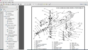
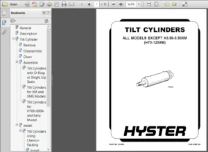
Sincere Vincenzo –
ease of use