
Hyundai 16B-9F 18B-9F 20B-9F Forklift Truck Parts Manual PDF Download
Original price was: $44.95.$29.95Current price is: $29.95.
Complete illustrated parts catalog for the Hyundai 16B-9F, 18B-9F and 20B-9F electric forklift trucks. Exploded diagrams, part numbers, quantities and serial number applicability for the full 16/18/20B-9F series, delivered as an instant PDF download.
Description
This Hyundai 16B-9F, 18B-9F and 20B-9F forklift truck parts manual is the complete illustrated parts catalog for the Hyundai 16/18/20B-9F series of electric counterbalance forklifts. Published 12 OCT. 2016 and referenced to chassis number HIK HHE07600039, it documents every assembly on the machine, from the traction and pump motors through the hydraulic control valve stacks to the mast, carriage and counterweight. The Hyundai 16/18/20B-9F parts manual is bilingual, with part names and system descriptions printed in both English and Korean.
Each assembly is presented as an exploded illustration with callouts keyed to a parts table that lists the item number, part number, description, quantity per machine, applicable serial number range and interchangeability code. For anyone maintaining, repairing or restoring a 16B-9F, 18B-9F or 20B-9F, this is the reference that lets you find the correct part the first time.
File Details
- Manual type: Illustrated parts manual
- Brand: Hyundai Heavy Industries
- Models covered: 16B-9F, 18B-9F, 20B-9F
- Language: English and Korean
- Page count: 337
- File format: PDF
- Date: 12 OCT. 2016
- Chassis reference: HIK HHE07600039
Chapters Covered
- 1. Electric System
- 2. Hydraulic System
- 3. Hydraulic Components
- 4. Power Train System
- 5. Steering & Control System
- 6. Structure
- 7. Attachment
- Numerical Part Index
1. Electric System
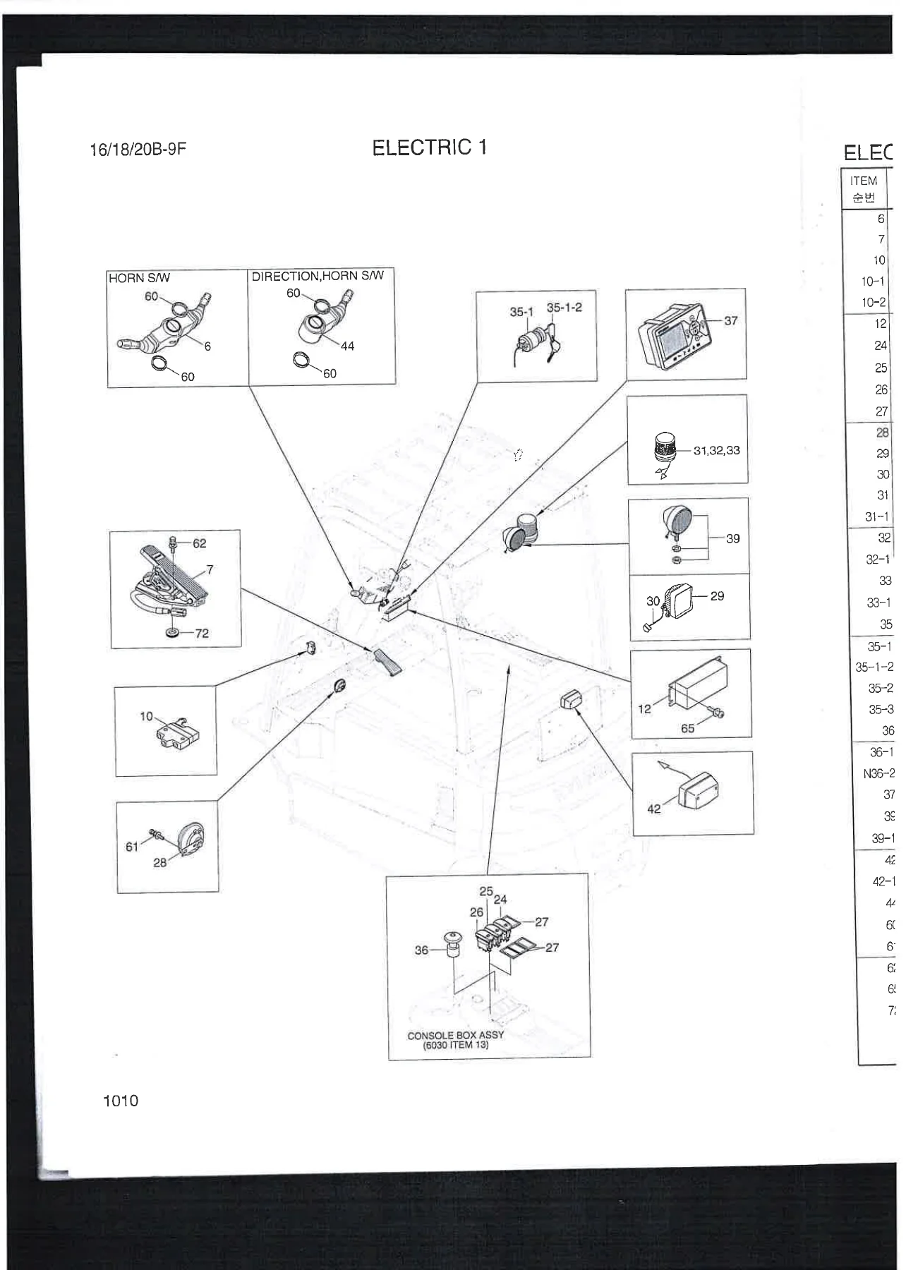
The largest section of the manual, covering the complete electrical system in three sub-groups. Electric 1 details the combination switch, direction switch, accelerator assembly, parking switch, micro switch, DC-DC converter, beacon and work lamp switches, LED work lamps, key switch, emergency switch, display and license lamp. Electric 2 covers the traction motor, pump motor, fan, safety cover and static strap. Electric 3 lists the dual AC controller, ACE controller, relays, back buzzer, fan assembly, contactors, fuse box and flasher unit. The cable and harness chapters give battery cables, motor cables, connectors, the main harness, cabin harness, cold storage harness and key switch harness, each with connector codes. The battery chapter covers the 48V 440AH battery assembly, cells, connectors and caps, while the charger chapter details the 1P 220V, 3P 440V and 3P 220/380V charger variants with transformers, main boards, magnetic switches, diodes and output cables. Separate chapters cover the traction motor and pump motor in exploded form with rotors, stators, endbells, speed sensors and bearings, plus optional cold storage, cabin electric and speed limit systems.
2. Hydraulic System
This chapter covers the operator controls and piping for the hydraulic system. It includes the standard 2-spool control lever assembly with levers, brackets, rods, plungers, pins and bellows, plus the optional 3-spool and 4-spool control lever assemblies with their additional levers, spacers and switches. The main hydraulic piping, tilt hydraulic piping and steering hydraulic piping chapters show the hose routings, connectors, elbows, tees, clamps and flow regulator valves, including the auto tilt level manifold option. The hydraulic oil tank chapter gives the tank weld assembly, strainer, gasket, flange, filter assembly, cap, air breather, magnetic plug and mounting bracket.
3. Hydraulic Components
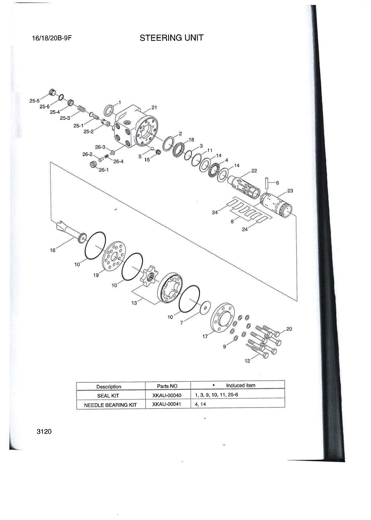
The valve and cylinder rebuild section. It opens with the 2-spool, 3-spool and 4-spool main control valve assemblies, then breaks each down into its block assemblies: MCV inlet section with main relief valve, MCV outlet section, MCV lift section (both without OPSS and with mast OPSS), MCV tilt section and MCV aux section. Each section is shown as a detailed exploded illustration with spools, poppets, springs, load check plugs, O-rings, wiper seals, solenoid valves and seal kits. The steering unit is covered with a full exploded view of the housing, drive shaft, rotor set, needle bearing kit and seal kit, and the tilt cylinder chapter shows the tube assembly, rod assembly, gland, piston, wear rings, O-rings, bushings and seal kit. The priority valve chapter completes the section with its plug, orifice, spool, housing, spring and name plate.
4. Power Train System
The drive unit section. It lists the left-hand and right-hand drive unit assemblies, then breaks them into housing sub-assemblies, cover-out sub-assemblies and parking sub-assemblies. The chapters give dowel pins, socket bolts, input pinions, ball bearings, retaining rings, air breathers, bleeding valves, brake plugs, magnetic plugs, gears, actuators, return springs, sun pinions, eccentric shafts, parking levers, quad rings and DU bushes, with separate lever bush kits for LH and RH. All fasteners are listed with their part numbers and quantities.
5. Steering & Control System
This chapter covers the steering column assembly, steering unit, steering cylinder, priority valve and brake system. The steering column, handle assembly, horn assembly and knob assembly are listed with their adjusters, shafts and levers. The brake section gives the brake pedal assembly, brake pedal weld, bracket weld, pedal pad, brake valve assembly, reservoir tank, hose, clamps and mounting hardware. Steering hydraulic piping is also covered here, with hose assemblies, elbows, connectors and clamps.
6. Structure
The chassis and operator station section. It covers the frame weld assembly (both non-SBR and SBR variants), shims, counterweight assemblies for the 16B-9F, 18B-9F and 20B-9F, counterweight bar, reflectors and cap bolts. The outer panel chapters list the dashboard weld assembly, dashboard covers, lower covers, rear column cover, front column cover, column support, battery cover weld, rear cover, floor plates, hinges, MCV cover, console box assembly, gas springs, weather strips and cushions. The overhead guard chapter includes head guard weld and sub-assemblies, LH and RH lamp brackets, rubber caps, grips, combination lamps, turn signal lamps, harnesses and grommets, plus back mirror, panorama mirror and bracket options. The battery stand chapter gives the stand weld, stoppers, rollers and shims, and the seat chapter covers both the standard Grammer mechanical suspension seat and the optional seat with air suspension, armrests, seat belts, heaters, lumbar support and side rails.
7. Attachment
The mast, carriage and cylinder section, covering the V-mast, VF-mast and TF-mast families. The outer mast chapters list mast weld assemblies for V250 through V550, TF370 through TF700 and the corresponding VF sizes, along with load roller bearings in standard, undersize, oversize and large sizes, shims, back-up liners, clamps, mast mounting pins, bronze bushings and grease nipples. The inner mast and middle mast chapters give mast weld assemblies, lift chains, chain wheel bearings, retaining rings, chain anchors, joint link kits, chain guards and chain wheels. The carriage and backrest chapters cover carriage weld assemblies, backrest weld assemblies, load roller bearings, bushings, back plates and socket bolts. The integral side shift chapters detail the side shift assembly with piping, hoses and connectors. Lift cylinder and free lift cylinder chapters are shown as exploded views with tube assemblies, rods, pistons, U-packings, wear rings, check valves, stop rings, cushion seals, dust wipers, rod bushes and seal kits for each mast size.
Numerical Part Index
A full numerical index of every part number in the manual, so you can start from a part number and find the illustration and parts table that contains it.
How This Hyundai Forklift Parts Manual Helps You
The Hyundai 16B-9F, 18B-9F and 20B-9F forklift truck parts manual is built for the real work of keeping a forklift running. When a hydraulic hose fails, when a mast chain stretches, when a contactor burns out or when a seat belt switch stops working, you need the exact part number, not a guess. This manual gives you the exploded view, the callout number, the part number and the quantity per machine for every component in the 16/18/20B-9F series. It also shows serial-number applicability, so you order the version that matches your truck, and interchangeability codes, so you know whether an old part can be replaced by a new one. The hydraulic valve and cylinder sections alone are worth the download – they break down each MCV section and lift cylinder into individual seals, springs, spools and poppets, with seal kit numbers that let you rebuild rather than replace.
Because the manual is a PDF, you can keep it on a laptop or tablet in the workshop, search the numerical index, and print the pages you need for the job. No shipping, no waiting – the file is available immediately after purchase.
IMAGES PREVIEW
Reviews
There are no reviews yet.