
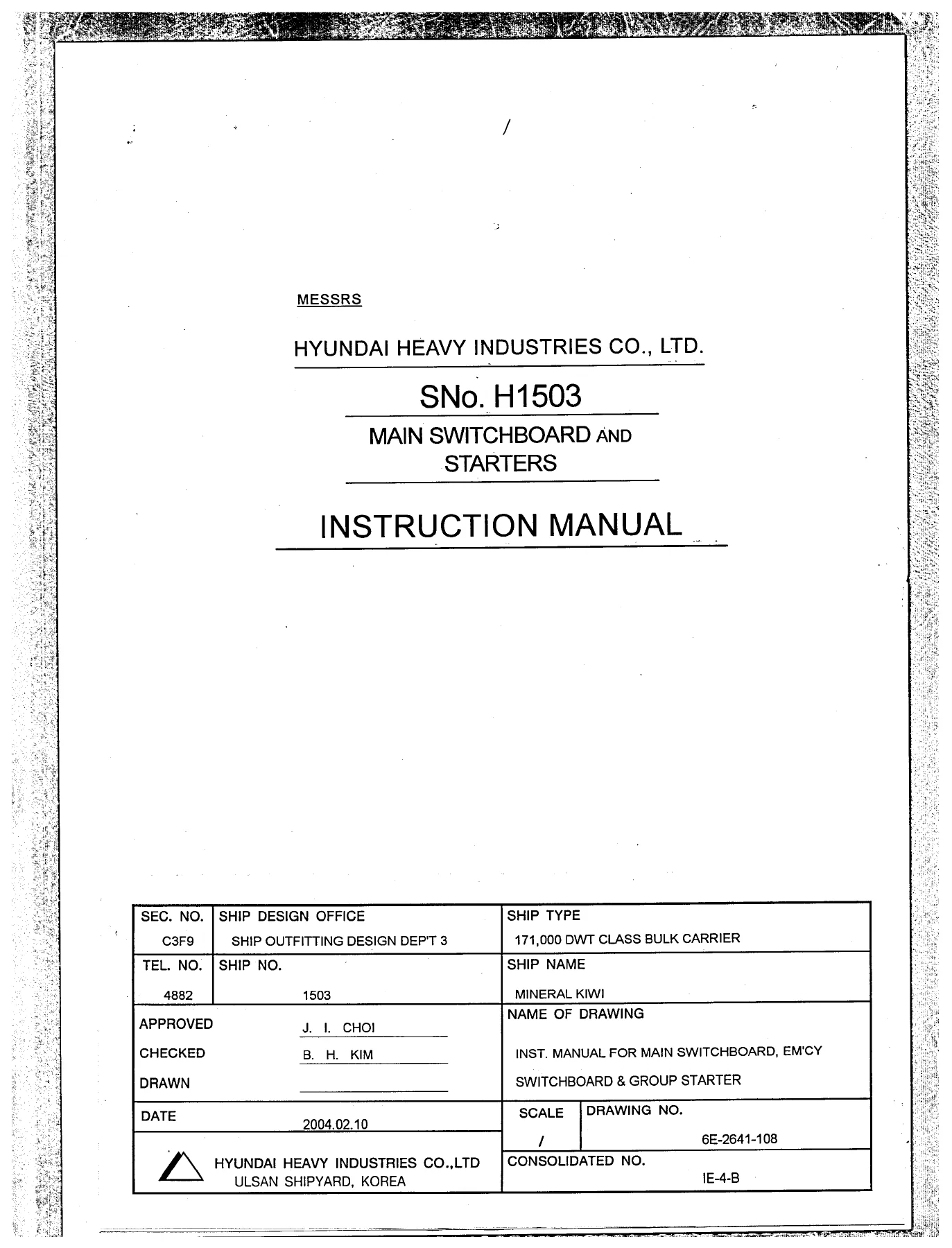
Hyundai Heavy Industries SMD H1503 Main Switchboard and Starters Instruction Manual
Original price was: $39.95.$23.95Current price is: $23.95.
Shipyard instruction manual for the Hyundai Heavy Industries SMD H1503 main switchboard, emergency switchboard and group starter installation on Ship No. H1503, including the ACONIS-PMS power management system, HiAN air circuit breakers, moulded case circuit breakers, protective relays and starter control documentation.
Description
Hyundai Heavy Industries SMD H1503 Main Switchboard and Starters Instruction Manual
Issued by Hyundai Heavy Industries Co., Ltd. from the Ulsan Shipyard, this Hyundai Heavy Industries SMD H1503 Main Switchboard and Starters Instruction Manual documents the complete electrical switchboard installation of Ship No. H1503, a 171,000 DWT class bulk carrier built to Nippon Kaiji Kyokai requirements. It is not a generic switchboard primer. It is the working instruction book for the main switchboard (MSB), the emergency switchboard (ESB) and the group starter assembly fitted to this vessel, and it carries the equipment-level documentation for every major device mounted inside those panels.
Three diesel generators rated AC 450 V, 3-phase, 60 Hz, 800 kVA feed the main switchboard, while a single emergency generator rated AC 450 V, 3-phase, 60 Hz, 162.5 kVA backs up the essential services through the emergency board. This manual shows how that distribution system is placed on the bus, paralleled, load-shared, monitored and protected.
File Details
- Manual type: Instruction manual
- Builder: Hyundai Heavy Industries Co., Ltd., Ulsan Shipyard, Korea
- Vessel: 171,000 DWT class bulk carrier, Ship No. H1503, Ship Name MINERAL KIWI
- Document title: Inst. Manual for Main Switchboard, Em’cy Switchboard and Group Starter
- Drawing No.: 6E-2641-108
- Consolidated No.: IE-4-B
- Date: 2004.02.10
- Language: English
- Page count: 489
- File format: PDF
Chapters Covered
- Introduction of switchboard
- Power Management System (ACONIS-PMS) — system description, control functions, card-level maintenance manual
- Air Circuit Breaker (HAT) — operation, draw-out mechanism, periodic inspection, parts replacement
- Moulded Case Circuit Breaker
- Reverse Power Relay (K2WR-R-S5)
- Voltage, Frequency and Auto Synchronizer Relay
- Insulation Resistance Monitor (SBAG-202)
- Group Annunciator System (SBGA type)
- Introduction of starters
- Motor Automatic Control System (HEEM-2)
- Replacement of FDC-connection MCCB with spare
- Magnetic contactors, thermal overload and control relays
- MSB construction, air circuit breakers and moulded case circuit breakers
- Starting and stopping of engine generator sets — manual start-stop control, manual generator control procedure, dead bus and live bus paralleling, stopping a generator
- Emergency generator operation in manual — initial check-out, engine start, voltage establishment, voltage and frequency check, feeding to loads, engine stop
- Automatic start-stop control of the emergency generator
- Shore connection and interlocking for the 440 V circuit
- Earth lamps, preference tripping system and trouble alarm signals
Read together, these chapters take a marine electrician from the physical layout of the dead-front switchboard through to the live procedures that put a generator on the bus. The MSB section explains the steel-angle framework, the 2.3 mm sheet-steel hinged panels, the laminated-phenolic insulation and the front and rear access arrangements for instrument transformers, relays and other internal devices. From there the manual moves into generator control: the conditions that must be satisfied before a diesel engine can be controlled from the switchboard, the voltmeter and frequency meter checks made phase-to-phase, the synchronising procedure using the synchroscope and synchro lamps, and the governor motor adjustments that divide kW load in proportion to generator capacity.
Generator Control, Synchronising and Load Management
The manual sets out the practical sequence for placing a generator onto a dead bus and onto a live bus. For a live bus, the incoming generator voltage must be almost equal to the bus voltage, its frequency equal to or slightly higher than bus frequency, and the generator circuit breaker must close at the exact instant the generator voltage is in phase with the bus. The behaviour of the synchroscope pointer is described in detail: rotation in the fast direction meaning generator frequency is high, slow rotation meaning it is low, a stationary pointer meaning frequencies match, and the 12 o’clock position marking synchronism with the two outer synchro lamps at equal brightness and the middle lamp dark.
Load division after closure, governor motor operation, and the correct order for stopping a generator — removing load, opening the ACB, then stopping the engine — are all covered. So is the automatic side of the same job: the AOR overcurrent trip device built into the generator ACB, with its long time delay, short time delay and preferential alarm sections, and the settings that trip the breaker on overload or short circuit.
ACONIS-PMS Power Management System
The ACONIS-PMS section describes the automated power management subsystem that controls up to four diesel generators on this installation. It covers the mimic board with its generator status, alarm and digital readouts, the mode select switches for synchronising, load sharing, load dependent start/stop and big motor blocking, and the main rack cards including the main and reserve MPM, COMM, IOSM, AIM16, DIM16, DOM16, PWRM and SLV modules.
Terminal-by-terminal input and output tables are given for the DIM16 and DOM16 boards, with the LED-by-LED meaning of each channel: ballast pump power requests, remote control possible signals, local/remote selector positions, ready-to-start signals, bus abnormal, stand-by selections, ACB closed status, black-out, short circuit and shutdown inputs. Automatic synchronising, load sharing and frequency control, load dependent start/stop thresholds, big motor blocking, stand-by selection and bus bar monitoring are each explained with their setting ranges.
Air Circuit Breakers, MCCBs and Protective Devices
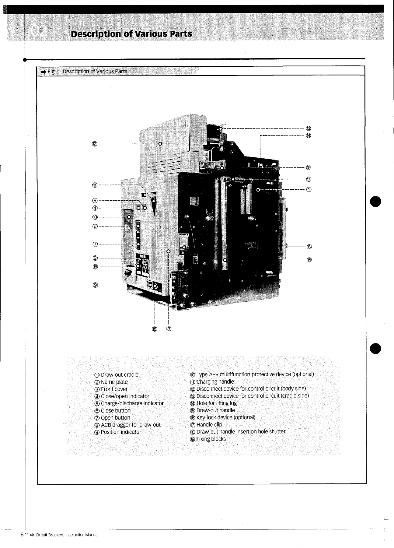
The HiAN series air circuit breaker instruction manual is reproduced in full: manual and motor charging types, spring charging, closing and opening operations, the draw-out mechanism with its CONN, TEST and ISOLATED positions, periodic inspection intervals, arc chamber and contact inspection, operating mechanism maintenance, and replacement of shunt trip devices, undervoltage trip devices, latch release coils, auxiliary switch units and motor control units.
The over-current protective device chapter covers the APR multifunction protective device in its APR-1L form for general feeder circuits and APR-1S form for generator protection, plus the APR-1D-GM type with its keypad menu structure. Base current selection, long time delay, short time delay, instantaneous, ground fault and pre-trip alarm settings are given with their pick-up and time ranges, along with field test methods, characteristic checks and the APR tester configuration.
The moulded case circuit breaker section covers the HBE economic series, HBS standard series, HBH high-fault level series, HBL extra high-fault level series, HBX current limiting series, HBD distribution and lighting breakers and the HSD moulded case switch, with time-current characteristic curves, ambient compensating curves, internally mounted accessory combinations and panel cut-out dimensions.
Starters, Contactors and Motor Control
Beyond the switchboard itself, the manual documents the group starter installation, the motor automatic control system (HEEM-2), the procedure for replacing an FDC-connection MCCB with a spare, and the maintenance precautions for magnetic contactors, thermal overload relays, control relays, fuses and current transformers. The safety chapters that open the book cover general handling precautions, hot-line work, fire extinguishing on electrical equipment, circuit breaker operation, and the prevention and treatment of electric shock.
What This Manual Lets You Do
With this Hyundai Heavy Industries SMD H1503 Main Switchboard and Starters Instruction Manual in hand, a marine electrician or engineer can perform generator start, stop, synchronising and load sharing from the main switchboard; operate the emergency switchboard and the emergency generator in both manual and automatic modes; restore essential services after a black-out; connect shore power through the 440 V shore connection and understand the interlocking that prevents a shore breaker and a generator ACB being closed at the same time; interpret the earth lamp indications on an earthed feeder system; and carry out periodic inspection of air circuit breakers, moulded case circuit breakers, contactors and relays.
Correct procedures and correct settings matter on a ship. Closing a generator breaker out of phase, mis-setting a preferential trip, or drawing out an ACB without releasing its closing spring all have consequences that this instruction manual is written to prevent. The switchboard is the point at which every generator, feeder and essential service on the vessel meets, and the manual treats it that way — with the actual operating sequences, setting ranges, alarm lists and inspection criteria used on board Ship No. H1503.
IMAGES PREVIEW
The document is supplied as an instant PDF download. There is no shipping and no waiting. Once ordered, the file is available immediately and can be read on a laptop, tablet or phone, or printed and kept in the engine control room or the electrical workshop where it will actually be used.
Reviews
There are no reviews yet.