Trusted Business
Verified & Licensed
Virus Free Files
100% Safe Downloads
Secure Payment
SSL Protected
Instant Delivery
Available Immediately
Hyundai HX10A Mini Excavator Operator’s Manual 2023 – PDF DOWNLOAD
$27.95
Instant PDF Download
Available immediately
Save to Your Device
Download & keep forever
Antivirus Scanned
100% virus-free
Trusted Worldwide
175,000+ customers
Description
Hyundai HX10A Mini Excavator Operator’s Manual 2023 – PDF DOWNLOAD
The Hyundai HX10A Mini Excavator Operator’s Manual 2023 (PDF) offers detailed instructions for safe and effective operation, including maintenance and safety guidelines, enhancing the user’s understanding and ensuring proper usage of the HX10A Mini Excavator.
FILE DETAILS:
Hyundai HX10A Mini Excavator Operator’s Manual 2023 – PDF DOWNLOAD
Language : English
Pages : 181
Downloadable : Yes
File Type : PDF
IMAGES PREVIEW OF THE MANUAL:
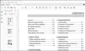
TABLE OF CONTENTS:
Hyundai HX10A Mini Excavator Operator’s Manual 2023 – PDF DOWNLOAD
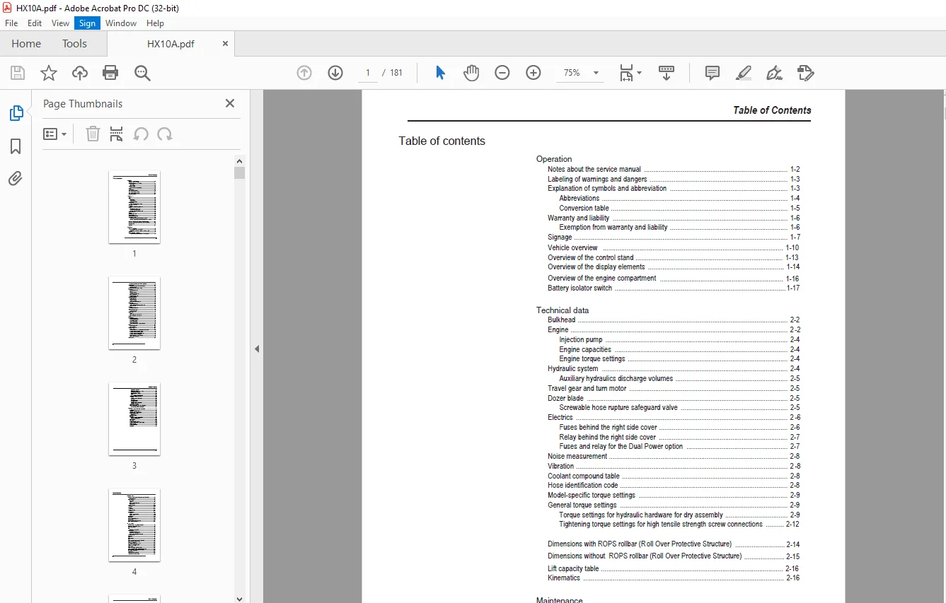
Operation
Notes about the service manual 1-2
Labeling of warnings and dangers 1-3
Explanation of symbols and abbreviation 1-3
Abbreviations 1-4
Conversion table 1-5
Warranty and liability 1-6
Exemption from warranty and liability 1-6
Signage 1-7
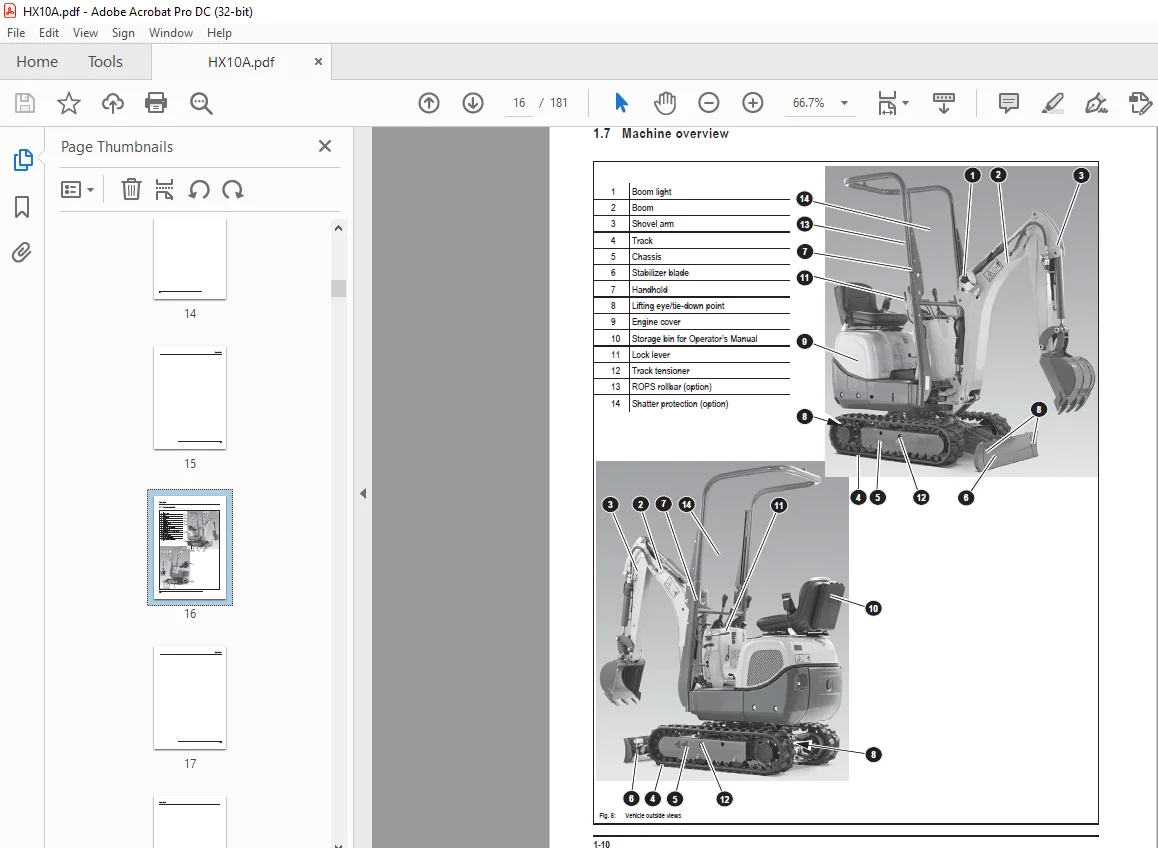
Vehicle overview 1-10
Overview of the control stand 1-13
Overview of the display elements 1-14
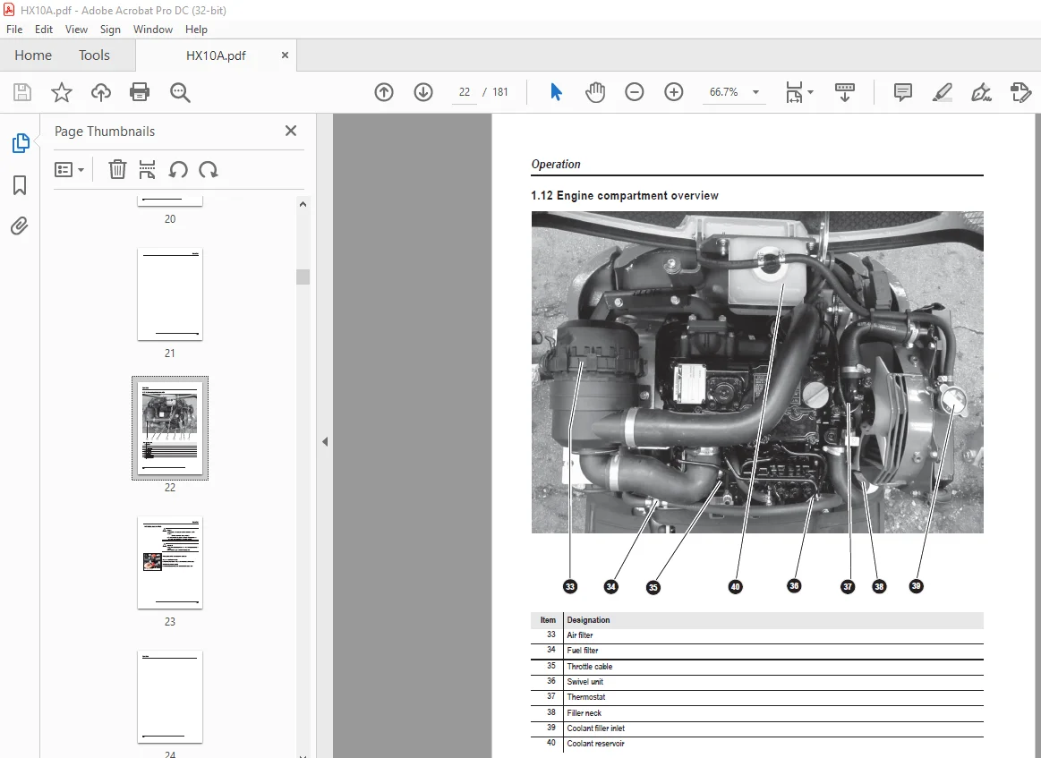
Overview of the engine compartment 1-16
Battery isolator switch 1-17
Technical data
Bulkhead 2-2
Engine 2-2
Injection pump 2-4
Engine capacities 2-4
Engine torque settings 2-4
Hydraulic system 2-4
Auxiliary hydraulics discharge volumes 2-5
Travel gear and turn motor 2-5
Dozer blade 2-5
Screwable hose rupture safeguard valve 2-5
Electrics 2-6
Fuses behind the right side cover 2-6
Relay behind the right side cover 2-7
Fuses and relay for the Dual Power option 2-7
Noise measurement 2-8
Vibration 2-8
Coolant compound table 2-8
Hose identification code 2-8
Model-specific torque settings 2-9
General torque settings 2-9
Torque settings for hydraulic hardware for dry assembly 2-9
Tightening torque settings for high tensile strength screw connections 2-12
Dimensions with ROPS rollbar (R oll Over Protective Structure) 2-14
Dimensions without ROPS rollbar (Roll Over Protective Structure) 2-15
Lift capacity table 2-16
Kinematics 2-16
Maintenance
Notes about maintenance 3-2
Responsibilities and previous conditions 3-2
Important safety instructions about care and maintenance jobs 3-2
Special tool 3-2
Engine/vehicle fluids and lubricants 3-3
Additional oil change and filter replacement of the hydraulics 3-4
Table of Contents
Table of Contents
I-2 SHB 803 en – Edition 2 7 * 803s20IVZ fm
Important notes about operation with bio-hydraulic oil 3-5
Maintenance label 3-6
Explanation of symbols on the maintenance label 3-6
Explanation of labels 3-8
Maintenance schedule (complete overview) 3-9
Fuel system 3-13
Special safety instructions 3-13
Refueling 3-13
Stationary fuel pumps 3-14
Specification of the diesel fuel 3-14
Bleed the fuel system 3-15
Fuel pre-filter with water trap 3-15
Change the fuel filter 3-17
Engine lubrication system 3-18
Check the oil level 3-18
Top off the motor oil 3-19
Change the motor oil 3-20
Replace the motor oil filter element 3-21
Cooling system 3-22
Special safety instructions 3-22
Checking the coolant level/topping off the coolant 3-23
Replace the coolant 3-25
Air cleaner 3-27
Replacing air filer element 3-28
V-belt 3-30
Check the V-belt tension 3-30
Re-tension the V-belt 3-31
Pressure check 3-32
General 3-32
Pressure check of the gear pump P2 3-32
Pressure check of the gear pump P1 3-33
Test log 3-34
Hydraulic system 3-36
Special safety instructions 3-36
Check the hydraulic oil level 3-37
Top off the hydraulic oil 3-38
Change the hydraulic oil 3-39
Replace the filter element 3-39
Check the hydraulic system and hydraulic hoses 3-40
Chains 3-41
Check the track tension 3-41
Setting the chains 3-42
Lubrication point overview 3-45
Park the vehicle 3-46
Lubrication points of the dozer blade and dozer blade cylinder 3-46
Lubrication points of the swiveling cylinder 3-47
Lubrication points of the swiveling cylinder 3-47
Lubrication points of the live ring bearing track 3-48
Lubrication points of the live ring teeth 3-49
Ball sockets (Option ISO/SAE switch-over) 3-50
Maintenance of attachments 3-50
Electrical system 3-51
Special safety instructions 3-51
Regular maintenance and service work 3-51
Notes about special elements 3-52
Three-phase current generator 3-52
Battery 3-53
Check the battery degasification hose 3-54
General care and maintenance work 3-55
Cleaning 3-55
General notes for all vehicle areas 3-55
Control stand 3-55
Entire vehicle exterior 3-56
Engine compartment 3-56
Screw connections and fastenings 3-56
Pivot points and hinges 3-56
Preparing for immobilization 3-57
Maintenance during long periods of immobilization 3-57
Commissioning after immobilization period 3-57
Engine
Overview of engine 3TNV70-VNS (TIER IV final) 4-2
Fuel system 4-3
Tapped clearance: Check and set 4-5
Tightening order of the cylinder head 4-6
Check the injection nozzles 4-7
Pressure check 4-7
Injection spray control 4-7
Injection time 4-8
Checking and setting the injection time 4-8
Replacing the injection pump 4-9
Setting the RPMs 4-10
Compression 4-10
Check the coolant thermostat 4-10
Check the thermal overload protection breaker 4-11
Oil pressure switch 4-11
Check the coolant circuit 4-12
Engine faults 4-13
Notes about the service manual 1-2
Labeling of warnings and dangers 1-3
Explanation of symbols and abbreviation 1-3
Abbreviations 1-4
Conversion table 1-5
Warranty and liability 1-6
Exemption from warranty and liability 1-6
Signage 1-7
Vehicle overview 1-10
Overview of the control stand 1-13
Overview of the display elements 1-14
Overview of the engine compartment 1-16
Battery isolator switch 1-17
Technical data
Bulkhead 2-2
Engine 2-2
Injection pump 2-4
Engine capacities 2-4
Engine torque settings 2-4
Hydraulic system 2-4
Auxiliary hydraulics discharge volumes 2-5
Travel gear and turn motor 2-5
Dozer blade 2-5
Screwable hose rupture safeguard valve 2-5
Electrics 2-6
Fuses behind the right side cover 2-6
Relay behind the right side cover 2-7
Fuses and relay for the Dual Power option 2-7
Noise measurement 2-8
Vibration 2-8
Coolant compound table 2-8
Hose identification code 2-8
Model-specific torque settings 2-9
General torque settings 2-9
Torque settings for hydraulic hardware for dry assembly 2-9
Tightening torque settings for high tensile strength screw connections 2-12
Dimensions with ROPS rollbar (R oll Over Protective Structure) 2-14
Dimensions without ROPS rollbar (Roll Over Protective Structure) 2-15
Lift capacity table 2-16
Kinematics 2-16
Maintenance
Notes about maintenance 3-2
Responsibilities and previous conditions 3-2
Important safety instructions about care and maintenance jobs 3-2
Special tool 3-2
Engine/vehicle fluids and lubricants 3-3
Additional oil change and filter replacement of the hydraulics 3-4
Table of Contents
Table of Contents
I-2 SHB 803 en – Edition 2 7 * 803s20IVZ fm
Important notes about operation with bio-hydraulic oil 3-5
Maintenance label 3-6
Explanation of symbols on the maintenance label 3-6
Explanation of labels 3-8
Maintenance schedule (complete overview) 3-9
Fuel system 3-13
Special safety instructions 3-13
Refueling 3-13
Stationary fuel pumps 3-14
Specification of the diesel fuel 3-14
Bleed the fuel system 3-15
Fuel pre-filter with water trap 3-15
Change the fuel filter 3-17
Engine lubrication system 3-18
Check the oil level 3-18
Top off the motor oil 3-19
Change the motor oil 3-20
Replace the motor oil filter element 3-21
Cooling system 3-22
Special safety instructions 3-22
Checking the coolant level/topping off the coolant 3-23
Replace the coolant 3-25
Air cleaner 3-27
Replacing air filer element 3-28
V-belt 3-30
Check the V-belt tension 3-30
Re-tension the V-belt 3-31
Pressure check 3-32
General 3-32
Pressure check of the gear pump P2 3-32
Pressure check of the gear pump P1 3-33
Test log 3-34
Hydraulic system 3-36
Special safety instructions 3-36
Check the hydraulic oil level 3-37
Top off the hydraulic oil 3-38
Change the hydraulic oil 3-39
Replace the filter element 3-39
Check the hydraulic system and hydraulic hoses 3-40
Chains 3-41
Check the track tension 3-41
Setting the chains 3-42
Lubrication point overview 3-45
Park the vehicle 3-46
Lubrication points of the dozer blade and dozer blade cylinder 3-46
Lubrication points of the swiveling cylinder 3-47
Lubrication points of the swiveling cylinder 3-47
Lubrication points of the live ring bearing track 3-48
Lubrication points of the live ring teeth 3-49
Ball sockets (Option ISO/SAE switch-over) 3-50
Maintenance of attachments 3-50
Electrical system 3-51
Special safety instructions 3-51
Regular maintenance and service work 3-51
Notes about special elements 3-52
Three-phase current generator 3-52
Battery 3-53
Check the battery degasification hose 3-54
General care and maintenance work 3-55
Cleaning 3-55
General notes for all vehicle areas 3-55
Control stand 3-55
Entire vehicle exterior 3-56
Engine compartment 3-56
Screw connections and fastenings 3-56
Pivot points and hinges 3-56
Preparing for immobilization 3-57
Maintenance during long periods of immobilization 3-57
Commissioning after immobilization period 3-57
Engine
Overview of engine 3TNV70-VNS (TIER IV final) 4-2
Fuel system 4-3
Tapped clearance: Check and set 4-5
Tightening order of the cylinder head 4-6
Check the injection nozzles 4-7
Pressure check 4-7
Injection spray control 4-7
Injection time 4-8
Checking and setting the injection time 4-8
Replacing the injection pump 4-9
Setting the RPMs 4-10
Compression 4-10
Check the coolant thermostat 4-10
Check the thermal overload protection breaker 4-11
Oil pressure switch 4-11
Check the coolant circuit 4-12
Engine faults 4-13
Hydraulics system
Gear pump PGP505B0040CA1H2NJ7J5C-505A0040XB1J5B1B1 5-2
Pump unit structure 5-3
Mobile valve block 5-6
Connections 5-6
Legend 5-7
Mobile valve block detailed plan 5 – 8
Pressure limits 5-9
Pump assignment 5-10
Drive 5-11
Function 5-12
Swivel unit 5-14
Swivel unit 5-15
Swivel implementation 5-16
Gaskets 5-16
Mechanical control 5-17
Joystick 5-17
Forward + reverse travel lever 5-18
Safety lock lever 5-19
Hydraulic faults 5-22
Plastic trims 5-22
Legend of the hydraulic diagram 5-24
Hydraulic diagram 5-25
Hydraulics diagram (Dual Power option) 5-27
Mobile valve block detailed plan 5-28
Electrical system
Ohmic law (current, voltage, resistance); Output 6-2
Measuring devices, measuring methods 6-2
Color coding of the lines 6-3
Relay 6-3
Application, mode of function 6-3
Electrical system 6-4
Fuses behind the right side cover 6-4
Relay behind the right side cover 6-5
Fuses and relay for the Dual Power option 6-5
Joystick touch button 6-6
Work lighting 6-6
Dynamo 6-7
Voltage regulator 6-7
Starter 6-7
Legend of the engine wiring harness (TIER IV final) 6-11
Engine wiring harness (TIER IV final) 6-11
Wiring harness displays 6-14
Cable supply for the operating hour meter 6-15
Wiring harness drive signal (option) 6-16
Wiring harness for horn 6-17
Battery cables 6-18
Wiring harness display (Dual Power option) 6-19
Legend engine/chassis wiring harness (Dual Power option) 6-20
Engine/chassis wiring harness (Dual Power option) 6-21
Seat console wiring harness 6-22
Wiring diagram 6-24
Wiring diagram Tier IV (Yanmar) 6-25
Wiring diagram (Dual Power option) 6-27
SHB 803 en – Edition 2 7 * 803s20IVZ fm I-5
ROPS (Roll Over Protective Structure) 7-2
Fold-down ROPS (Roll Over Protective Structure) 7-2
Fold ROPS (Roll Over Protective Structure): 7-2
Tilt ROPS (Roll Over Protective Structure): 7-3
Fold-down (Roll Over Protective Structure) : 7-3
Fold ROPS (Roll Over Protective Structure): 7-4
ISO/SAE switch-over (option) 7-6
Driving signal (option) 7-7
Telematics 7-8
Connections 7-8
Functional check/luminous diode 7-8
Zero emission Dual Power drive system 7-9
Overview 7-9
Customer Support: [email protected]
S.V 02/24