Hyundai HX300AL Crawler Excavator Service Repair Manual – PDF Download
$59.95 Original price was: $59.95.$29.95Current price is: $29.95.
Hyundai HX300AL Crawler Excavator Service Repair Manual
Description
Hyundai HX300AL Crawler Excavator Service Repair Manual
Service Manual Covers:
Hyundai HX300AL Crawler Excavator Service Repair Manual
- Foreword
- Structure
- How To Read The Service Manual
- Conversion Table
- General
- Safety
- Specifications
- Major Component
- Specifications
- Working Range
- Weight
- Lifting Capacities
- Bucket Selection Guide
- Under Carriage
- Specifications For Major Components
- Recommended Oils
- Structure And Function
- Pump Device
- Structure
- Function
- Main Control Valve
- Structure
- Hydraulic Circuit
- Function
- Control In Neutral Position
- Travel Operation
- Boom Operation
- Holding Valve Operation
- Bucket Operation
- Swing Operation
- ARM Operation
- Operation Of Swing Priority Spool
- Operation Of Option Spool
- Operation Of Negative Control Valve
- Operation Of Main Relief Valve
- Operation Of Port Relief Valve
- Swing Device
- Structure
- Principle Of Driving
- Travel Device (Type 1&2)
- Construction
- Specification
- Operation
- Travel Device (Type 3, High Walker)
- Construction
- FUNCTION
- RCV Lever
- Structure
- Functions
- RCV Pedal
- Structure
- Cross Section
- Function
- Hydraulic System
- Main Circuit
- Pilot Circuit
- Single Operation
- Combined Operation
- Electrical System
- Component Location
- Location 1
- Location 2
- Electrical Circuit
- Power Circuit
- Starting Circuit
- Charging Circuit
- Head And Work Light Circuit
- Beacon Lamp And Cab Light Circuit
- Wiper And Washer Circuit
- Controller Circuit
- Monitoring Circuit
- Electrical Component Specification
- Connectors
- Connector Destination
- Connection Table For Connectors
- Connectors 1
- Connectors 2
- Mechatronics System
- Outline
- Mode Selection System
- Power Mode Selection System
- Work Mode Selection System
- User Mode Selection System
- Automatic Deceleration System
- Power Boost System
- Travel Speed Control System
- Automatic Warming Up System
- Engine Overheat Prevention System
- Variable Power Control System
- Attachment Flow Control System
- Boom Floating Control System
- Intelligent Power Control System
- Anti-Restart System
- Self-Diagnostic System
- Outline
- Monitoring
- Machine Error Codes Table
- Engine Fault Code
- Engine Control System
- EPPR Valve
- Pump Eppr Valve
- Boom Priority Eppr Valve
- Monitoring System
- Outline
- Cluster
- Monitor Panel
- Cluster Check Procedure
- Cluster Connector
- Gauge
- Warning Lamps
- Pilot Lamps
- Switches
- Main Menu
- Air Conditioner And Heater
- Fuel Warmer System
- Troubleshooting
- Before Troubleshooting
- Introduction
- Diagnosing Procedure
- Hydraulic And Mechanical System
- Introduction
- Drive System
- Hydraulic System
- Swing System
- Travel System
- Attachment System
- Electrical System
- When Starting Switch Is Turned On, Cluster Display Does Not Appear
- Communication Error Flashes On The Cluster (Hcespn 840, Fmi)
- Battery Charging Warning Lamp Lights Up (Starting Switch : On)
- When Coolant Overheat Warning Lamp Lights Up (Engine Is Started)
- When Air Cleaner Warning Lamp Lights Up (Engine Is Started)
- When Engine Oil Pressure Warning Lamp Lights Up (Engine Is Started)
- When Hydraulic Oil Temperature Warning Lamp Lights Up (Engine Is Started)
- Whe Re Gauge Does Not Operate
- When Fuel Gauge Does Not Operate (Hcespn 301, Fmi 3 Or 4)
- When Safety Solenoid Does Not Operate
- When Travel Speed 1, 2 Does Not Operate (Hcespn 167, Fmi 4 Or 6)
- When Engine Does Not Start (Lights Up Condition)
- When Starting Switch On Does Not Operate
- When Starting Switch Is Turned On, Wiper Motor Does Not Operate
- When Starting Switch Is Turned On, Head Lamp Does Not Lights Up
- When Starting Switch Is Turned On, Work Lamp Does Not Lights Up
- Mechatronics System
- All Actuators Speed Are Slow
- Engine Stall
- Malfunction Of Cluster Or Mode Selection System
- Auto Decel System Does Not Work
- Malfunction Of Pump 1 Pressure Sensor
- Malfunction Of Pump 2 Pressure Sensor
- Malfunction Of Pump 3 Pressure Sensor
- Malfunction Of Negative 1 Pressure Sensor
- Malfunction Of Negative 2 Pressure Sensor
- Malfunction Of Swing Pressure Sensor
- Malfunction Of Bucket In Pressure Sensor
- Malfunction Of Boom Up Pressure Sensor
- Malfunction Of Boom Down Pressure Sensor
- Malfunction Of Power Max
- Malfunction Of Boom Priority EPPR Valve
- Malfunction Of Arm Regeneration Solenoid
- Maintenance Standard
- Operational Performance Test
- Purpose
- Terminology
- Operation For Performance Tests
- Observe The Following Rules In Order To Carry Out Performance Tests Accurately And Safely
- Engine Speed
- Travel Speed
- Track Revolution Speed
- Travel Deviation
- Swing Speed
- Swing Function Drift Check
- Swing Bearing Play
- Hydraulic Cylinder Cycle Time
- Dig Function Drift Check
- Control Lever Operating Force
- Control Lever Stroke
- Pilot Primary Pressure
- For Travel Speed Selecting Pressure:
- Swing Parking Brake Releasing Pressure
- Main Pump Delivery Pressure
- System Pressure Regulator Relief Setting
- Major Component
- Main Pump
- Main Control Valve
- SWING DEVICE
- Travel Motor
- RCV Lever
- RCV Pedal
- Turning Joint
- Cylinder
- Track And Work Equipment
- Track
- Work Equipment
- Disassembly And Assembly
- Precautions
- Tightening Torque
- Pump Device
- Removal And Install
- Main Pump (1/2)
- Structure
- Tools And Tightening Torque
- Disassembly
- Assembly
- Regulator
- Structure (1/2)
- Regulator (2/2)
- Tools And Tightening Torque
- Disassembly
- Assembly
- Main Control Valve
- Removal And Install Of Motor
- Structure
- Disassembly And Assembly
- General Precautions and Tools
- Disassembly
- Swing Device
- Removal And Install Of Motor
- Disassembly And Assembly Of Swing Motor
- Structure
- Disassembly
- Assembling
- Disassembly And Assembly Of Reduction Gear
- Structure
- Disassembly Reduction Gear
- Assembly Reduction Gear
- Travel Device (Type1&2)
- Removal And Install
- Travel Motor
- Disassembling Travel Motor
- Reassembling Travel Motor
- Reduction Gear
- Disassembling Reduction Gear
- Assembly Redution Unit
- Travel Motor (Type 3, High Walker)
- Removal And Install
- Travel Motor
- Travel Reduction Gear
- Disassembling
- Assembling
- RCV Lever
- Removal And Install
- Disassembly And Assembly
- Guide
- Disassembly
- Assembly
- Turning Joint
- Removal And Install
- Disassembly And Assembly
- Structure
- Disassembly
- Assembly
- Boom, Arm And Bucket Cylinder
- Removal And Install
- Disassembly And Assembly
- Structure-Bucket cylinder
- Structure-Arm cylinder
- Structure-Boom cylinder
- Structure-Adjustment cylinder
- Tools And Tightening Torque
- Disassembly
- Assembly
- Undercarriage
- Track Link
- Carrier Roller
- Track Roller
- Idler And Recoil Spring
- Removal and Install
- Disassembly and Assembly of Idler
- Disassembly and Assembly of Recoil Spring
- Work Equipment
- Structure
- Removal And Install
- Attached Circuit Diagrams
- Hydraulic Circuit
- Electrical Circuit (1/3)
- Electrical Circuit (2/3)
- Electrical Circuit (3/3)
- Electrical Circuit For Hydraulic (1/2)
- Electrical Circuit For Hydraulic (2/2)
HYUNDAI HX300AL CRAWLER EXCAVATOR SERVICE REPAIR MANUAL – PDF DOWNLOAD:
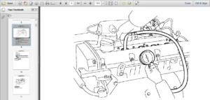
Image of the Manual:
Manual Covers:
Hyundai HX300AL Crawler Excavator Service Repair Manual
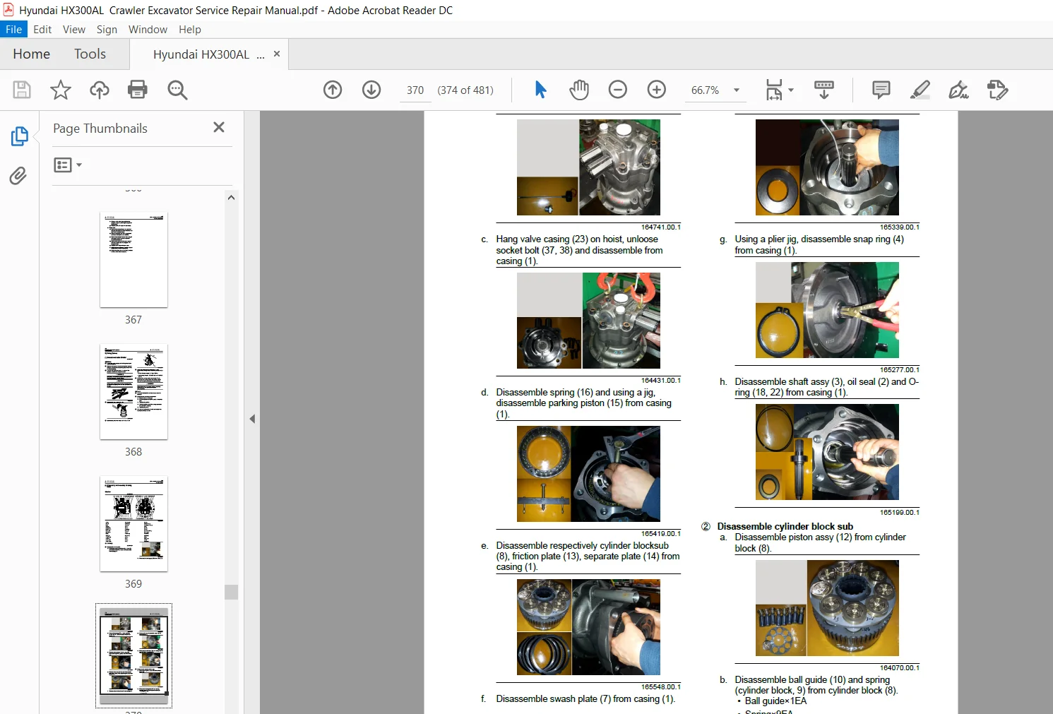
This service manual has been prepared as an aid to improve the quality of repairs by giving the serviceman an accurate understanding of the product and by showing him the correct way to perform repairs and make judgments. Make sure you understand the contents of this manual and use it to full effect at every opportunity.
This service manual mainly contains the necessary technical information for operations performed in a service workshop.
For ease of understanding, the manual is divided into the following sections.
SECTION 1 GENERAL
This section explains the hints and gives the specification of the machine and major components.
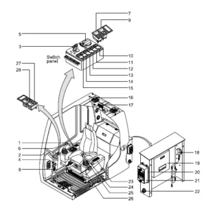
SECTION 2 STRUCTURE AND FUNCTION
This section explains the structure and function of each component. It serves not only to give an understanding of the structure, but also serves as reference material for troubleshooting.
SECTION 3 HYDRAULIC SYSTEM
This section explains the hydraulic circuit, single and combined operation.
SECTION 4 ELECTRICAL SYSTEM
This section explains the electrical circuit, monitoring system and each component. It serves not only to give
an understanding electrical system, but also serves as reference material for trouble shooting.
SECTION 5 MECHATRONICS SYSTEM
This section explains the computer aided power optimization system and each component.
SECTION 6 TROUBLESHOOTING
This section explains the troubleshooting charts correlating problems to causes.
SECTION 7 MAINTENACE STANDARD
This section gives the judgment standards when inspecting disassembled parts.
SECTION 8 DISASSEMBLY AND ASSEMBLY
This section explains the order to be followed when removing, installing, disassembling or assembling each component, as well as precautions to be taken for these operations.
This specifications contained in this shop manual are subject to change at any time and without any advance notice. Contact your HYUNDAI distributor for the latest information.
Please Note:
β¦ This is the SAME manual used by the dealers to troubleshoot any faults in your vehicle. This can be yours in 2 minutes after the payment is made.
β¦ Contact us at [email protected] should you have any queries before your purchase or that you need any other service / repair / parts operators manual.
2 reviews for Hyundai HX300AL Crawler Excavator Service Repair Manual – PDF Download
What Our Customers Say
π Related Products
Discover more professional manuals for your equipment

2006 Hyundai sonata Service Repair Manual - DOWNLOAD

Hyundai Robex 160lc 7 Crawler Excavator Service Repair Workshop Manual Download

2006 Hyundai Tucson Service Repair Manual - DOWNLOAD


Cohen Zev –
Alfred Mordechai –
To download the manuals is no problem but to open them or to find a app to open it is difficult