Hyundai HX300LL Excavator Shop Manual 2023 – PDF DOWNLOAD
$36.95
Description
Hyundai HX300LL Excavator Shop Manual 2023 – PDF DOWNLOAD
The Hyundai HX300LL Excavator Shop Manual 2023 is a comprehensive PDF guide for maintenance and repairs. It facilitates efficient servicing of the specified excavator model with updated information for the year 2023.
FILE DETAILS:
Hyundai HX300LL Excavator Shop Manual 2023 – PDF DOWNLOAD
Language : English
Pages : 1206
Downloadable : Yes
File Type : PDF
IMAGES PREVIEW OF THE MANUAL:
TABLE OF CONTENTS:
Hyundai HX300LL Excavator Shop Manual 2023 – PDF DOWNLOAD
HX300LL 0
Revision 0
Table of Contents 1
Safety 3
Forestry Machine Maintenance Safety 5
Safety Instructions 9
Safety Messages 9
General 10
Safe Operation is Operator’s Responsibility 10
Know Your Machine 10
Proper Work Tools and Attachments 11
Pressurized Fluids 11
Flying or Falling Objects 12
Personal Protective Equipment (PPE) 13
Correction of Machine Problems 13
Crushing and Cutting 13
Hot Coolant and Oils – Burn Prevention 14
Fire and Explosion Prevention 15
Fire Extinguisher and First-aid Kit (Emergency Medical Kit) 18
Electrical System and Electrical Shock 19
Operator Protective Guards and Structures (Optional) 19
Transportation 20
Obey State and Local Over-the-Road Regulations 20
Loading and Unloading 20
Transporting Machine 21
Operation 22
Before Engine Starting 22
Work Site 23
Mounting/Dismounting 24
Cleaning 25
Operator Station 25
Seat Belt 26
Visibility Information 27
Boost Starting or Charging Engine Batteries 28
Starting Engine 29
Swinging or Traveling 30
Lifting and Logging 32
Operation on Slopes 33
Towing 34
Attachment 35
Equipment Lowering with Engine Stopped 35
Engine Stop 36
Parking Machine 36
Preservation/Storing Machine 37
Maintenance 39
Warning Tag 41
Cleaning 42
Proper Tools and Clothing 42
Disassembling Precautions 42
Use of Lighting 42
Fire and Explosion Prevention 43
Burn Prevention 44
Rubber That Contains Fluorides 45
Rubber and Plastics 46
Welding Repairs 47
Warning for Counterweight and Front Attachment Removal 48
Lock Inspection Covers 49
Working on Machine 49
Accumulator 50
Compressed Air 50
Track Tension Adjustments 51
Supports and Blocking for Work Equipment 51
High-pressure Lines, Tubes and Hoses 52
Battery 53
Environment and Circumstances 55
Work Site Areas Requiring Extra Caution 55
High-voltage Cables 57
Underground Operation 58
Working in Water 58
Working in Contaminated Environment 58
Operation in Extreme Conditions 59
Exhaust Ventilation 63
Asbestos Information 64
Silica Dust Information 64
Disposal of Hazardous Materials 65
Specifications 67
Specifications 69
Safety Instructions 72
General Description 72
• The Upper Structure 72
• The Lower Undercarriage and Track Frames 72
• The Forestry Machine Front-end Attachment 72
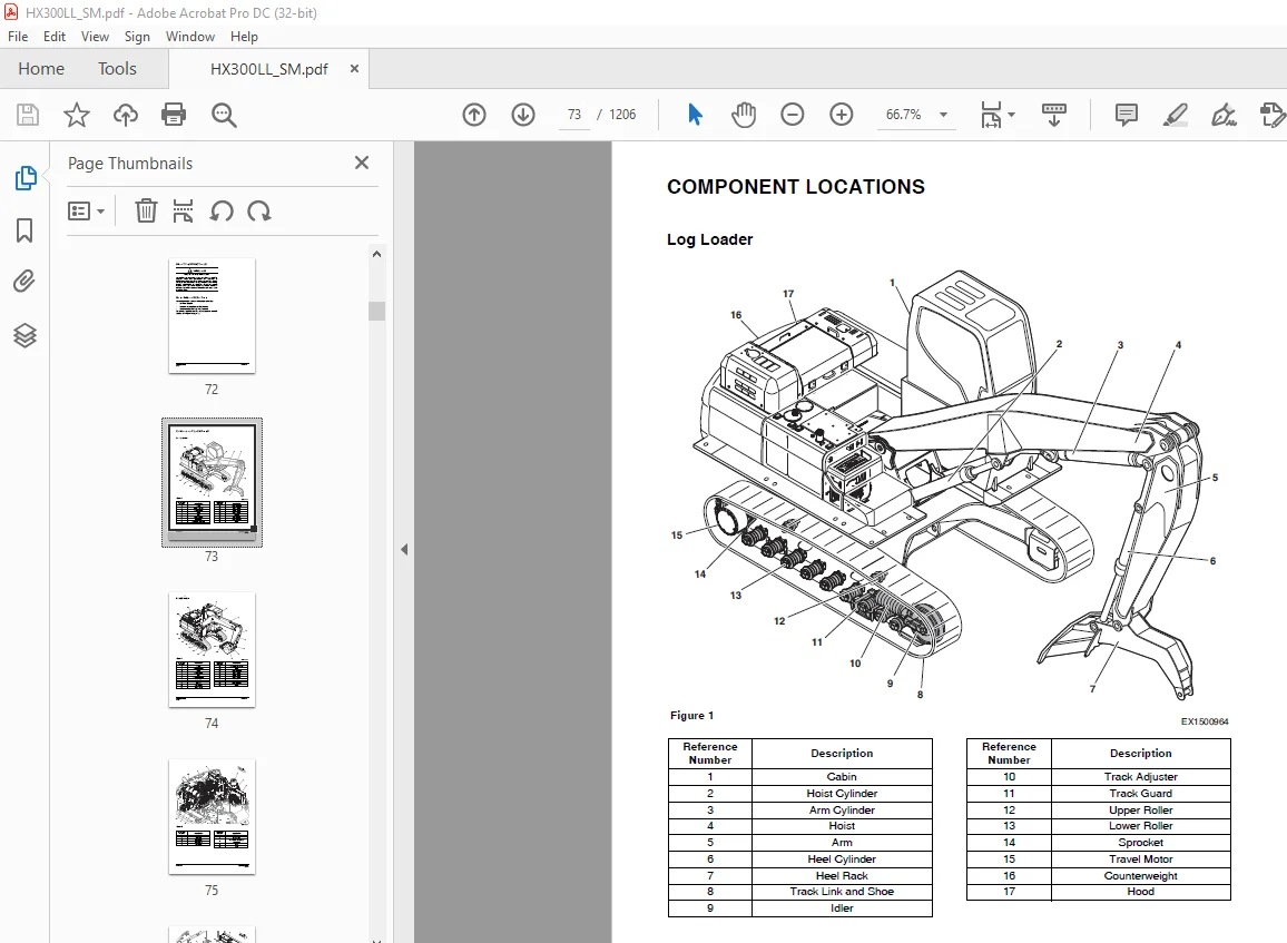
Component Locations 73
Log Loader 73
Road Builder 74
General Dimensions 78
Log Loader 78
Road Builder 80
General Specifications 0
• Boom: LL 6,300 mm, RB 6,245 mm 0
• Arm: LL 3,912 mm, RB 3,100 mm 0
• Heel: 990 mm 0
• Bucket (SAE): H Class 1 60 m3 0
• Shoe: STD 700 mm (DG), OPT 700 mm (TG), 800 mm (DG) 0
• Grapple: STD TC-52, OPT (TC-58, TC-66, RHLG-52, RHLG-64, RHLG-72) 0
• STD: LL Boom (6,300 mm), LL Arm (3,912 mm), Heel (990 mm), Non Rops CAB, 700 mm (DG) Shoe 0
• OPT 1: LL Boom (6,300 mm), LL Arm (3,912 mm), Heel (990 mm), Oregon CAB, 700 mm (DG) Shoe 0
• OPT 2: RB Boom (6,245 mm), RB Arm (3,100 mm), H Class Bucket (1 60 m3), Oregon CAB, 700 mm (DG) shoe 0
• OPT 3: RB Boom (6,245 mm), RB Arm (3,100 mm), H Class Bucket (1 60 m3), Rops CAB, 700 mm (DG) Shoe 0
Approximate Weight of Workload Materials 82
Performance Tests 84
Purpose of Performance Tests 84
1 To comprehensively evaluate each operational function by comparing the performance test data with the standard values 84
2 According to the evaluation results, repair, adjust, or replace parts or components as necessary to restore the machine’s performance to the desired standard 84
3 To economically operate the machine under optimal conditions 84
Kinds of Tests 84
1 Base machine performance test is to check the operational performance of each system such as engine, travel, swing, and hydraulic cylinders 84
2 Hydraulic component unit test is to check the operational performance of each component such as hydraulic pump, motor, and various kinds of valves 84
Performance Standards 84
Precautions for Evaluation of Test Data 84
Definition of “Performance Standard” 84
Preparation for Performance Tests 85
The Machine 85
Test Area 85
Precautions 85
Make Precise Measurement 85
Operational Performance Standard Table 86
• Standard Condition: P Plus Mode, SPC On, Engine Dial Max Auto Idle Off, Air Conditioner Off, Digging Mode, Oil 50 ±10°C, Coolant 80 +10°C 87
Operational Performance Test 88
Hydraulic Cylinder Cycle Time 88
Travel Speed 90
Track Revolution Speed 91
Mistrack Check 93
Swing Speed 95
Swing Function Drift Check 96
Cylinder Creep 97
General Maintenance 99
General Maintenance Instructions 101
Safety Instructions 105
Welding Precautions and Instructions 106
Hydraulic System – General Precautions 107
Maintenance Service and Repair Procedure 109
General Precautions 109
Hydraulic System Cleanliness and Oil Leaks 110
Maintenance Precautions for Hydraulic System Service 110
• Use a noncombustible, evaporative type, low residue solvent and thoroughly clean exterior surfaces of assemblies before any part of the circuit is opened or disassembled 110
• Keep dismantled parts covered during disassembly Use clean caps, plugs or tape to protect the disconnected openings of flanges, manifolds and piping 110
• Do not allow cleaning solvents or other fluids to mix with the oil in the system Use clean oil to flush any traces of solvent or other residue before reassembly 110
• If metal or rubber fragments are found in the system, flush and replace all fluid in the system and troubleshoot the circuit to identify the source of contamination 110
Oil Leakage Precautions 111
Cleaning and Inspection 112
General Instructions 112
Bearing Inspection 113
Standard Torques 121
Safety Instructions 125
Torque Values for Standard Metric Fasteners 126
Torque Values for Standard U S Fasteners 127
Type 8 Phosphate Coated Hardware 129
Torque Values for Hose Clamps 130
ORFS Swivel Nut Recommended Torque 130
Torque Values for Split Flanges 131
Torque Wrench Extension Tools 132
• Recommended torque exceeds the measuring capacity of the torque wrench 132
• Specialized sockets do not fit the adapter on the front end (nose) of the torque wrench 132
• Generating adequate force on the back end (handle) of the wrench is difficult or impossible 132
• Restricted access or an obstruction may make use of the torque wrench impossible 132
• A unique application requires fabrication of an adapter or other special extension 132
Torque Multiplication 132
• If the extension itself absorbs some of the tightening force and starts to bend or bow out 133
• If an extension has to be fabricated that is not perfectly straight (for example, an extension made to go around an obstruction, to allow access to a difficult to tighten fastener), the materials and methods used must be solid enough to transmit 133
Other Uses for Torque Wrench Extension Tools 133
Tightening Torque Specifications (Metric) 134
Engine 137
Engine 139
Overview 143
General Information 144
General Description 144
Engine Maintenance 148
Inspection and Repair of the Engine 151
Engine Identification 153
Engine Data Plate 153
Engine Specification 155
Engine Performance Curves 156
Special Tools 157
Tightening Torques 161
Major Parts Tightening Torque 161
• A tolerance of ±15 % applies to all values unless otherwise specified 161
• All contact surfaces are to be clean and free of paint 161
• Bolts and nuts are normally not lubricated regardless of surface treatment All exceptions are specified in the inspection information 161
Tightening Torque for General Bolts 163
Tightening Torque of Plug Screw 164
Hollow Screw (4-Hole) Tightening Torque 164
Engine Disassembly 165
Engine Disassembly Procedure 165
• Prepare the necessary tools and genuine parts before engine disassembly 165
• Prepare a shelf to keep removed parts 165
• Keep the working area well lighted and clean 165
• Keep your hands clean at all times during service 165
• Keep parts removed from the engine in the removal order 165
• Make sure that removed parts are not mixed and do not touch each other 165
• Never open the radiator cap while the engine is hot If opening the radiator cap while the engine is still hot, hot coolant may spurt, resulting in a severe burn Open the radiator cap after confirming that the engine is After draining coolant, i 165
• Put a label on the coolant container not to get mixed with other containers If you swallow coolant, seek professional medical help immediately 165
• Seal the common rail thoroughly after removing it to prevent foreign materials from entering it 168
• Once the fuel high-pressure pipe is disconnected, it cannot be reused 168
• Make sure that the main bearing and bearing caps are not mixed 178
• Fit the main bearings to their bearing caps temporarily to prevent mixing 178
Engine Assembly 180
Engine Assembly Sequence 180
• Clean all the removed parts thoroughly Especially, clean the oil and coolant passages with compressed air thoroughly to eliminate any restriction 180
• Organize general tools and special service tools for engine assembly 180
• Prepare clean engine oil to apply onto moving parts 180
• Prepare service parts, such as sealant and gasket 180
• Replace any used gasket, seal ring and consu ables with new ones 180
• Each bolt should to tightened to the specified torque according to the tightening order Never over-tighten it 180
• After installing the engine components, check their proper operation 180
• After primary assembly, check if any bolt is loose 180
• Keep your hands clean at all times during work 180
• Make sure that the temperature of the ring gear does not exceed 200°C 185
• When installing the wear ring, heat it to 150°C with a heater, and apply loctite #262 to it, and use an assembly jig to install it 185
• Be careful not to damage the gasket 191
• If the pin hole cannot be aligned, lift the head and then try to seat it again 191
• Clean all parts thoroughly and make sure that no foreign material enters any part 193
• Especially, the fuel line between the common rail and injector is not equipped with a filtering function Therefore, this section should be kept clean with care 193
• Clean the drilling of the head for the fuel high- pressure connector and the hole for the injector thoroughly to remove any foreign materials from them 193
• If the injector is removed, the fuel high-pressure connector should be replaced with a new one 193
• If fuel collected in the fuel return line enters the combustion chamber during injector disassembly process, remove fuel by sucking it out with a hand pump or by cranking the engine with fuel flow blocked 193
• Never reuse the fuel high-pressure pipe 198
• Tighten the fuel high-pressure pipe to the specified torque for a cylinder by cylinder 198
Cylinder 203
General Information 203
Cylinder Head 203
Cylinder Head Inspection 207
Bottom Distortion 207
Flatness 207
Cylinder Block 208
Valve Mechanism 210
Valve 211
Rocker Arm 212
Valve Tappet and Push Rod 213
Valve Stem O D 213
Valve Seat Contact Surface 214
Valve Head Thickness 214
Contact area on contact surface 214
• Check if there is any foreign material in the oil feed hole of the rocker arm shaft Wash it cleanly 217
• Make sure to install the rocker arm in the correct position in the correct order 217
Visual Inspection 217
Rocker Arm Bushing I D 217
Deflection of Rocker Arm Shaft 218
Rocker Arm Shaft O D 218
Tappet Clearance 218
Visual Inspection of Tappet 218
Tappet O D 219
• When disassembling the engine or cylinder head, 220
• When loud noise is heard from the valve connection, 220
• When the fuel injection system is intact but the engine operates abnormally 220
Method 1 221
Method 2 221
Actuating System 222
Camshaft 222
Measure the height of the cam lobe 223
Check the cam surface 223
Clearance between camshaft and bearing 223
Camshaft deflection 223
Piston 224
• The piston is an important component that receives higher combustion pressure, So it is necessary to scrap it if the head or pin hole part involves even a tiny scratch 224
• Sometimes, the assembly can be done upside down since the shapes of the top and bottom side are similar So, the assembly work requires attention 224
• If the assembly is complete upside down, the piston may run abnormally, which leads to higher consumption of oil, increase of bypass gas, damage to the ring, and sometimes even stand burn of the engine Therefore, the whole assembly process needs 224
Visual inspection 225
Clearance between piston and cylinder liner 225
Visual Inspection 226
Piston Ring Gap 226
Piston Ring Side Clearance 226
Piston Ring Tension 227
Connecting Rod 228
Distortion 229
Hole Parallelization 229
Wear 229
Crankshaft 230
Inspection for Defect 231
Wear Measurement 231
Crankshaft Deflection 232
Visual Inspection 232
Oil clearance between crankshaft and bearing (method 1: using dial gauge): 232
Oil Clearance between Crankshaft and Bearing (Method 2: Using Plastigauge): 233
Bearing Spread and Crush 234
Timing Gear 236
Lubrication system 237
General Information 237
Oil Pan 241
Oil Pump 243
Oil Filter 245
• When replacing the cartridge of the oil filter, make sure to use the specified genuine one 246
• The oil filter should be installed to the engine without oil in it Never fill the new oil filter with oil drained from the used oil filter 246
Exhaust System 248
Turbocharger 248
Cautions for Engine Operation 256
Cautions for Maintenance 257
Daily Inspection and Service 258
Periodic Inspection and Service 259
EGR (Exhaust Gas Recirculation) System 261
Flow of Air and Exhaust Gases 262
Controlling the Flow 262
Cold Engine 263
Warm Engine 263
Shut-off Conditions 263
• The control unit shuts down the EGR system if: 263
• The charge air temperature falls below a specific value There is then a risk of freezing in the intake manifold 263
• The engine is at such a high altitude that air pressure affects its performance 263
• Coolant temperature is too high At very high coolant temperature, the control unit closes the EGR valve to avoid loading the engine with additional heat from the EGR cooler 263
• The white smoke limiter is active 263
• There is a risk of the EGR system freezing if the ambient temperature is very low 263
Disassembly 266
Assembly 266
DNOx System 268
Dosing Module 276
Supply Module 276
Urea Tank 277
Muffler and Other Pipes 278
Cooling System 279
General information 279
Thermostat 280
• The wax pellet type thermostat shows slower response to the change of cooling water than the bellows type thermostat This happens because the heat capacity of the wax pellet type thermostat is larger than that of the bellows type thermostat The 280
• When draining water from the engine cooler or injecting water to the engine cooler, work slowly to ensure that all air inside the cooler is expelled 280
• When a defect is found in the thermostat, replace it with a new one 280
Fuel System 284
General Information 284
Fuel High-pressure System Components 286
Injector 287
Common Rail 291
Fuel Injection Pump 296
Function 296
Structure Fuel High-pressure Pump 297
Operation 297
Fuel Return 297
Fuel High-pressure Pumping Cut-off Valve 297
Electrical System 299
Electrical Parts 299
Switches and Sensors 301
ECU (Electronic Control Unit) 306
Engine Start 307
Vehicle Driving 307
Driver-requested Adjustment of rpm 307
Limp Home 307
Failure Diagnosis 307
Driving Record 308
Starter 308
Engine Harness 310
ECU Circuit 0
Engine Coolant Heater (Option) 319
Disassembly and Assembly 323
Changing the Circulating Pump 323
1 Remove heater 323
Changing the Temperature Limiter 325
Changing the Temperature Sensor 326
Changing the Combustion Air Fan 328
Changing the Burner, Flame Monitor and Glow Plug 330
Changing the Burner Head 332
Changing the Heat Exchanger 334
Upper Structure 335
Cabin 337
Safety Instructions 341
Cabin Identification 341
Falling Object Guards and Structures 341
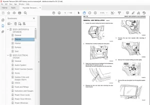
Removal 342
11 Remove cover (1, Figure 6), bolt and washer (2) with safety lever assembly (3) from control stand 343
Installation 347
Completing work 347
Removal and Installation of Cabin Glass 348
Removal of Cabin Glass 348
Installation of Cabin Glass 350
Installation of Upper Door Glass 353
Installation of Upper Front Glass 353
Counterweight 355
Safety Instructions 359
General 360
Warning for Counterweight and Front Attachment Removal 360
Removal 362
Installation 363
Hydraulic Oil Tank 365
Safety Instructions 369
General 369
Specification 369
Air Breather 370
Removal 371
• Hoses and plugs ports 377
• Fitting 378
Installation 379
Completing Work 380
Fuel Tank 381
Safety Instructions 385
General 385
Specification 385
Removal 386
• Keep open flames and ignition sources away from the workplace 386
Installation 392
Completing Work 393
1 Turn key to “OFF” position 393
2 Open right side door and locate fuel filter 393
3 Attach a clear plastic hose to the bleed nipple (1, Figure 25) on the fuel filter housing Place the end of the plastic hose in a container that hose at least 3 L (0 8 U S gal ) 393
4 Loosen the hand pump handle (2, Figure 25) 393
5 Open the bleed nipple (1, Figure 25) 393
6 Pump (2, Figure 25) by hand until fuel comes out of the hose This may take around 100 pump strokes Depending on the installation, a significantly greater number of pump strokes may be required before fuel comes out 393
7 Close the bleed nipple (1, Figure 25) 393
8 Start the engine and open the bleed nipple (1, Figure 25) carefully 393
9 Check that fuel without air bubbles comes out of the hose Normally, about 3 liters of fuel must be drained before no more air bubbles come through the hose 393
10 Close the bleed nipple (1, Figure 25), remove hose and tighten the hand pump handle (2) 393
Main Pump 395
Safety Instructions 399
Axial Piston Pump 399
Specifications 399
Overview 401
Hydraulic Circuit 403
Section View 404
Theory of Operation 406
• This pump assembly consists of two pumps connected by a spline coupling (113) The two pumps can be driven simultaneously as the rotation of the prime mover (engine) is transferred to the driveshaft (F) (111) on the front side The suction port s 406
• The rotary group consists of a driveshaft (F) (111), a cylinder block (13), a piston and shoes (11), a set plate (134), a spherical bushing (135) and a cylinder spring (136) The driveshaft is supported by bearings (121 and 122) at both ends The 406
• The swash plate group consists of a swash plate (211), a shoe plate (215) and a piston (11) The swash plate is supported by a cylindrical part formed on the opposite side of the sliding surface of the shoe 407
• The valve cover group consists of a main case (311), a plate valve (312) and a plate valve pin (352) The plate valve that has two cylindrical ports is mated to the main case, which feeds and collects oil to and from the cylinder block The oil c 407
Tools 408
Tightening Torque 409
Removal 410
• Hoses and plugs ports 419
• Fitting 419
Installation 421
Completing Work 421
Disassembly 422
Reassembly 425
Troubleshooting 428
Maintenance Instructions 430
Regulator 431
Port and Hydraulic Circuit 431
Functional Explanation 431
Functional Explanation 433
Adjustment of Flow Control Characteristic 435
Functional Explanation 435
• T in = P1 x q/2p + P2 x q/2p = (P1 + P2) x q/2p 435
Low Tilting Angle (Low Flow) Command Preferential Function 436
Adjustment of Input Horsepower 436
Functional Explanation 437
Adjustment 438
Tightening Torque 441
Tools 441
Section View 442
Disassembly 444
1 Choose a clean place 444
2 Spread rubber mat or cloth, on top of workbench to prevent parts from being damaged 444
4 Remove hex socket head screws (412,413) and regulator main body from pump main body 444
5 Remove hex socket head screws (488) and cover (C) (629) 444
6 After removing cover (C) (629) subassembly, remove outer spring (625), inner spring (626) and spring seat (C) (624) from compensating section Then draw out adjusting ring (Q) (645), pilot spring (646) and spring seat (644) from pilot section 445
8 Remove retaining ring (814), spring seat (653), return spring (654) and sleeve (651) 445
10 Remove lever (2) (613) Do not draw out pin (875) 446
Reassembly 447
3 Install spool (652) and sleeve (651) into hole in spool of casing 447
4 Install feedback lever (611), matching its pinhole with pinhole in spool Then insert pin (874) 447
5 Insert pilot piston (643) into pilot hole of casing 447
8 Insert adjusting plug (615) and install locking ring 448
Troubleshooting 450
Pilot Gear Pump 451
Specification 451
Theory of Operation 451
Port and Hydraulic Circuit 451
Precaution 452
Drive Coupling (Main Pump) 453
Safety Instructions 457
General 457
Specification 457
Section View 458
Tools 459
Disassembly 460
Reassembly 460
Main Control Valve 463
Safety Instructions 467
General 467
Specification 467
Overview 468
Theory of Operation 474
Neutral Passage 474
Signal Passage 478
Travel Spool Shift 480
Heel Spool Shift 480
Swing Spool Shift 482
Rotating Spool Shift 482
Boom Spool Shift 484
Arm Spool Shift 487
A 2-pump confluence 488
B Variable regeneration 489
Parallel Orifice for Arm 490
Relief Valve 491
Travel Compound Operation 492
Rotating Compound Operation 494
Swing Compound Operation 496
A The holding pressure of port (A5) is sent through passages (a, b, and c), and into spring chamber (d) of poppet (1) Now pressurized oil flow, from port (A5) is cut off by seats (S1 and S2) 498
Operation 500
Absorption Operation 501
Cautions for Operation 502
Precaution 503
Tools and Torques 503
Removal 504
Installation 518
Completing Work 519
Disassembly 520
Caution on Disassembly 520
Sequence of Disassembly 521
7 Disassembly of spool 521
1 This relief valve must be replaced as an assembly When replacing it, remove plug (1, width across flats: 32 mm), and O-ring (2) If oil is leaking from nut (4), remove nut (4) and plug (1), and replace O-ring (3) If oil is leaking from nut (7), 529
1 This relief valve must be replaced as an assembly When replacing it, remove cap (1, width across flats: 32 mm) and O-ring (2) If oil is leaking from nut (4), remove nut (4) and plug (1), and replace O-ring (3) If oil is leaking from nut (7), re 530
1 This unit has press install portion (D) and it must be replaced as a complete assembly 531
Cleaning and Inspection 532
Cleaning 532
Inspection 532
Reassembly 533
Caution on Assembly 533
Sequence of Subassembly 534
Maintenance of Relief Valves 545
1 Check if there is dirt and paint chips around threads of plug (1, 6 and 8) and nut (4 and 7) Replace O-ring with new one Clean installation portion of relief valve and valve housing Install valve, and then tighten plug (1, width across flats: 3 545
1 Check if there is dirt and paint chips around cap (1) Replace O-ring with new one Clean installation portion of relief valve and valve housing Install relief valve and tighten cap (1) Torque: 7 95 ~ 8 97 kg m (58 ~ 65 ft lb) Wrench 32 546
1 Check if there is dirt and paint chips around plug (1) Replace O-ring (3) with new one Install new O-ring (4) on sleeve (2) Clean installation portion of relief valve and valve housing Tighten plug (1, width across flats: 32 mm) of relief valv 547
Troubleshooting, Testing and Adjustment 548
Troubleshooting 548
Adjustment of Valves 550
A Loosen locknut (7) and turn adjusting plug (8) counterclockwise to lower relief pressure at state of 4 One turn varies pressure by approximately 213 bar (217 kg/cm2, 3,089 psi) Tighten locknut (7) after pressure has been adjusted 550
Swing Device 553
Safety Instructions 557
General 557
Specification 557
Overview 558
Theory of Operation 560
Cautions for Operation 568
Precaution 572
Tools for Disassembly and Assembly 572
Tightening Torque 572
Removal 574
Installation 579
Completing work 580
Section View 582
Swing Motor 582
Swing Reduction Gear 584
Disassembly 586
Swing Motor 586
Swing Reduction Gear 591
Reassembly 595
Swing Motor 595
Swing Reduction Gear 602
Troubleshooting 606
General Instructions 606
Examination of Hydraulic Motor 606
1) Lock the swing and supply high-pressure oil to the motor, and normal drain quantity must be approximately 25 LPM or less 606
Troubleshooting 607
Maintenance Instructions 610
Replacement Standard of Worn Parts 610
Standard of Sliding Surface Correction 610
Fan Pump for Oil Cooler 611
Safety Instructions 615
General 616
Specification 616
Overview 617
Theory of Operation 618
• Stand by pressure: 16 bar 618
• Pressure cut off: 120 bar (at 0 mA) 618
EPPR Valve 620
Control Curve (Pressure Compared to the Current Value) 620
• ED: Pressure compared to the current value 620
Control Curve (Pressure Compared to the Current Value) 621
Current Value According to the Temperature 622
Maintenance Guidelines 623
Sealing Driveshaft 624
Sealing Control Valve 626
Tools 626
• For all break-off plugs: #601 626
• For all other parts: #242 626
• Bolt tensile strength grade: 8 8, 10 9, 12 9 626
Removal 627
14 Remove hoses (Figure 32) (3 ea) from fan pump 630
• Hoses and plugs ports 630
• Fitting 630
Installation 631
Completing Work 631
Section View 632
EPPR Valve 632
Disassembly 633
Disassembly of Rotary Group 634
Disassembly of Control Device 635
Disassembly of Shaft/Bearings 636
Cleaning and Inspection 637
Reassembly 640
Adjustment of Taper Roller Bearing 641
Fan Motor for Oil Cooler 647
Safety Instructions 651
General 651
Specification 651
Overview 652
Parts List and Section View 653
Precaution 654
Tools 654
Removal 655
Installation 660
Completing Work 660
Disassembly 661
Reassembly 664
Reassembly 664
Assembly 665
Joystick Valve (Work Lever) 667
Safety Instructions 671
General 671
Specifications 671
Overview 672
Switches 673
Ports 673
Theory of Operation 674
1 Neutral position 674
2 Half-operated state 674
3 Fully operated state 675
Tools and Torques 675
Section View 676
Removal 678
Installation 683
Completing work 684
Disassembly 685
Reassembly 689
Travel Control Valve (with Damper) 695
Safety Instructions 699
General 700
Specification 700
Overview 701
Theory of Operation 702
Tools and Torques 703
Section View 704
Removal 705
Installation 710
Completing Work 711
Disassembly 712
2 Remove set screw (29) from cam (26) 712
Reassembly 715
15 Install bellows 719
Troubleshooting 720
Solenoid Valve 721
Safety Instructions 725
General 725
Specification 725
Overview 726
Parts List 728
Theory of Operation 729
Disassembly and Reassembly 730
2 For disassembly and reassembly, use torques and tools listed in tables 730
3 The directions of disassembly and reassembly are same as the “Disassembly Direction” and “Reassembly Direction” as shown in Figure 1 730
4 Disassembly and reassembly of the solenoid valve 730
A Remove coil locknut (2-1) from solenoid valve (2) 730
B Remove coil (2-2) by hand 730
C Remove solenoid valve (2) 730
D Check disassembled components for damage, and reassemble them in the reverse order of the disassembly 730
E Do not use excessive torque when assembling he solenoid valve and coil 730
5 Do not allow any contamination to enter the valve during disassembly and reassembly procedures 730
Troubleshooting 731
• Check if pressure is bypassing because of the presence of foreign substance 731
Accumulator 733
Safety Instructions 737
General 737
Specifications 739
Gear Pump (Rotation) 741
Safety Instructions 745
General 745
Specification 745
Overview 746
Location 746
Single Gear Pump 747
Disassembly 747
Reassembly 749
One Spool Valve (Rotating) 753
Safety Instructions 757
General 757
Specification 757
Overview 758
Theory of Operation 759
Disassembly and Assembly 761
General Cautions 761
Replacement of Spool 762
Replacement of Main Relief Valve 764
Replacement of Overload Relief Valve 765
Replacement of Sub-Block 767
Lower Structure and Chassis 769
Swing Bearing 771
Safety Instructions 775
General 776
General Description 776
Parts List 776
Maintenance Guidelines 777
Disassembly 778
Reassembly 780
1 Clean (degrease) the seal groove for the outer and inner seals (7) 780
2 Hoist the outer race by crane horizontally and match it with the inner race coaxially 780
3 Top plug (4) into outer race (1) and then, drive pin (3) into the pinhole 780
Center Joint 781
Safety Instructions 785
General 785
General Description 785
Overview 786
Section View 787
Removal 788
• Hoses and plugs ports 791
• Fitting 791
• Hoses and plugs ports 792
• Fitting 792
Installation 794
Completing Work 794
Disassembly 795
1 Clean off the exterior of the swivel joint after it has been removed 795
2 Scribe or otherwise mark a line across the cover and the body of the center joint, to allow reassembly in the same configuration 795
3 Remove oil remaining in each port with air 795
4 Use a 19 mm wrench to loosen cover bolts and washers (13 and 14, Figure 17) and remove cover (3) 795
5 Remove the shim (12, Figure 18) and O-ring (9) 795
6 Use a pliers to remove retaining ring and disassemble the spacer (4, Figure 19) and shim (11) at the back of the retaining ring (5) 796
9 Remove the O-ring (10, Figure 22) (1 ea), dust seal (7) (1 ea), O-ring (6) (1 ea) and slipper seal (8) (7 ea) from the hub (1) 797
Reassembly 798
1 Assemble the slipper seal (8, Figure 23) (7 ea), O-ring (6) (1 ea), O-ring (6) (1 ea) and dust seal (7) (1 ea) into the hub 798
4 Assemble the shim (11, Figure 25), spacer (4) and install the retaining ring (5) 799
5 Apply the grease inner surface of cover (3, Figure 26) to fix the shim (12) And install the O-ring (9) to hub 799
Troubleshooting, Testing and Adjustment 800
Inspection 800
Testing 800
• 700 bar (10,000 psi) pressure gauge 800
• Adapters, connectors, piping and flange block off plates conforming to those used in high-pressure piping connections of the excavator 800
• A high-pressure relief valve with a setting pressure 1 5 times maximum system pressure 800
• A stop valve 800
• A manually operated, in-line changeover valve 800
Travel Device 801
Safety Instructions 805
General 805
Specification 805
Overview 806
Theory of Operation 808
• How to release parking brake 811
Cautions for Operation 816
Selecting Hydraulic Oil 817
Inspection, Replacement of Hydraulic Oil 817
• Volume of hydraulic motor oil: about 2 ~ 2 5 L 817
• Replacement period: 2,000 hr or 1 year 817
Precaution 820
Tools for Disassembly and Assembly 820
Tightening Torque 822
Removal 823
• Hoses and plugs ports 827
• Fitting 827
Installation 829
Completing Work 829
Checkup After Assembly 830
Performance Test 831
Section View 832
Disassembly 836
General Caution Matters 836
Reduction Gear 836
Hydraulic Motor 842
Cleaning and Inspection 847
Maintenance Standard 847
Reassembly 849
General Caution Matters 849
Hydraulic Motor 849
Reduction Gear 857
Troubleshooting 865
Track Assembly 869
Safety Instructions 873
General 873
Track Tension 874
Track Shoes and Links 876
Track Removal 876
Track Installation 877
Track Shoe 878
Sprocket 880
Wear Limits and Tolerances 880
Front Idler 881
Front Idler Disassembly 881
Front Idler Reassembly 883
Upper Roller 884
Overview 884
• Wight: 40 kg (88 lb) 884
Upper Roller Removal 885
Upper Roller Installation 885
Upper Roller Disassembly 886
Upper Roller Reassembly 887
Wear Limits and Tolerances 888
Lower Roller 889
Overview 889
• Weight: 75 kg (165 lb) 889
Lower Roller Removal 890
Lower Roller Installation 890
Lower Roller Disassembly 891
Lower Roller Reassembly 892
Wear Limits and Tolerances 893
Track Adjuster 894
Disassembly 894
Assembly 895
Front 897
Boom and Stick 899
Safety Instructions 903
Specifications 904
Size and Weight 905
Removal 906
Stick Removal 906
Boom Removal 908
Installation 909
Stick Installation 909
Boom Installation 909
Start-up Procedures 909
Cylinders 911
Safety Instructions 915
General 915
General Description 915
Theory of Operation 916
Seal of Cylinder 917
Special Tools and Materials 919
Piston Nut 919
Piston Jig 920
Steel Bushing Jig 921
Dust Wiper Jig 922
Slipper Seal Jig 923
Slipper Seal Straightening Jig 924
Rod Bushing (DD-bushing) Pushing-in Jig 925
Disassembly 926
Reassembly 931
• Inspect and replace damaged or excessively worn parts 931
• Clean parts and lubricate with clean hydraulic oil 931
• Make sure work area is clean 931
Troubleshooting 935
Hydraulic System 937
Hydraulic System 939
Safety Instructions 943
General 943
General Description 943
Hydraulic Schematic 944
General Description 944
• As shown in the schematic, the main pump assembly is driven by the engine Mechanical energy is converted to hydraulic power, generating the required hydraulic flow which drives the system Two main pumps (a front pump and a rear pump) make up th 944
• Hydraulic output from the front pump is transmitted to the right side of the control valve Output from the rear pump is transmitted to the valve spools on the left side of the control valve Hydraulic output from the pilot pump is used to contro 944
• The right half of the hydraulic control valve, supplied by the front pump in the pump assembly, operates valve spools for right travel, swing, boom 2 and arm functions The amount of oil flow to the actuators at the output end of each of those ci 944
• The left half of the hydraulic control valve, supplied by the rear pump in the pump, has control spools for left travel, rotating, boom and arm 2 operation 944
• Two-stage operation is a feature of boom and arm function All of these circuits can be operated using the output of only one half of the hydraulic pump assembly (one pump or the other), or – since both halves of the control valve have a spool 944
• Whenever the right travel or left travel control spools are shifted, output from the main pump assembly flows through the center joint to one or both of the axial piston motors driving the side frame crawler tracks A pilot valve connected to the 944
• The hydraulic reservoir return line and the pilot circuit both have 10 micron full flow filters The disposable elements in these two canister type filters trap and remove impurities from the oil in the system An 80 mesh, 177 micron reservoir in 944
• Boom, Arm, and Heel cylinder circuit are also protected by overload relief valves Whenever high-pressure is generated because of a shock or overload, excess pressure is dumped to the reservoir return circuit through the relief valve 945
Hydraulic Component and Oil Flow 946
Hydraulic Components 946
Safety Cutoff Valve Operation 948
Power Up Valve Operation 950
Travel High-speed Valve Operation 952
Operation of high-speed 953
Swing Brake Release Operation 954
Two Pump Valve Operation 956
Travel Forward and Backward Operation 957
Boom Up Operation 958
Boom Down Operation 960
Arm (Stick) In Operation 962
Arm (Stick) Out Operation 964
Heel Rack In Operation 966
Heel Rack Out Operation 968
Hydraulic System Testing and Adjustment 971
Safety Instructions 975
Procedural Troubleshooting Baseline Recommendations 976
Initial Checks and Tests to Establish Operating Condition of the Excavator 976
• First hydraulic flow 976
• Then hydraulic pressure in a specified order of priority through different points of the system 976
• at 1,950 rpm with no load 976
• at 1,950 rpm stall load 976
• Pilot pressure 976
• Negacon, negative control pressure 976
• Main relief pressure (front and rear pump) 976
• Swing pressure 976
• Port relief pressure (individual control functions; boom, arm, bucket, swing, and travel) 976
• Power boost circuit 976
• Standard performance tests; cylinder speed, hydraulic motor (travel and swing) speed, cylinder oil tightness “permissible drift” test 976
Pilot Pressure 978
Adjustment and Testing 978
Power Mode Valve 979
Current Signal and Hydraulic Pressure Adjustments 979
Pressure Up Valve 980
Checks and Adjustments 980
• Check pilot pressure and readjust it, if required: 980
• Select the Instrument Panel rear pump “pressure display” 980
• Select Power Mode 980
• Stall the boom cylinder (towards the extend side) 980
• Read rear pump pressure on the Instrument Panel display 980
Pump Input Power Control 982
Pump Regulator Adjustment 982
• Verify engine output to the rated speed – 2,050 ±50 rpm 982
• Permanently mark setscrew positions at the current regulator control setting 982
• If the engine is being consistently overloaded (and engine troubleshooting shows engine performance to be at or above rated output) 982
• If reduced cylinder speed and diminished work performance provide an indication that rated, maximum pump flow may not be available (and all other troubleshooting gives no indication of other flaws or hydraulic system defects) 982
• If pump output is out of balance and one pump is failing to keep up with the output flow of the other 982
Flow Meter and Flow Meter Kit Installation and Testing 985
• Stop engine and operate controls to release hydraulic pressure from the accumulator 985
• Vent the reservoir to release all pressure from the hydraulic system 985
• Remove guard panels from around the main pump assembly 985
• Disconnect the main pump discharge output line Install the input flange of the flow meter on the pump end of the output line 985
• Cap off the unused (input) end of the pump discharge line with a blocking flange 985
• Connect a premeasured length of hydraulic hose, between the output end of the flow meter assembly and the top of the reservoir Use appropriate fittings and adapter flanges to guarantee a pressure tight seal 985
• An assistant – who must remain at the operator’s control station always – should restart the engine and run it long enough (at minimum rpm) to deaerate the system and warm up the engine and hydraulic system to operating temperature 985
• Unloaded maximum engine speed baseline test (all controls in neutral) 986
• Front pump test – operate “travel right” lever Record values at all specified pressures 986
• Rear pump test – operate “travel left” lever Record values at all specified pressures 986
Swing System Troubleshooting 987
Precautions/Initial Checks 987
Swing Relief Valve Checking and Adjustment 988
• The swing motor fails to turn 988
• Swings in one direction only 988
• Swings but continues to coast 988
• There is drifting on a slope 988
Hydraulic System Troubleshooting 991
Safety Instructions 995
Hydraulic System 995
Unusual Noise Comes Out from Pump Connection 995
Engine Starts but Machine Does Not Operate 996
Hydraulic Oil is Cloudy 997
Hydraulic Oil Overheated 997
Hydraulic Pump Cavitation 998
Hydraulic Oil is Contaminated 998
Boom, Arm, Bucket Speed is Slow 999
Boom, Arm or Bucket Power is Weak 1000
Cylinder Moves When Remote Control Valve is in the Neutral Position 1000
TR (L), TR (R) Swing Does Not Operate When Remote Control Valve Operated 1001
Swing Speed is Slow 1002
Machine Swings but Does Not Stop 1003
One Side Speed is Falls and the Machine Curves 1004
Machine Does Not Stop on a Slope 1005
Travel Motor is Powerless (Travel Only) 1005
Machine Makes a Curved Travel, When Travel and Actuator Operation are Executed a the Same Time 1006
Does Not Travel is 2nd Speed or Auto Speed 1006
Troubleshooting – Swing Gearbox 1007
Troubleshooting – Hydraulic Problems 1008
Troubleshooting – Control Valve 1010
Troubleshooting – Travel Control Valve 1011
Troubleshooting – Joystick Control Valve 1012
Electrical System 1013
Electrical System 1015
Introduction 1021
Electrical Supply System 1022
1 Terminal “5” of stereo 1022
3 Hour meter 1022
4 Engine controller (ECU + SCU) 1022
5 Terminal “2” of fuel auto shutoff controller 1022
6 Terminal “6” of wiper motor 1022
8 Terminal “CN7-5, CN7-6” of instrument panel controller 1022
9 Terminal “CN9-6” of air conditioner panel 1022
10 Cabin light 1022
Engine Starting Circuit 1024
Start Operation 1024
After Start 1026
Engine Preheating System 1028
Engine Stop 1030
Charging System 1032
Monitoring System 1033
Instrument Panel 1034
Functional Check 1034
Monitoring System Schematic 1036
Operation 1038
Instruments 1038
Warning and Indicator Lights 1040
Indication of Warning Lights 1040
Indication of Multifunction Gauge 1043
Initial Operation 1045
Graphic Information Area Display 1046
Overview 1046
3 Letter Information Display Department 1046
Main Menus for the Graphic Display Area 1046
Menu Selector Buttons 1046
User Menu 1047
User Menu – Access and Escape Methods 1047
Switch Operation Indication 1084
Special Menu 1087
Entering/Accessing and Exiting/Escaping Menus 1087
Special Menu Selections 1088
User Selection Signal 1094
Graph Data Monitoring 1094
Graph Data Setting 1095
“Occurrence Time”: It indicates the period for which machine has operated until a fault takes place (For more than two occurrences of the same fault, until first occurrence time ) 1097
Operation Hour Information 1098
Option Setting 1101
Failure Code 1105
Failure Code at Machine 1105
Failure Code at Engine Side 1108
Electronic Hydraulic Control System (EPOS) 1128
Control System Schematic 1128
Power Plus Mode Control 1130
Operation 1132
Power Mode Control 1134
i-CEPT (Intelligent Construction Equipment of Power) System 1136
Smart Power Control (SPC) 1137
Operation 1137
SPC Diagram 1139
SPC Circuit 1140
Engine Control System 1141
Engine Control Dial 1142
Engine Control 1144
Automatic Deceleration Control (Auto Idle Control) 1146
Engine Overheat Protection System 1148
Power Boost Mode 1151
Operation 1151
Power Boost Control 1152
Automatic Travel Speed Control 1154
Automatic Travel Speed Control 1156
Water in Fuel Warning System 1157
Operation 1157
Self-diagnostic Function 1158
EPOS Controller 1158
Air Conditioner System 1160
Outline 1160
Internal and External Filters 1161
Air-Conditioning System Layout 1162
Air Conditioner/Heater Circuit Diagram 1163
Air Conditioner/Heater Unit 1164
Ambient Air Temperature Sensor 1169
Control Panel 1170
Receiver Dryer 1177
Troubleshooting 1178
Refrigerant System Repairs 1180
Refrigerant Safe Handling Procedures 1180
Repair and Replacement Procedure 1181
Refrigerant Recovery 1183
Vacuuming Refrigerant System 1183
Leakage Check 1185
Refrigerant Charging 1185
• Always keep refrigerant supply container in the upright position 1186
• Never open the high side pressure valve 1186
• When outside temperature is low, warm the refrigerant supply container with warm water not exceeding 40°C (104°F) Do not allow water to come in contact with the charging adapter valve handle 1186
• When outside temperature is high, cool off refrigerant supply container and condenser to aid the refrigerant charging process 1186
Inspecting System For Leakage 1187
Wiper System 1188
Wiper Circuit 1188
Wiper Operation 1189
Lighting System 1192
Lighting System Circuit Diagram 1192
Kind of Light 1193
Operation 1193
Overload Warning Device 1194
Overload Warning Device Circuit Diagram 1194
Audio Controller 1195
Audio Controller Circuit Diagram 1195
Schematic 1197
Hydraulic Schematic/ Electrical Schematic 1199
DX300LL-5 (Road Builder)Hydraulic Schematic 1201
DX300LL-5 (Log Loader)Hydraulic Schematic 1202
DX300LL-5 Electrical Schematic 1203
DX300LL-5 (Oregon Cabin)Electrical Schematic 1204
DX300LL-5 (Road Builder – Oregon Cabin)Electrical Schematic 1205
DX300LL-5 (Road Builder – ROPS)Electrical Schematic 1206
DESCRIPTION:
Hyundai HX300LL Excavator Shop Manual 2023 – PDF DOWNLOAD
GENERAL:
Safe Operation is Operator’s Responsibility:
Only trained and authorized personnel should operate and maintain the machine.
Follow all safety rules, regulations and instructions when operating or performing maintenance on machine.
• Do not operate machine if you are under the influence of drugs or alcohol. An operator who is taking prescription
drugs must get medical advice to determine if he or she can safely operate a machine.
• When working with other personnel on a work site, be sure that all personnel know nature of work and understand all
hand signals that are to be used.
• Be sure that all guards and shields are installed in their proper location. Have guards and shields repaired or
replaced immediately if damaged.
• Be sure that you understand the use and maintenance of all safety features such as safety lever and seat belt. Use
them properly.
• Never remove, modify or disable any safety features. Always keep them in good operating condition.
• Always check for and know the location of underground and overhead utility lines before excavating.
• Failure to use and maintain safety features according to instructions in this manual, Safety Manual and Shop Manual can result in death or serious injury.
Questions? Email us: [email protected]
https://vimeo.com/916408503?share=copy
S.V