Hyundai Robex 140LS Smart Excavator Repair Manual PDF
Original price was: $120.00.$31.95Current price is: $31.95.
Official Hyundai Service Manual for Robex 140LS Smart hydraulic excavator. 571 pages packed with specifications, hydraulic/mechatronics systems, troubleshooting guides, performance tests, full disassembly/assembly procedures, torque specs, and detailed diagrams – indispensable hyundai robex 140ls service manual pdf for repairs and maintenance.
Description
Hyundai Robex 140LS Smart Excavator Service Manual PDF DOWNLOAD
Description
This is the official Hyundai Construction Equipment Service Manual for the Robex 140LS Smart Hydraulic Excavator. Spanning 571 pages, this comprehensive factory resource provides in-depth technical details on every system, making it essential for professional technicians, fleet operators, and owners performing maintenance or repairs on the hyundai robex 140ls service manual pdf, robex 140ls smart excavator repair manual needs.
Covering structure, hydraulics, electrics, mechatronics (CAPO system), troubleshooting, performance standards, and complete hyundai r140ls disassembly assembly guide procedures – including robex 140ls troubleshooting hydraulic system pdf charts, r140ls swing device maintenance download instructions, and hyundai excavator main control valve manual specifics.
Table of Contents – Fully Organized
SECTION 1 GENERAL
- Group 1 Safety Hints ………………………………………………………………………. 1-1
- Group 2 Specifications ………………………………………………………………………. 1-10
SECTION 2 STRUCTURE AND FUNCTION
- Group 1 Pump Device ………………………………………………………………………. 2-1
- Group 2 Main Control Valve ……………………………………………………………… 2-20
- Group 3 Swing Device ………………………………………………………………………. 2-43
- Group 4 Travel Device ………………………………………………………………………. 2-55
- Group 5 RCV Lever ………………………………………………………………………….. 2-80
- Group 6 RCV Pedal ………………………………………………………………………….. 2-87
SECTION 3 HYDRAULIC SYSTEM
- Group 1 Hydraulic Circuit ………………………………………………………………….. 3-1
- Group 2 Main Circuit …………………………………………………………………………. 3-2
- Group 3 Pilot Circuit ………………………………………………………………………….. 3-5
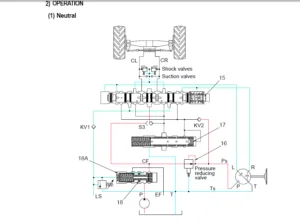
- Group 4 Single Operation ………………………………………………………………….. 3-12
- Group 5 Combined Operation …………………………………………………………… 3-22
SECTION 4 ELECTRICAL SYSTEM
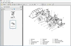
- Group 1 Component Location …………………………………………………………… 4-1
- Group 2 Electrical Circuit …………………………………………………………………… 4-3
- Group 3 Electrical Component Specification ………………………………………. 4-21
- Group 4 Connectors …………………………………………………………………………. 4-29
SECTION 5 MECHATRONICS SYSTEM
- Group 1 Outline ……………………………………………………………………………….. 5-1
- Group 2 Mode Selection System ………………………………………………………… 5-3
- Group 3 Automatic Deceleration System ……………………………………………. 5-5
- Group 4 Power Boost System ……………………………………………………………. 5-6
- Group 5 Travel Speed Control System …………………………………………………. 5-7
- Group 6 Automatic Warming Up Function ……………………………………………. 5-8
- Group 7 Engine Overheat Prevention Function ……………………………………. 5-9
- Group 8 Anti-Restart System ………………………………………………………………. 5-10
- Group 9 Self-Diagnostic System ………………………………………………………… 5-11
- Group 10 Engine Control System ………………………………………………………… 5-14
- Group 11 EPPR Valve ………………………………………………………………………. 5-20
- Group 12 Monitoring System ……………………………………………………………… 5-23
SECTION 6 TROUBLESHOOTING
- Group 1 Before Troubleshooting ………………………………………………………… 6-1
- Group 2 Hydraulic and Mechanical System …………………………………………. 6-4
- Group 3 Electrical System …………………………………………………………………. 6-24
- Group 4 Mechatronics System …………………………………………………………… 6-39
SECTION 7 MAINTENANCE STANDARD
- Group 1 Operational Performance Test ………………………………………………… 7-1
- Group 2 Major Components ……………………………………………………………….. 7-21
- Group 3 Track and Work Equipment …………………………………………………… 7-31
SECTION 8 DISASSEMBLY AND ASSEMBLY
- Group 1 Precaution …………………………………………………………………………….. 8-1
- Group 2 Tightening Torque …………………………………………………………………… 8-4
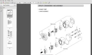
- Group 3 Pump Device …………………………………………………………………………… 8-7
- Group 4 Main Control Valve ………………………………………………………………….. 8-29
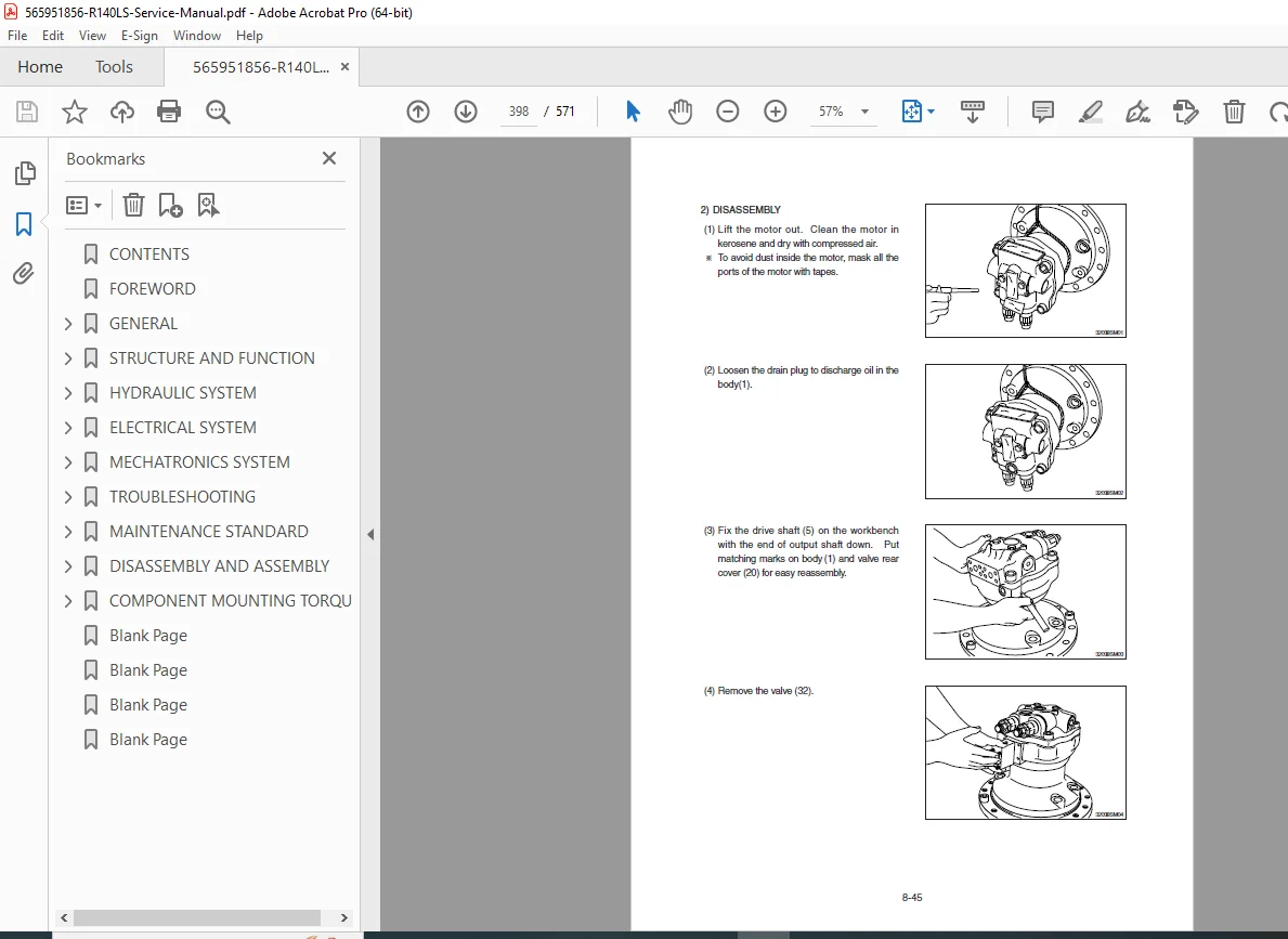
- Group 5 Swing Device ………………………………………………………………………….. 8-43
- Group 6 Travel Device ………………………………………………………………………….. 8-64
- Group 7 RCV Lever ……………………………………………………………………………… 8-119
- Group 8 Turning Joint …………………………………………………………………………… 8-134
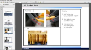
- Group 9 Boom, Arm and Bucket Cylinder ………………………………………………… 8-139
- Group 10 Undercarriage ………………………………………………………………………. 8-156
- Group 11 Work Equipment …………………………………………………………………… 8-168
SECTION 9 COMPONENT MOUNTING TORQUE
- Group 1 Introduction Guide …………………………………………………………………. 9-1
- Group 2 Engine System ……………………………………………………………………….. 9-2
- Group 3 Electric System ……………………………………………………………………….. 9-4
- Group 4 Hydraulic System …………………………………………………………………… 9-6
- Group 5 Undercarriage ……………………………………………………………………….. 9-9
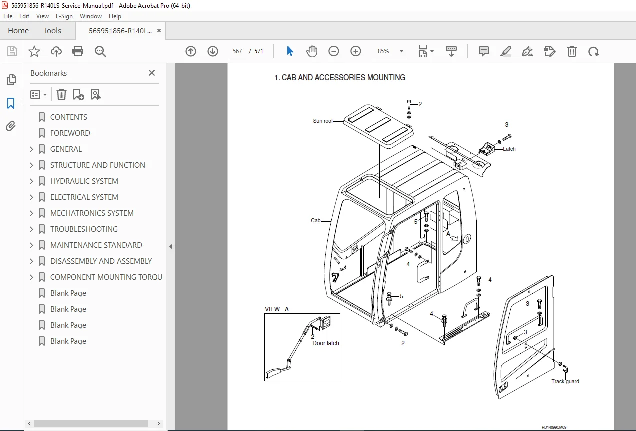
- Group 6 Structure ………………………………………………………………………………. 9-10
- Group 7 Work Equipment ……………………………………………………………………. 9-14
File Details
- Manual Name: Hyundai Robex 140LS Smart Hydraulic Excavator Service Manual
- Models Covered: Robex 140LS Smart
- Year: Factory original (professional construction equipment era)
- PDF Quality: High-resolution scanned pages with clear text, diagrams, schematics, and tables
- Number of Pages: 571
Master every aspect of your Hyundai Robex 140LS Smart with this complete factory manual – from routine service to major overhauls. Instant digital download means you can start diagnosing and repairing with confidence today!