Hyundai Yanmar 3TNV 4TNV Engine Base Service Manual – PDF DOWNLOAD
Original price was: $79.95.$28.95Current price is: $28.95.
Hyundai Yanmar 3TNV 4TNV Engine Base Service Manual – PDF DOWNLOAD
Description
Hyundai Yanmar 3TNV 4TNV Engine Base Service Manual – PDF DOWNLOAD
IMAGES PREVIEW OF THE MANUAL:


HYUNDAI YANMAR 3TNV 4TNV ENGINE BASE SERVICE MANUAL – PDF DOWNLOAD:
DESCRIPTION:
Hyundai Yanmar 3TNV 4TNV Engine Base Service Manual – PDF DOWNLOAD
PREFACE:
- This manual describes the service procedures for the TNV series engines of indirect injection system. that have been certified by the US EPA, California ARB and/or the 97/68/80 Directive for industrial use. Please use this manual for accurate, quick and safe servicing of the said engine.
- Since the explanation in this manual assumes the standard type engine, the specifications and complements may partially be different from the engine installed on individual work equipment (power generator. pump. compressor, etc). Please also refer to the service manual for each work equipment for details. The specifications and components may be subject to change for improvement of the engine quality without notice. If any modification of the contents described herein becomes necessary, it will be notified in the form of correction information each time.
SAFETY LABELS
• Most accidents are caused Ьу negligence of basic safety ru!es and precautions. For accident prevention, it is important to avoid such causes before development to accidents. Please read this manual carefully before starting repair ог maintenance to fully
understand safety precautions and appropriate inspection and maintenaпce procedures.
Attempting at а repair or maintenance job without sufficient knowledge тау cause an unexpected accident.
• It is impossiЫe to cover every possiЬ/e danger in гераiг or maintenance in the manual. Sufficient consideration for safety is requir(?d in addition to the matters marked [ А CAUTION J. Especially for safety precautions in а repair ог maintenance job not described in this manual, receive instructions from а knowledgeaЫe leader.
TABLE OF CONTENTS:
Hyundai Yanmar 3TNV 4TNV Engine Base Service Manual – PDF DOWNLOAD
1 General 1
1 1 Engine Nomenclature 1
1 2 Specifications 1
1 3 Fuel Oil, Lubricating Oil and Cooling Water 14
1 3 1 Fuel oil 14
1 3 2 Lubricating oil ? 15
1 3 3 Cooling water 15
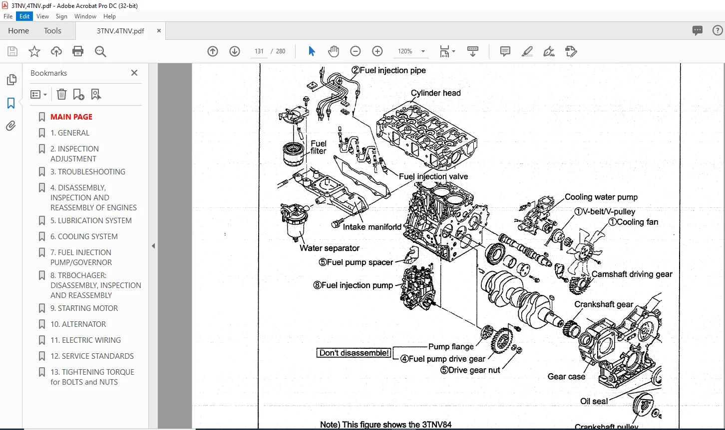
1 4 Engine External Views 16
1 5 Structural Description 17
1 6 Exhaust gas emission regulation 18
1 6 1 The Emission Standard in USA 18
1 6 2 Engine identification 19
1 6 3 Guarantee Conditions for the ЕРА Emission Standard 20
2 lnspection and Adjustment ·22
2 1 Periodic Maintenance S chedule 22
2 2 Periodic lnspection and Maintenance Procedure 23
2 2 1 Check before Daily Operation 23
2 2 2 inspection after initial 50 hours operation 25
2 2 3 lnspection every 50 hours 28
2 2 4 lnspection every 250 hours or 3 months 32
2 2 5 lnspection every 500 hours ог 6 months 35
2 2 6 lnspection every 1,000 hours or one year 37
2 2 7 lnspection every 2000 hours ог 2 years :: 46
2 3 Adjusting the no-load maximum or minimum speed 49
2 4 S ensor lnspection 50
2 4 1 Oil pressure switch 50
2 4 2 Thermo switch 50
2 5 Water leak check in cooling water system i 50
2 6 Radiator сар inspection 51
2 7 T hermostat lnspection 51
2 8 Adjusting Operation 52
2 9 Long storage 52
З TROUBLESHOOTING 53
3 1 Preparation before trouЫeshooting 53
3 2 Quick Reference ТаЫе for TrouЫeshooting 54
3 3 TrouЫeshooting Ьу measuring Compression Pressure 57
4 DisassemЫy, lnspection and ReassemЫy of Engines 59
4 1 Complete disassemЬ\y and reassemЫy 59
4 1 1 lntroduction 59
4 1 2 Special service tools 60
4 1 З Complete disassemЫy 65
4 1 4 Precautions before and during reassemЫy 69
4 1 5 Adjusting operation 6 9
4 2 Cylinder Head: DisassemЫy, lnspection and ReassemЬ\y 70
4 2 1 Components 2( -valve cylinder head) 70
4 2 2 DisassemЬ\y procedure: 70
4 2 З ReassemЫy procedure: 71
4 2 4 Servicing points 72
4 2 5 Parts lnspection and measurement 76
4 2 6 Valve seat correction 80
4 2 7 Valve guide replacement 81
4 2 8 Valve stem seal replacemen t 82
4 3 Gear Train and Camshaft 83
4 3 1 Components 83
4 3 2 DisassemЫy procedure: 83
4 З З ReassemЫy procedure: ? ?· • 8 3
4 3 4 Servicing points 84
4 З 5 Parts inspection and measurement 87
4 З 6 Oil seal replacement (Gear case side) 89
4 3 7 Camshaft bushing replacement 89
4 4 Cylinder Block · • 90
4 4 1 Components ? -: 90
4 4 2 DisassemЫy procedure: 9 0
4 4 3 ReassemЫy procedure: 90
4 4 4 Servicing points 91
4 4 5 Parts inspection and measurement 95
4 4 6 Cylinder bore correction ·······················································································#·•··· ·········· 106
4 4 7 Piston pin bushing replacement 107
4 4 8 Oil seal replacement (Flywheel housing side) 107
5 LUBRICATION SYSTEM 108
5 1 Lubrication System Diagram 108
5 2 Trochoid Pump Components 109
5 3 DisassemЫy(Reverse the procedure below for assemЫy) 109
5 4 Servicing Points 109
5 5 Parts lnspection and Measurement 110
5 5 1 Trochoid pump inspection and measurement 110
6 COOLING SYSTEM 112
6 1 Cooling Water System 112
6 2 Cooling Water Pump Components 112
6 3 DisassemЫy (Reverse the procedure below for assemЬ/y) 113
6 4 Servicing Points 11 З
7 FUEL INJECTION PUMP/GOVERNOR 114
7 1 lntroduction 114
7 2 Fuel lnjection Pump · 114
7 2 1 Fuel system diagram ················································································?···························1 14
7 2 2 External view and components 115
7 2 3 DisassemЫy procedure: 115
7 2 4 AssemЫy procedure 116
7 2 5 Servicing points 116
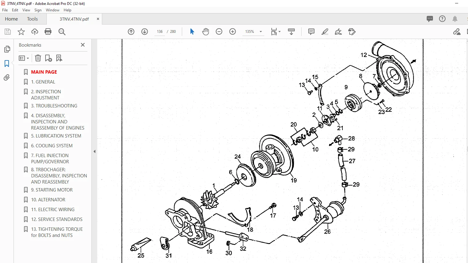
8 TURBOCHAGER: DisassemЫy, inspection and reassemЫy 118
8 1 Structure and Functions 118
8 1 1 Main specifications 118
8 1 2 Construction 118
8 1 3 Structural and functional outline ? 119
8 1 4 Components 120
8 2 Service Standards and Тightening Torque 121
8 2 1 Service standards 121
8 2 2 Тightening torque 122
8 3 Periodic lnspection Procedure :············ ··········1 23
8 3 1 Periodic inspection intervals 123
8 3 2 lnspection procedure 124
8 3 3 Waste gate valve adjustment procedure 125
8 4 DisassemЫy Procedure 127
8 4 1 Preparation for disassemЫy 1 27
8 4 2 lnspection before disassemЫy 128
8 4 3 DisassemЫy 128
8 5 Washing and lnspection procedure 130
8 5 1 Washing 130
8 5 2 inspection procedure 131
8 6 ReassemЫy Procedure 134
8 6 1 Preparation for reassemЫy 134
8 6 2 ReassemЫy 134
87 Handling after DisassemЫy and ReassemЫy 137
8 7 1 lnstructions for turbocharger installation 137
8 8 TrouЫeshooting 138
8 8 1 Excessively exhaust smoke 138
8 8 2 White smoke generation 138
8 8 3 Sudden oil decrease 139
8 8 4 Decrease in output 139
8 8 5 Poor (slow) response ( starting) of turbocharger 139
8 8 6 Abnormal sound ог vibration 139
9 ST ARTI NG MOTOR 140
9 1 For4 TNV94U98 140
9 1 1 Specifications 140
9 1 2 Components 141
9 1 З TrouЫeshooting 142
9 1 4 Names of parts and disassemЫy procedure 1 43
9 1 5 lnspection and Maintenance 147
9 1 6 Service standards 152
9 1 7 AssemЫy 153
9 1 8 Characteristic tes t 155
9 2 For4 TNV10 6(T) – : 15 6
9 2 1 Specifications 156
9 2 2 Congiguration drawing 156
9 2 3 TrouЫeshooting 157
9 2 4 Component names and disassemЫy procedure 158
9 2 5 DisassemЫy procedure ? 1 59
9 2 6 lnspection and maintenance 1 67
9 2 7 AssemЫy 173
9 2 8 Adjustment ? 174
9 2 9 Service standards 175
1 О AL TERNATOR 176
1 О 1 The 40А Alternator for ЗTNV84 and other models 176
10 1 1 Components 176
1 О 1 2 Specifications – 177
10 1 З Wiring diagram 177
10 1 4 Standard output characteristics 178
10 1 5 lnspection 178
10 2 TrouЫeshooting : 179
11 ELECTRIC WIRING 180
11 1 Electric Wiring Diagram 180
11 2 PRECAUTION O N ELECTRIC WIRING 181
11 2 1 Alternator 181
11 2?2 Starter ·182
11 2 З Current limiter 183
11 2 4 Section area and resistance of electric wire 184
12 SERVICE STANDARDS 185
12 1 Engine Tuning 185
12 2 Engine Body 186
12 2 1 Cylif\der head : 186
12 2 2 Gear train and camshaft 189
12 2 3 Cylinder Ыосk 190
12 З Lubricating Oil System (Trochoid Pump) 195
12 З 1 Outside clearance of outer rotor 195
12 3 2 Side clearance of outer rotor 195
12 3 3 lnside clearance of inner rotor 195
12 3 4 Rotor shaft ctearance 195
13 TIGHTENING TORQUE for BOLTS and NUTS 196
13 1 Тightening Torques for Main Bolts and Nuts 196
13 2 Тightening Torques for Standard Bolts and Nuts 197
PLEASE NOTE:
- This is the same manual used by the DEALERSHIPS to SERVICE your vehicle.
- The manual can be all yours – Once payment is complete, you will be taken to the download page from where you can download the manual. All in 2-5 minutes time!!
- Need any other service / repair / parts manual, please feel free to contact us at heydownloadss @gmail.com . We may surprise you with a nice offer
S.V