
Icom IC-745 HF All Band Transceiver Maintenance Manual – General Coverage Receiver Service Guide
Original price was: $34.95.$19.95Current price is: $19.95.
Complete Icom IC-745 maintenance manual covering the HF all band transceiver and general coverage receiver – circuit descriptions, PLL alignment, board layouts, voltage diagrams, parts lists and full adjustment procedures in a downloadable PDF.
Description
Icom IC-745 Maintenance Manual – HF All Band Transceiver & General Coverage Receiver
This Icom IC-745 maintenance manual is the full technical service document for the HF all band transceiver and general coverage receiver. It walks a technician through the receiver, transmitter, PLL and logic circuits, then hands over the complete bench adjustment routines, board layouts, voltage diagrams, IC ratings, parts lists and schematic diagrams needed to keep the radio on frequency and on the air. Every section is written around the actual IC-745 hardware – from the 70.4515 MHz first IF down to the 455 kHz third IF and the dual-loop PLL that drives the 1st LO.
File Details
- Manual type: Maintenance / Service Manual
- Brand: ICOM
- Model: IC-745
- Equipment covered: HF All Band Transceiver and General Coverage Receiver
- Language: English
- File format: PDF
- Page count: 126 pages
- Publisher: ICOM Incorporated, Osaka, Japan
Chapters Covered
- 1. Specifications
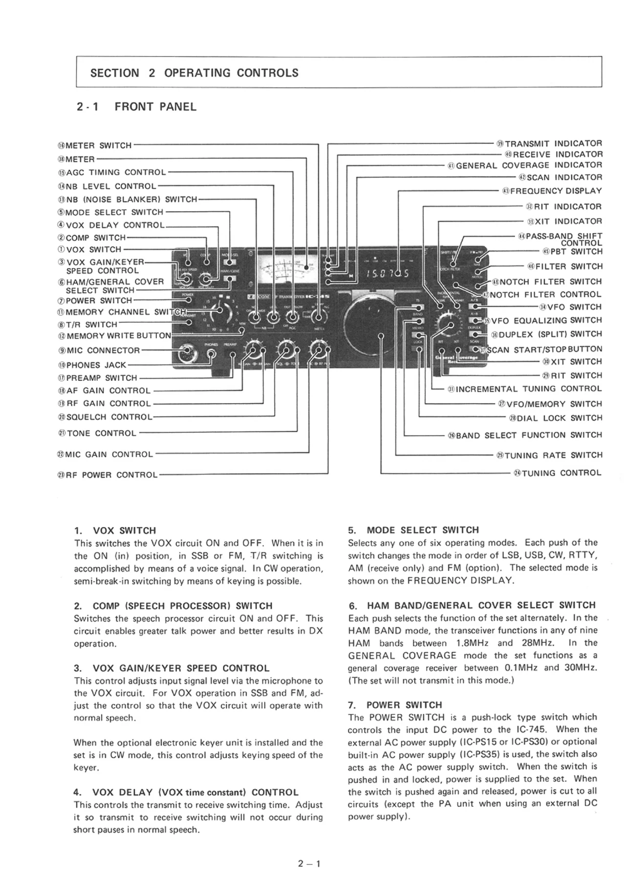
- 2. Operating Controls
- 2-1 Front Panel
- 2-2 Top Cover
- 2-3 Rear Panel Connections
- 3. Operating Instructions
- 3-1 How to Tune
- 3-2 Memory Channel Operation
- 3-3 Tuning by UP/DOWN Buttons on the Microphone
- 3-4 Scanning Operation
- 3-5 SSB Operation
- 3-6 CW Operation
- 3-7 RTTY Operation
- 3-8 AM Operation
- 3-9 FM Operation (Option)
- 3-10 General Coverage Receiver
- 3-11 Other Operations
- 4. Circuit Description
- 4-1 Receiver Circuits
- 4-2 Transmitter Circuits
- 4-3 PLL Circuits (Main Loop and Sub Loop)
- 4-4 Logic Circuits (CPU, Display, Matrix)
- 4-5 Other Circuits (2nd LO, Display Unit)
- 5. Block Diagram
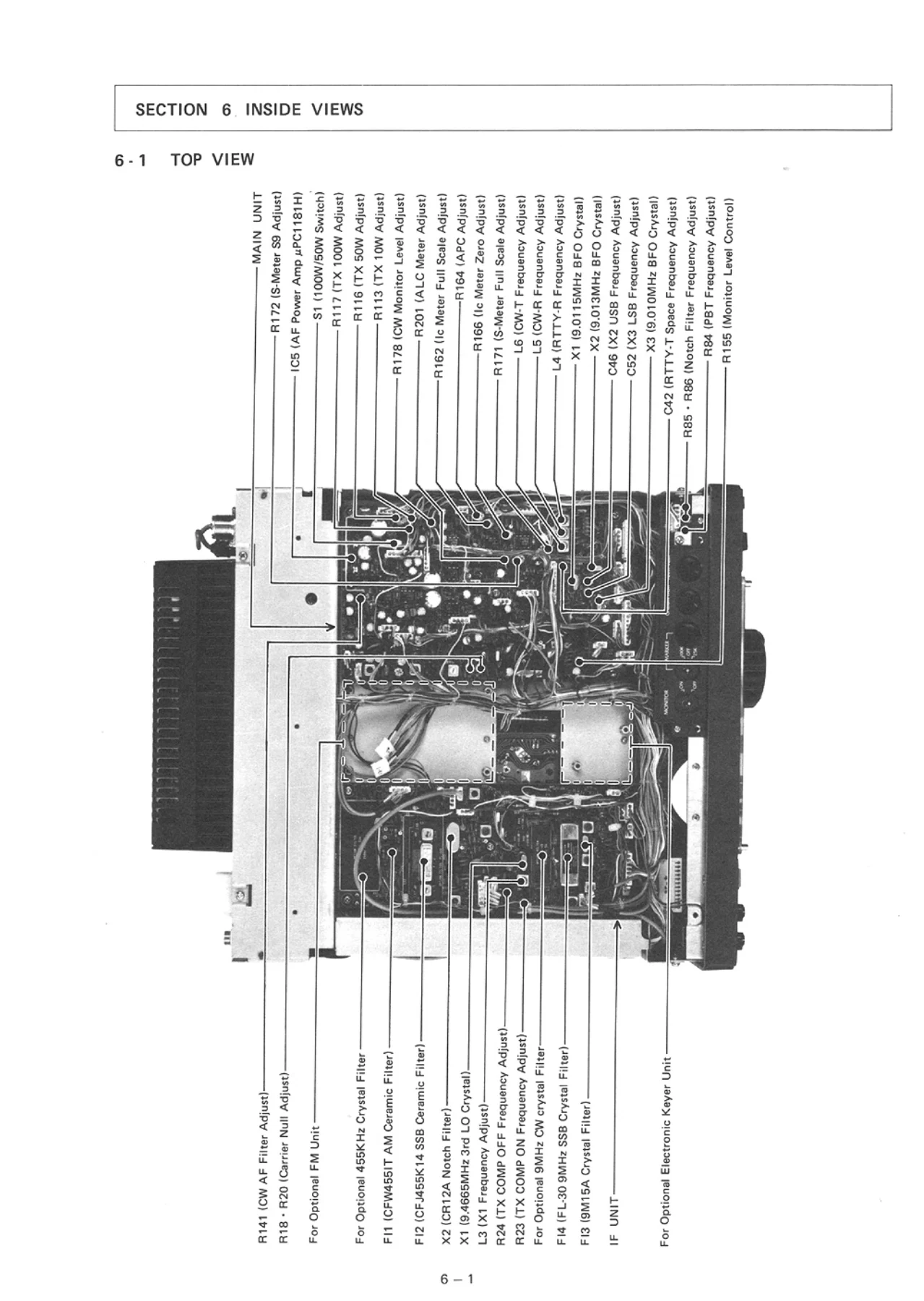
- 6. Inside Views (Top View and Bottom View)
- 7. Options Installation
- 7-1 Optional Filter Installation
- 7-2 Marker Unit IC-EX241
- 7-3 FM Unit IC-EX242
- 7-4 Electronic Keyer Unit IC-EX243
- 7-5 Built-in Power Supply Unit IC-PS35
- 7-6 Other Options
- 8. Mechanical Parts and Disassembly
- 9. Maintenance and Adjustment
- 9-1 Receiver Adjustment
- 9-2 Transmitter Adjustment
- 9-3 PLL Adjustment
- 9-4 Common Circuits Adjustment
- 10. Voltage (Circuit) Diagrams
- 11. IC Ratings
- 12. Parts List
- Main Unit, RF Unit, PA Unit, Filter Unit
- PLL Unit, Logic Unit, IF Unit
- 2nd LO Unit, Front Unit, REG Unit, ACC Unit
- 13. Schematic Diagram
- 14. Board Layout
As a whole, the Icom IC-745 maintenance manual is a bench-level document rather than a user guide. It opens by listing the frequency coverage, IF chain, sensitivity and selectivity figures for the HF all band transceiver, then moves straight into a stage-by-stage circuit description of the RF, IF, AF, transmitter, PA, filter and PLL boards. The PLL chapter alone explains the pulse-swallow dividing scheme behind the 10 Hz step tuning, the four-VCO arrangement used to cover the 1st LO range, and the N-DATA derivation you need to understand before touching an alignment can. The adjustment chapter is the heart of the book – it supplies the test equipment, measurement points and target values for total gain, S-meter calibration, notch filter, squelch, noise blanker, bias voltage, ALC, Ic meter, RF/SWR meter, BFO frequencies, PBT/COMP frequency and RIT/XIT tracking. Board layouts, inside views and a full schematic round the document out, so you are never hunting for a test point or a component reference.
What This Manual Lets You Do
The Icom IC-745 HF all band transceiver maintenance manual is aimed at the technician who has to open the case, not just the operator who wants to memorise the front panel. With it on the bench you can trace a received signal from the antenna connector through the band-pass filters, first mixer, 70.4515 MHz monolithic crystal filter and second mixer down to the 9.0115 MHz second IF and the 455 kHz third IF, and understand where noise blanker, IF shift, PBT and notch filter all sit in the chain. On the transmit side it walks you through the balanced modulator, the SSB filter selection between FL-30 and the optional 9 MHz filters, the COMP clipping stage, the 70 MHz up-conversion mixer, the class A driver and the AB push-pull PA that delivers the 200 W PEP input rating.
The PLL chapter is where the manual earns its keep for anyone doing frequency work. It explains how the main loop uses a mixed-down VCO signal with a programmable divider and pulse-swallow counter to reach 10 Hz resolution, how the sub loop generates the in-loop LO through a 1/500 divider, and how the FET-based variable loop filter is switched by the mute signal to trade lock-up time against C/N ratio. If your IC-745 drifts, will not lock, or the display disagrees with the actual carrier, this is the section that tells you which loop to look at and which trimmer to move.
Covered Models
- Icom IC-745 (HF all band transceiver / general coverage receiver)
Supported Optional Units Detailed in the Manual
- IC-EX241 Marker Unit
- IC-EX242 FM Unit
- IC-EX243 Electronic Keyer Unit
- IC-PS35 Built-in AC Power Supply
- IC-PS15 / IC-PS30 External AC Power Supplies
- FL-44A, FL-45, FL-52A, FL-53A, FL-54 Optional Filters
Why It Matters
An HF transceiver this age lives or dies by its alignment. A mis-set VCO lock voltage, a driver bias running hot, or a BFO crystal that no longer sits at 9.01000 MHz will quietly ruin receive audio, sidetone and RTTY shift all at once. The adjustment tables in this manual give the actual target voltages, frequencies and meter deflections – 3 V at R202 for the LPL lock, 61.4400 MHz at the 2nd LO, 9.01167 MHz for the RTTY space carrier, 100 mA driver idling current, 600 mA final idling current – so you can check and correct rather than guess. The parts lists use ICOM reference numbers and manufacturer part numbers, which means you can match a failed relay, trimmer, crystal or varactor against the board rather than swapping components blindly.
IMAGES PREVIEW
Instant PDF Delivery
The Icom IC-745 maintenance manual is delivered as a downloadable PDF the moment your payment clears. There is nothing to ship and nothing to wait for. Read it on a laptop next to the radio, on a tablet propped against the bench, or print the adjustment pages and board layouts and pin them up where you are working. Every chapter, table, schematic and exploded view stays with you on any device you own, for as long as you own the set.
Reviews
There are no reviews yet.