Icom IC-7700 Service Manual PDF DOWNLOAD
Original price was: $95.00.$19.95Current price is: $19.95.
Official Icom service manual for IC-7700 HF/50MHz amateur radio transceiver. Complete technical documentation covering circuit descriptions, alignment procedures, schematic diagrams, parts lists, and board layouts. Essential resource for radio technicians servicing this flagship HF transceiver with 200W output, DSP technology, spectrum scope, and multi-mode operation (SSB, CW, RTTY, PSK31, AM, FM). Includes complete adjustment procedures, troubleshooting information, and factory specifications.
Description
Icom IC-7700 Service Manual HF 50MHz Transceiver Repair Guide PDF DOWNLOAD
DESCRIPTION
Official Factory Service Manual for Icom IC-7700 HF/50MHz Transceiver
This official Icom IC-7700 service manual provides complete factory technical documentation for professional radio technicians and advanced amateur radio operators servicing the flagship IC-7700 HF/50MHz transceiver. This comprehensive HF transceiver repair guide PDF contains detailed circuit descriptions, complete schematic diagrams, precision alignment procedures, and troubleshooting protocols essential for professional-level amateur radio equipment service.
FILE DETAILS
- Manual Name: IC-7700 Service Manual
- Document Code: S-14407XZ-C1
- Equipment Model: Icom IC-7700 HF/50MHz Transceiver
- Regional Variants: USA, EUR, FRA, ITR, ESP, UK, KOR versions covered
- Manufacturer: Icom Incorporated (Japan)
- Format: Official Factory PDF
- Pages: 135 pages
- Quality: High-resolution factory original with detailed schematics
- Language: English
- File Size: 23.6 MB
- Publication Date: February 2008
- Equipment Type: Amateur Radio HF/6m Transceiver
COMPLETE MANUAL CONTENTS
This amateur radio technical documentation is systematically organized into ten comprehensive sections:
SECTION 1: SPECIFICATIONS
General Specifications
- Frequency Coverage:
- Receiver: 0.030–60.000 MHz (some ranges not guaranteed)
- Transmitter: All amateur bands 1.8–29.7 MHz plus 50–54 MHz (version dependent)
- Operating Modes: USB, LSB, CW, RTTY, PSK31, AM, FM
- Memory Channels: 101 (99 regular, 2 scan edges)
- Antenna Connectors: SO-239×4 (50Ω impedance)
- Operating Temperature: 0°C to +50°C (32°F to 122°F)
- Frequency Stability: Less than ±0.05 ppm
- Frequency Resolution: 1 Hz
- Power Supply: 85–265V AC (universal input)
- Dimensions: 425×149×437 mm (16 23/32×5 7/8×17 7/32 in)
- Weight: Approximately 22.5 kg (50 lb)
Transmitter Specifications
- Output Power:
- SSB, CW, RTTY, PSK31, FM: 2–200W adjustable
- AM: 2–50W adjustable
- Modulation Systems:
- SSB: Balanced modulation
- AM: Low-level modulation
- FM: Variable reactance frequency modulation
- Spurious Emissions:
- Harmonics suppression levels
- Unwanted emission specifications
- Out-of-band emission limits
Receiver Specifications
- Sensitivity specifications
- Selectivity characteristics
- Intermediate frequencies
- Image rejection
- Spurious response rejection
- Audio output power
- Audio frequency response
- Dynamic range specifications
Interface Specifications
- ACC 1 Connector: 8-pin DIN
- ACC 2 Connector: 7-pin DIN
- Display: 7-inch TFT color LCD (800×480 pixels)
- EXT-DISPLAY: D-sub 15-pin
- CI-V: 2-conductor 3.5mm jack
- RS-232C: D-sub 9-pin
- USB: USB 1.1/2.0×2 ports
SECTION 2: INSIDE VIEWS
Internal Component Layout
- Overall inside view photographs
- Component location identification
- Unit placement diagrams
- Access panel locations
- Cable routing paths
- Mounting hardware identification
Major Assemblies:
- Front Unit
- Logic Unit
- Main Unit
- PLL Unit
- OSC Unit
- ANT-SW Unit
- DIGISEL Unit
- RF Unit
- Network Board
- CTRL Board
- Filter Unit
- PA200W Board
- Scope Unit
- DC-DC Unit
SECTION 3: CIRCUIT DESCRIPTION
3-1: Receiver Circuits
- RF front-end circuitry
- Preselector operation
- First mixer stage
- First IF amplifier
- Roofing filter stages
- Second IF amplifier
- DSP (Digital Signal Processing) circuitry
- Audio amplifier stages
- AGC (Automatic Gain Control) circuits
- Noise blanker operation
- Notch filter circuits
3-2: Transmitter Circuits
- Microphone amplifier
- Speech processor circuits
- Balanced modulator
- IF transmit amplifier
- Up-converter stages
- Driver amplifier
- Final amplifier (200W PA)
- ALC (Automatic Level Control)
- SWR protection circuit
- Low-pass filter switching
3-3: Frequency Synthesizer Circuits
- PLL (Phase-Locked Loop) operation
- VCO (Voltage Controlled Oscillator)
- Reference oscillator (high stability)
- Frequency divider circuits
- Loop filter design
- DDS (Direct Digital Synthesis) system
- Local oscillator distribution
3-4: Main CPU Port Allocations
- Microprocessor I/O assignments
- Control signal definitions
- Data bus configuration
- Address decoding
- Peripheral interface descriptions
SECTION 4: ADJUSTMENT PROCEDURES
4-1: Preparation
- Required test equipment list
- Test equipment connection diagrams
- Initial setup procedures
- Safety precautions
- CRITICAL: Backup warning for memory contents
- Adjustment mode access procedures
4-2: Adjustments on the OSC Unit and PLL Unit
- Reference oscillator frequency adjustment
- PLL loop characteristics
- VCO calibration
- Synthesizer alignment
- Frequency accuracy verification
4-3: Adjustments on the RF Unit
- Preselector tracking alignment
- RF gain calibration
- Attenuator accuracy
- Band-pass filter alignment
- Image rejection optimization
- Front-end sensitivity adjustment
4-4: Adjustments on the PA200W Board
- Drive level adjustment
- Output power calibration (all bands)
- ALC threshold setting
- SWR fold-back calibration
- Harmonic suppression verification
- Low-pass filter switching points
- Final amplifier bias adjustment
4-5: Adjustments on the Main Unit (including RF Unit)
- IF filter alignment
- AGC time constant adjustment
- S-meter calibration
- Audio gain adjustment
- Modulation level setting
- Transmit/receive switching timing
- Noise blanker threshold
4-6: Adjustments on the Scope Unit
- Spectrum scope calibration
- Display brightness/contrast
- Frequency span accuracy
- Center frequency alignment
- Waterfall display calibration
4-7: Automatic Adjustments
- Software-controlled alignment procedures
- Auto-calibration routines
- CPU-managed adjustments
- Self-test procedures
- Verification protocols
SECTION 5: PARTS LIST
Complete Component Listing
- Parts organized by unit/board
- 10-digit Icom part numbers
- Component descriptions
- Reference designators
- Replacement part specifications
- Quantity requirements
- Cross-reference information
Parts Categories:
- Semiconductors (ICs, transistors, diodes)
- Resistors and capacitors
- Inductors and transformers
- Crystals and oscillators
- Connectors and switches
- Mechanical components
- Hardware and fasteners
SECTION 6: MECHANICAL PARTS
Chassis and Hardware
- Frame assembly components
- Panel assemblies
- Knobs and controls
- Mounting brackets
- Cooling fan assemblies
- Heat sinks
- Screws and fasteners with specifications
- Cable assemblies
- Shield cans and covers
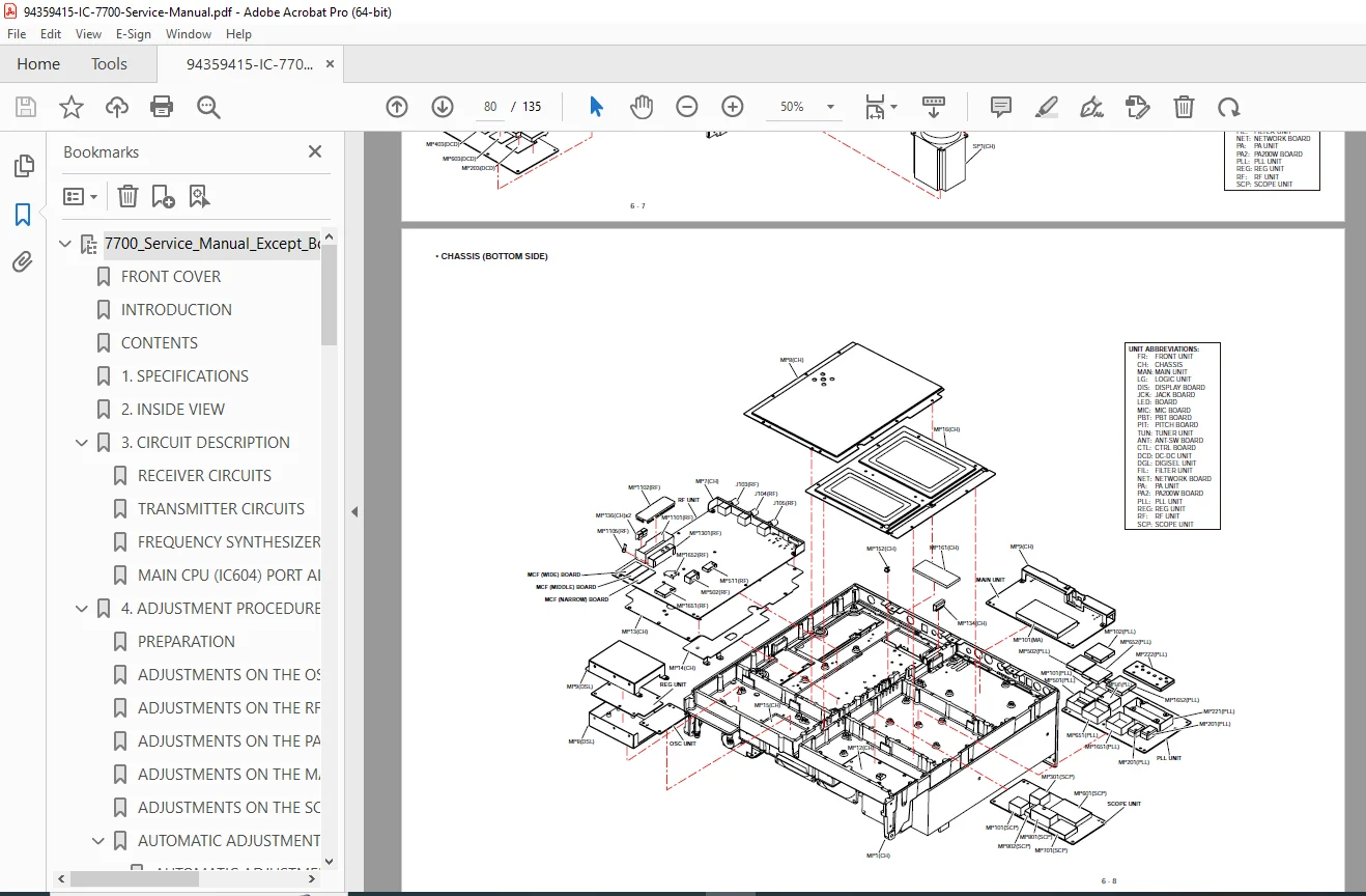
Exploded Diagrams:
- Main chassis assembly
- Front panel assembly
- Rear panel assembly
- Internal mounting structures
- Component installation sequences
SECTION 7: BOARD LAYOUTS
PCB Component Placement
Detailed board layouts for all units:
- Front Unit – Control interface board
- Logic Unit – Main CPU and logic circuits
- Main Unit – IF processing and control
- PLL Unit – Frequency synthesis
- OSC Unit – Reference oscillators
- ANT-SW Unit – Antenna switching
- DIGISEL Unit – Digital filter selection
- RF Unit – Receiver front-end
- Network Board – Interface circuits
- CTRL Board – Control distribution
- Filter Unit – Roofing filters
- PA200W Board – Final amplifier
- Scope Unit – Spectrum display
- DC-DC Unit – Power conversion
Layout Information:
- Component placement (top and bottom views)
- Test points identification
- Adjustment locations
- Connector pinouts
- Shield compartments
- Critical component locations
SECTION 8: GENERAL WIRING
Interconnection Diagrams
- Cable harness routing
- Inter-board connections
- Power distribution wiring
- Control signal paths
- Audio signal routing
- RF signal paths
- Antenna switching wiring
- External connector wiring
Wire Color Codes:
- Standardized color coding
- Signal identification
- Ground connections
- Power supply distribution
SECTION 9: BLOCK DIAGRAM
System-Level Diagrams
- Overall transceiver block diagram
- Signal flow visualization
- Receiver signal path
- Transmitter signal path
- Synthesizer architecture
- Control system hierarchy
- Power distribution
- Interface connections
- Functional block relationships
SECTION 10: SCHEMATIC DIAGRAMS
Complete Circuit Schematics
Detailed schematic diagrams for all units:
10-1: Front Unit
- Control panel circuitry
- Switch matrix
- Encoder circuits
- Display interface
10-2: Logic Unit
- Main CPU circuits
- Memory systems
- I/O interfaces
- Clock generation
- Reset circuits
10-8: Main Unit
- IF amplifier stages
- DSP circuits
- Audio processing
- Control interfaces
- Power regulation
10-12: PLL Unit
- Phase detector
- Loop filter
- VCO circuits
- Frequency dividers
- Reference circuits
10-13: OSC Unit
- High-stability reference oscillator
- Temperature compensation
- Buffer amplifiers
- Distribution circuits
10-16: ANT-SW Unit
- Antenna relay switching
- Band selection logic
- SWR sensing
- Protection circuits
10-16: DIGISEL Unit
- Digital filter control
- Mode selection logic
- Filter switching
10-17: RF Unit
- Preselector circuits
- RF amplifiers
- First mixer
- Attenuator circuits
- Band-pass filters
10-22: Network Board
- LAN interface
- USB interface
- Serial communications
- Remote control circuits
10-23: CTRL Board
- Control signal distribution
- Driver circuits
- Interface buffers
- Voltage regulation
10-24: Filter Unit
- Roofing filter circuits
- Filter selection relays
- Impedance matching
10-25: PA200W Board
- Driver stage
- Final amplifier (MOSFET power devices)
- Low-pass filters
- SWR bridge
- ALC feedback
- Bias circuits
- Temperature sensing
10-26: Scope Unit
- Spectrum analyzer circuits
- Display processing
- Waterfall generation
- FFT processing
10-29: DC-DC Unit
- Switching power supplies
- Voltage regulators
- Multiple voltage outputs
- Protection circuits
WHO NEEDS THIS IC-7700 ALIGNMENT PROCEDURES MANUAL?
This ham radio service manual is essential for:
- Amateur Radio Technicians – Professional ham radio repair shops
- Icom Authorized Service Centers – Factory-certified repair facilities
- Advanced Amateur Operators – Technically proficient hams performing own service
- RF Engineers – Understanding high-performance transceiver design
- Electronics Technicians – Expanding into amateur radio equipment service
- Technical Schools – Teaching radio communications repair
- Ham Radio Clubs – Club station equipment maintenance
KEY FEATURES OF THIS TRANSCEIVER TROUBLESHOOTING GUIDE
200W HF/50MHz TRANSCEIVER
Complete service documentation for Icom’s flagship amateur radio transceiver with full legal-limit output power across all HF amateur bands plus 6 meters.
DSP TECHNOLOGY COVERAGE
Detailed circuit descriptions and adjustment procedures for advanced Digital Signal Processing features including filters, noise reduction, and audio processing.
SPECTRUM SCOPE SERVICE
Complete service information for the integrated real-time spectrum display and waterfall functions.
FACTORY ALIGNMENT PROCEDURES
Precise adjustment procedures developed by Icom engineers ensuring optimal performance across all bands and modes.
COMPLETE SCHEMATIC DIAGRAMS
Full circuit schematics for every board and unit enabling component-level troubleshooting and repair.
MULTI-BAND COVERAGE
Service procedures for all amateur radio HF bands (160m through 10m) plus 6-meter band operation.
UNIVERSAL AC POWER SUPPLY
Built-in switching power supply accepting 85-265V AC for worldwide operation.
TECHNICAL SPECIFICATIONS COVERED
| Feature | Specification |
|---|---|
| Frequency Range | 0.03–60 MHz receive, 1.8–54 MHz transmit (amateur bands) |
| Output Power | 2–200W (SSB/CW/RTTY/PSK31/FM), 2–50W (AM) |
| Modes | USB, LSB, CW, RTTY, PSK31, AM, FM |
| Display | 7-inch TFT color LCD (800×480) |
| IF Frequencies | Multiple IF stages with DSP processing |
| Power Supply | 85–265V AC universal input |
| Antenna Ports | 4×SO-239 (50Ω) |
| Memory | 101 channels |
ADJUSTMENT EQUIPMENT REQUIRED
Test Equipment Specifications:
- RF signal generator (HF range)
- Spectrum analyzer
- RF power meter
- Frequency counter
- Audio signal generator
- Oscilloscope
- Digital multimeter
- Dummy load (50Ω, 200W minimum)
- Standard attenuators (50-60 dB)
- Deviation meter (for FM)
MAJOR FUNCTIONAL BLOCKS
Receiver System:
- Triple-conversion superheterodyne
- Digitally-controlled preselector
- Multiple roofing filter bandwidths
- DSP IF processing
- Digital noise reduction
- Automatic notch filter
- Twin PBT (Passband Tuning)
Transmitter System:
- High-level balanced modulation
- Speech processor with compression
- Multi-stage amplification
- MOSFET final amplifier
- Automatic band-switched low-pass filters
- SWR protection
- ALC system
Control System:
- Main CPU coordination
- Front panel interface
- Display management
- Remote control capability
- PC connectivity (USB, RS-232C, CI-V)
- Network interface option
ADJUSTMENT PROCEDURES COVERED
✓ Reference Oscillator – Frequency accuracy calibration
✓ Receiver Alignment – Preselector, IF stages, sensitivity
✓ Transmitter Adjustment – Output power, modulation, linearity
✓ PLL Synthesis – VCO calibration, lock range
✓ S-Meter Calibration – Accurate signal strength indication
✓ Power Output – Per-band calibration for 200W output
✓ ALC Calibration – Proper limiting and protection
✓ Spectrum Scope – Display accuracy and calibration
✓ Audio Systems – Microphone gain, speaker output
✓ Protection Circuits – SWR fold-back, over-temperature
CIRCUIT DESCRIPTION HIGHLIGHTS
Receiver Front-End:
- Preselector tuning (electronically switched)
- Low-noise RF amplifier
- Switchable attenuator (0, 6, 12, 18 dB)
- First mixer with excellent dynamic range
- Roofing filter selection (multiple bandwidths)
IF Processing:
- First IF at fixed frequency
- Second IF with DSP processing
- Digital filtering with selectable bandwidths
- Noise blanker and noise reduction
- Notch filter (manual and automatic)
Power Amplifier:
- High-efficiency MOSFET devices
- Temperature-compensated bias
- Automatic band switching
- Low-pass filter array
- SWR sensing and protection
- Harmonic suppression >50 dB
INTERFACE CAPABILITIES
External Connections:
- Four independent antenna ports
- Remote head operation capability
- External display output
- Computer control (multiple protocols)
- Audio input/output (ACC connectors)
- Linear amplifier keying
- Transverter interface
Digital Modes Support:
- RTTY operation
- PSK31 built-in
- USB sound card interface
- Digital mode optimized settings
SAFETY AND SERVICE NOTES
Critical Service Warnings:
- Never exceed specified DC voltage
- Do not expose to liquids
- Observe DC polarity
- Maximum 20 dBm (100 mW) input to antenna connector
- Use proper ESD precautions
- Never transmit into test equipment without attenuation
- Disconnect power before disassembly
- Use insulated adjustment tools
Parts Ordering Information:
- 10-digit Icom part numbers required
- Component name specification
- Equipment model and unit identification
- Quantity needed
- Authorized distributor addresses provided
REGIONAL VARIANTS COVERED
Manual includes specifications and adjustments for:
- USA Version – U.S. amateur band plan
- EUR Version – European specifications
- FRA Version – French market
- ITR Version – Italian market
- ESP Version – Spanish market
- UK Version – United Kingdom
- KOR Version – Korean market
PROFESSIONAL SERVICE CAPABILITIES
Component-Level Repair:
- Detailed schematics enable IC replacement
- Board layout shows all component locations
- Parts list provides exact part numbers
- Test point identification for troubleshooting
Performance Optimization:
- Factory alignment procedures restore original specifications
- Automatic adjustment routines verify proper operation
- Comprehensive test procedures ensure compliance
System Integration:
- Proper interconnection documentation
- Cable routing and shielding information
- Grounding and RF interference prevention
WHAT YOU’LL RECEIVE
Upon purchase, you receive instant download access to the complete 135-page Icom IC-7700 service manual in PDF format. This is the identical factory documentation used by Icom-authorized service centers worldwide, containing every schematic, adjustment procedure, parts list, and technical specification needed for professional-level amateur radio transceiver service and repair.
Don’t risk improper adjustments or incomplete service documentation—get the official factory manual with complete schematics, precision alignment procedures, and DSP circuit descriptions trusted by professional radio technicians worldwide. Download instantly and service your IC-7700 flagship transceiver with complete factory-level confidence today!