
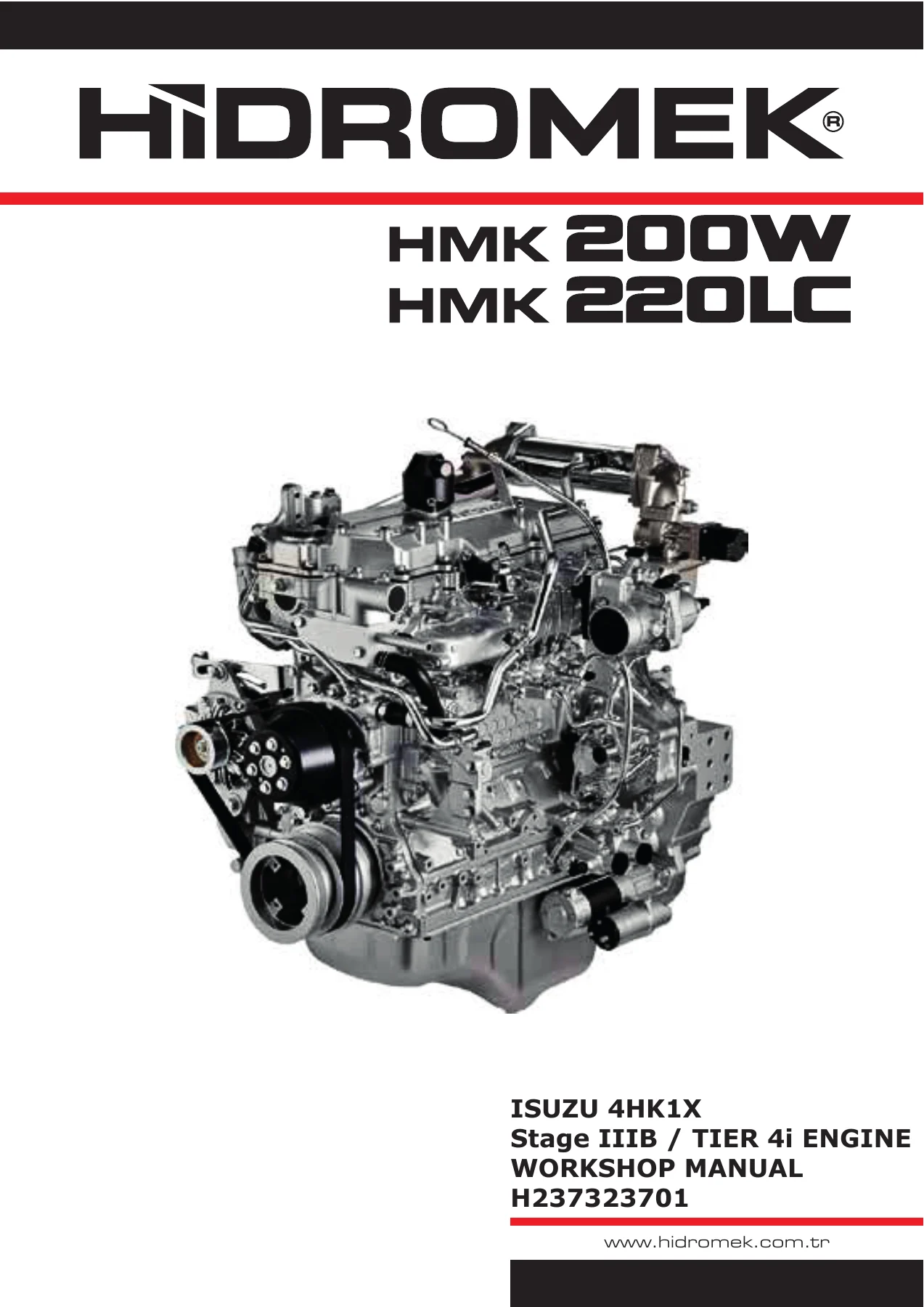
Isuzu 4HK1X Stage IIIB Tier 4i Engine Workshop Manual – Hidromek HMK 200W HMK 220LC PDF (H237323701)
Original price was: $65.95.$40.95Current price is: $40.95.
Complete Isuzu 4HK1X Stage IIIB / Tier 4i engine workshop manual for the Hidromek HMK 200W and HMK 220LC, published under document number H237323701. Roughly 939 pages of mechanical, fuel, lubrication, cooling, electrical and inlet/exhaust procedures, with torque tables, ECM pin data and full DTC diagnosis. Instant PDF download.
Description
Isuzu 4HK1X Stage IIIB / Tier 4i Engine Workshop Manual for Hidromek HMK 200W and HMK 220LC
The Isuzu 4HK1X Stage IIIB / Tier 4i Engine Workshop Manual is the full service documentation for the 5.193 L four-cylinder 4HK1X diesel installed in the Hidromek HMK 200W and Hidromek HMK 220LC. Issued under document number H237323701 and running to roughly 939 pages, it covers the engine end to end – cylinder head and block, common rail fuel system, gear-type oil pump, water-cooled oil cooler, twin-thermostat cooling circuit, VGS turbocharger, cooled EGR, DPD aftertreatment and the complete electronic control system.
This is not a generic engine overview. It is the workshop manual written for the technician who has to pull a cylinder head, measure compression, set valve clearance at 0.4 mm, chase a P0088 high rail pressure fault, test an injector charge circuit or re-time a supply pump – and who needs the manufacturer’s own figures in hand while doing it. Every section follows the same discipline: what the system does, how to test it, what the readings should be, and how to strip and rebuild it correctly.
File Details
- Manual type: Engine workshop / service manual
- Engine covered: Isuzu 4HK1X, Stage IIIB / Tier 4i
- Machines covered: Hidromek HMK 200W, Hidromek HMK 220LC
- Document number: H237323701
- Language: English
- Page count: Approximately 939 pages
- File format: PDF
Chapters Covered
- 01 Engine General Information
- 02 Mechanical
- 03 Engine Lubrication System
- 04 Engine Cooling System
- 05 Engine Fuel System
- 06 Engine Electrical System
- 07 Engine Inlet and Exhaust System
01 – Engine General Information
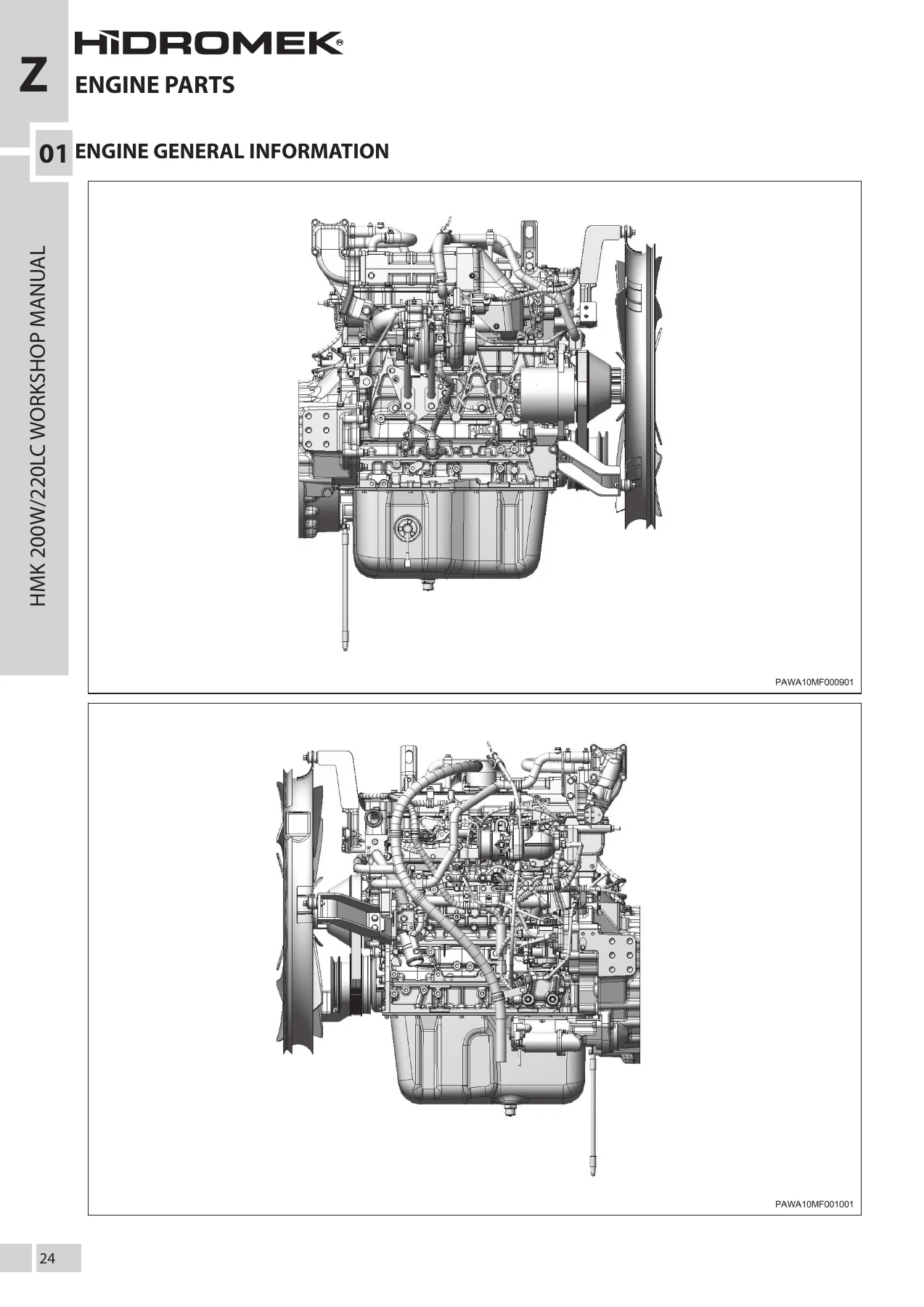
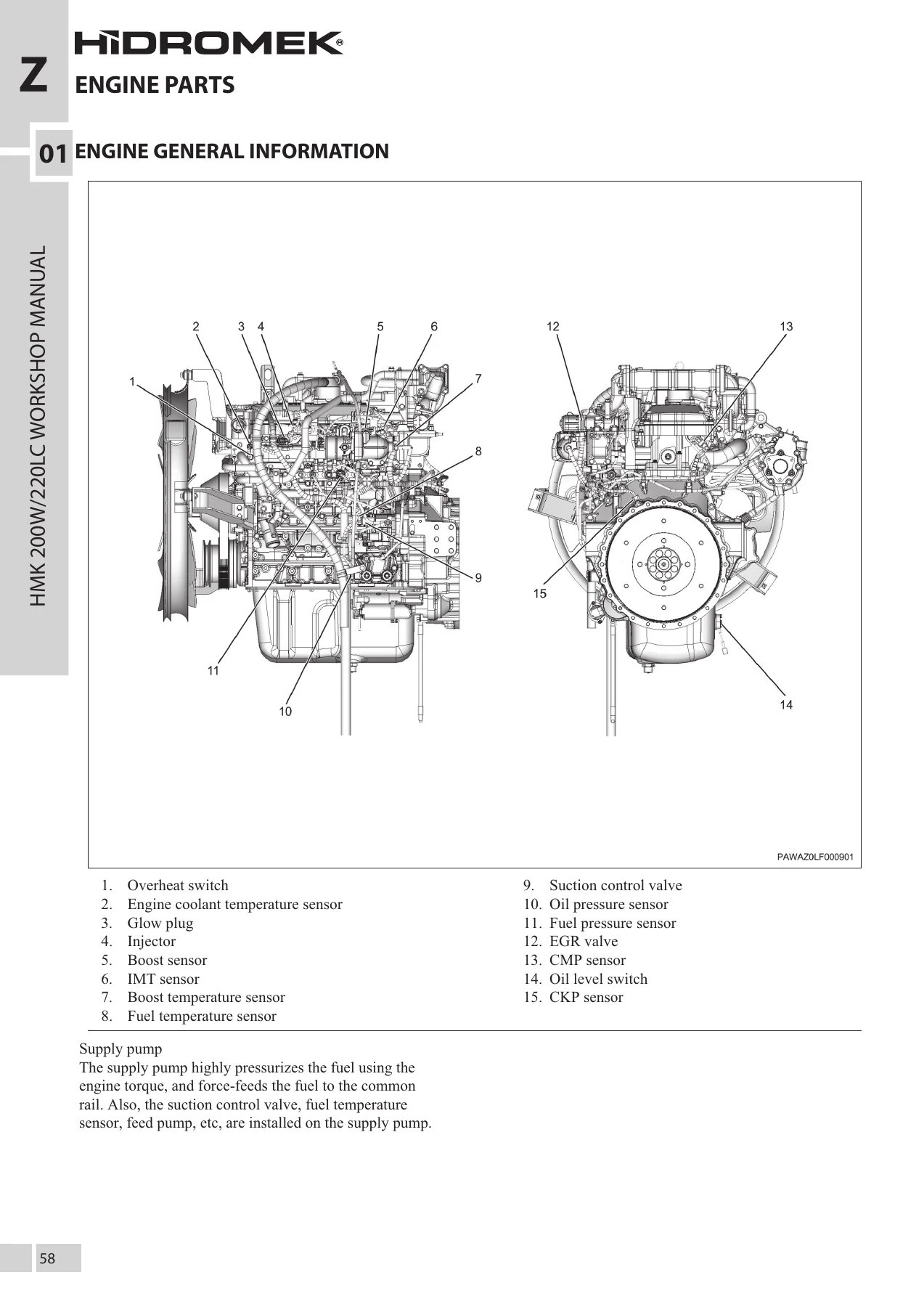
Far more than a safety page. This chapter carries the repair-work safety rules, the replacement-parts policy, the complete symbol key used throughout the book, and the standard bolt and nut tightening torque tables broken down by strength category (4.8 / 4T, 7T, 8.8, 9.8 / 9T) and by head shape, in metric and imperial units. It explains plastigage measurement for connecting rod bearings and crankshaft journals, liquid gasket selection and bead widths, thread locking adhesives, terminology and the abbreviation list. The primary engine specifications for the 4HK1 sit here, followed by maintenance precautions, the ECM power distribution diagram, the full ECM pin assignment tables and the ECM pin-by-pin connection list, then the whole trouble diagnosis framework: symptom-based diagnosis, DTC reading with a diagnostic light, clearing procedures and reference data values.
02 – Mechanical
The largest single block of the manual. It deals with the hard mechanical work – cylinder block, dry cylinder liners and their identification stamps, pistons and rings, the cast iron four-valve-per-cylinder cylinder head, crankshaft and journal grading, connecting rod cap bolts, bearing selection and clearance checks, camshaft and valve train, valve clearance setting and compression pressure testing. Assembly torques, angle-tightening methods and service limits are given as you go, so a rebuild can be done to specification rather than to feel.
03 – Engine Lubrication System
Covers the pressure-feed lubrication circuit, the gear-type oil pump and its drive, the full-flow / partial-flow combined cartridge oil filter, the built-in water-cooled oil cooler and the piston coolant oil jets. The chapter opens with a complete lubrication flow schematic – delivery valve, relief valve, oil cooler, thermo valve, oil gallery, check valve and the oil pressure switch – then moves to component inspection, oil pressure testing and lubrication system fault checking.
04 – Engine Cooling System
The forced-circulation cooling circuit with its centrifugal impeller water pump, twin wax-pellet thermostats (bottom bypass at 82 C and inline at 85 C), radiator, reserve tank, EGR cooler, turbocharger coolant feed and heater circuit. Cooling system specifications, thermostat opening and full-open temperatures, coolant capacity, the full system diagram and the cooling system check procedure are all included, along with water pump inspection and seal unit details.
05 – Engine Fuel System
The common rail heart of the 4HK1X. Supply pump with suction control valve, fuel temperature sensor and feed pump; the common rail with its fuel pressure sensor and pressure limiter; and the seven-hole solenoid injectors with their ID codes and QR data. The chapter covers the fuel filter with sedimenter, the electromagnetic pump and pre-filter layout, air removal from the fuel system, fuel filter clog warning and engine speed restriction logic, plus the high-precision handling rules that apply to every component in the high-pressure circuit.
06 – Engine Electrical System
Charging, starting and preheat, plus the complete engine control architecture. The brushless 24 V / 50 A generator, the 5.0 kW reduction starter with magnetic shift and one-way clutch, and the QOS glow plug system are all described with internal cutaways. Then the engine control system itself: basic fuel injection quantity calculation, correction maps, injection pressure control, injection timing and rate control, maximum fuel injection limitation, high altitude correction, overheat fuel restriction, emergency stop logic, the EGR control strategy, turbocharger control through the turbo control unit, mode map switch and idling control behaviour, and CAN communication layout. Wiring diagram conventions, connector information, connector location diagrams and terminal names close the chapter.
07 – Engine Inlet and Exhaust System
Intake and exhaust routing, the VGS turbocharger with its variable nozzle, control rod, turbo actuator and position feedback, the intake throttle valve, the EGR valve and cooler circuit, the DPD assembly with its oxidation catalyst and filter, exhaust gas temperature sensors 1 and 2, and the exhaust differential pressure sensor. The DPD material – regeneration logic, accumulation status, manual and automatic regeneration, ash removal and post-regeneration checks – is covered in practical, procedural detail.
Diagnostic Trouble Code Coverage
The engine management section works through the 4HK1X diagnostic trouble codes one at a time, each with a description of the circuit, the exact conditions that set the code, and the action the ECM takes when it sets. The list runs across the whole engine – camshaft and crankshaft correlation, fuel rail pressure too low and too high, suction control valve circuit low and high, fuel system leak detection, mass air flow circuit low and high, intake air and coolant temperature circuits, throttle position sensor circuits, fuel temperature sensor circuits, rail pressure sensor circuits, injector circuits for all four cylinders, coolant over-temperature, engine overspeed, turbocharger overboost and boost sensor circuits, crank and cam position sensor circuits, EGR control range and EGR position sensor circuits, intake manifold temperature circuits, catalyst temperature sensor circuits for both sensors, oil pressure sensor circuits, system voltage, ECM internal processor and memory faults, A/D processing, throttle actuator control range, sensor reference voltage circuits, MIL control circuit, ECM main relay circuits, injector positive voltage control groups 1 and 2, fuel filter pressure sensor circuits, EGR closed position performance, PM over-accumulation, DPD insufficient regeneration, DPD restriction, DPD differential pressure sensor circuits and the accelerator pedal position sensor circuits including the P2138 correlation fault. Each entry tells you what to measure and what the reading should be, which turns a fault code into an actual repair path.
Specifications, Torque Values and Measurement Data
Hard numbers are spread through the manual rather than hidden in an appendix. Standard bolt torque tables cover M6 through M24 in both fine and coarse thread, across four strength categories, with hex and flange head variants. Flare nut and tapered thread torque values for fuel and hydraulic connections are tabulated with the correct widths across flats. Engine data includes bore and stroke of 115 mm x 125 mm, 5.193 L displacement, 17.5 compression ratio, compression pressure of 3.23 MPa at 200 r/min, 800 r/min idle, valve clearance of 0.4 mm intake and exhaust when cool, and a 1-3-4-2 injection order. Lubrication oil quantity of 20 to 27 L, coolant capacity of 14.5 L, injector nozzle bore of 0.14 mm across seven holes, and glow plug rating of 23 V / 3.5 A are all listed. Compression testing, oil pressure testing at 550 kPa minimum at 2000 r/min, and DPD differential pressure checks with their specified values give you real pass/fail criteria instead of guesswork.
What This Isuzu 4HK1X Workshop Manual Lets You Do
With this manual on the bench you can carry out a full engine overhaul on a Hidromek HMK 200W or HMK 220LC, diagnose a no-start or a derate condition using the factory DTC logic, replace and code injectors, service the common rail and supply pump correctly, rebuild or replace the turbocharger, repair the EGR and DPD systems, and verify your work against the manufacturer’s own pressures, torques and clearances. It also supports the jobs that go wrong when the numbers are guessed: setting valve clearance, selecting the right bearing grade, torquing angle-tightened cylinder head and connecting rod bolts, and bleeding a high-pressure fuel system without introducing contamination.
Heavy equipment engines are unforgiving of approximate work. A rail pressure fault misdiagnosed as a pump failure, an injector installed without its ID code written to the ECM, or a cylinder head bolt torqued to the wrong figure can each turn a routine repair into a repeat failure and lost working hours. Having the actual procedure, the actual torque and the actual test value in front of you is the difference between a repair that holds and one that comes back.
IMAGES PREVIEW
Delivery is instant. The manual arrives as a downloadable PDF the moment payment clears – no shipping, no waiting for a parcel, no customs. Open it on a laptop in the workshop, a tablet at the machine, or a phone on site, and print whichever pages you need for the job in front of you. Keep a clean copy on file and a dirty copy on the bench.

Reviews
There are no reviews yet.