
Isuzu F&G-Series 6SD1-TC Engine Emission Workshop Manual – 6SD1-WE-0115HK
Original price was: $39.95.$23.95Current price is: $23.95.
Isuzu F&G-Series 6SD1-TC Engine Emission Workshop Manual — 6SD1-WE-0115HK. 383-page PDF covering the IE common-rail system, diagnostic trouble codes, wiring checks, and repair procedures for 6SD1-TC engines.
Description
Isuzu F&G-Series 6SD1-TC Engine Emission Workshop Manual — 6SD1-WE-0115HK
The Isuzu F&G-Series 6SD1-TC Engine Emission Workshop Manual is the dedicated service guide for the IE System — Isuzu’s electronically controlled common-rail fuel injection system — as installed in the 6SD1-TC engine. Published under document number 6SD1-WE-0115HK as a first edition in December 2001, this 383-page workshop manual gives technicians the complete diagnostic and repair framework for the engine emission control systems used across F&G-Series trucks in Hong Kong. Whether you are troubleshooting a diagnostic trouble code, checking sensor circuits, or performing accelerator learning, this manual provides the step-by-step procedures, wiring diagrams, and specification data needed to get the job done accurately.
File Details
- Manual Type: Engine Emission Workshop Manual
- Brand: Isuzu
- Series: F&G-Series
- Engine: 6SD1-TC
- Document Number: 6SD1-WE-0115HK
- Edition: First Edition, December 2001
- Language: English
- Page Count: 383
- File Format: PDF
- Publisher: Isuzu Motors Limited, International Service Department
Chapters Covered
The Isuzu 6SD1-TC engine emission workshop manual is organised into eight chapters that move from system overview through diagnosis, repair, and wiring verification:
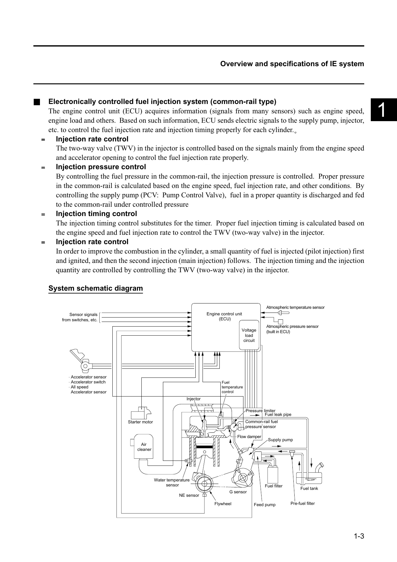
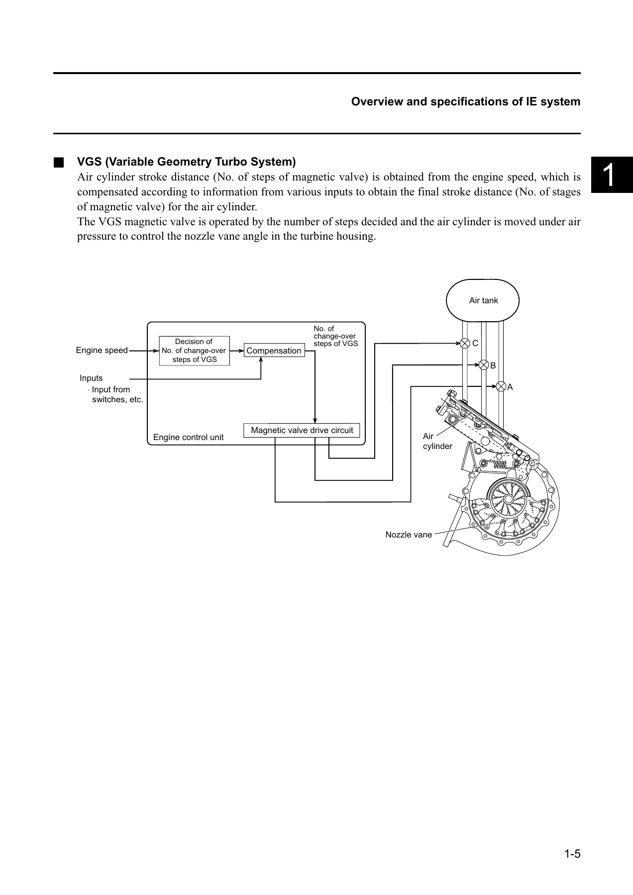
- Chapter 1 — Overview of IE System: IE system specifications, electronically controlled fuel injection system (common-rail type) including injection rate control, injection pressure control, injection timing control, and pilot injection; VGS (Variable Geometry Turbo System); idle control switch; output of idle position signal to brake intensive control unit; output of engine rotations to tachometer; engine control unit external view and input/output list; accelerator learning object and procedure; Q adjustment data.
- Chapter 2 — Failure Diagnosis: Self-diagnosis of the IE system; checking diagnostic trouble codes via SERVICE ENGINE SOON lamp and multi-warning; erasing codes with the memory clear switch; Tech 2 operation manual; vehicle diagnostic procedure; complete diagnostic trouble codes list with failure contents, judge times, and backup control data.
- Chapter 3 — Functional Diagnosis: Checking the SERVICE ENGINE SOON lamp lighting circuit; checking the lamp flickering control system; checking the Tech II; checking the engine starting system; checking the power supply circuit; checking the starting system; checking the fuel system; checking the intake system; checking the exhaust system; checking the parking switch; idling speed adjustment procedures.
- Chapter 4 — Checking Procedure for Each Diagnostic Trouble Code: Detailed troubleshooting for DTCs 14, 15, 22, 23, 24, 25, 32, 33, 35, 42, 65, 71, 115, 118, 151, 158, 159, 211, 217, 218, 226, 227, 241, 242, 245, 247, 248, 271, 272, 273, 274, 275, 276, 411, 412, 415, 416, 417, 418, 421, 518, and 543 — covering G sensor, NE sensor, atmospheric temperature sensor, water temperature sensor, accelerator sensor, vehicle speed sensor, boost sensor, CPU monitoring IC, A/D conversion, high/low boost, atmospheric pressure sensor, fuel pressure sensor, common-rail pressure, TWV power systems, fuel temperature sensor, PCV systems, supply pump, accelerator switch, injector drive systems, magnetic valves, main relay, starter switch, fail-safe relay, PCV relay, EOL data, and excessive high revolution.
- Chapter 5 — Checking Method for Symptom: Engine stall; engine hunting and rough idle; lack of output power, insufficient blow up, pulsating combustion; white smoke (large); black smoke (large).
- Chapter 6 — Wiring Check: Wire identification, wiring specifications, fuse and relay information, connector and harness handling; vehicle wiring harness layout; wiring checks for engine control unit power source and GND, NE/G/fuel pressure sensor circuits, boost and all-speed accelerator sensor circuits, accelerator sensor and switch circuits, temperature sensor circuits, PCV and PCV relay circuits, injector (TWV) circuits, magnetic valve and fail-safe relay circuits, vehicle speed sensor circuit, starting circuit, meter circuit, self-diagnosis circuit, neutral circuit, clutch switch circuit, brake switch circuit, reverse circuit, idling control switch circuits, and exhaust brake circuit.
- Chapter 7 — How to Use IE System Inspection Tools: Tech II operation; switch input inspection; special functions including fuel pressure control, injection timing, cylinder power balance, pilot injection stop, injection stop, RPM control, exhaust brake control, and solenoid valve testing; programming; accelerator learning procedure; upload and download fuel delivery rate data.
- Chapter 8 — Others: Inspection item chart for IE system condition; abbreviation list; programming and upload/download fuel delivery rate data procedures.
What This Manual Provides
This Isuzu F&G-Series workshop manual goes far beyond a basic service guide. The core of the document is the IE System — a common-rail electronically controlled fuel injection system that manages injection rate, injection pressure, injection timing, and pilot injection based on inputs from a wide network of sensors. The manual explains how the engine control unit (ECU) acquires information from the NE sensor, G sensor, fuel pressure sensor, boost sensor, accelerator sensor, water temperature sensor, fuel temperature sensor, atmospheric temperature sensor, and atmospheric pressure sensor, and how it uses that data to control the supply pump, injectors, and other actuators.
For technicians, the most valuable sections are the diagnostic trouble code procedures in Chapter 4. Each DTC gets its own multi-step troubleshooting flow, complete with circuit diagrams, connector pin references, resistance values, voltage checks, and corrective actions. The manual covers both the diagnostic side — how to read codes, interpret them, and trace faults — and the repair side, with procedures for replacing sensors, injectors, supply pumps, PCV valves, magnetic valves, and relays.
The wiring check chapter is equally thorough, providing circuit diagrams for every major subsystem. Each diagram shows connector pin numbers, wire colours and diameters, and the routing between the engine control unit, sensors, actuators, and other control units. This makes it possible to trace faults through the entire harness, not just at the component level.
Engine Control Unit and IE System Coverage
The manual covers the full IE system architecture on the 6SD1-TC engine, including:
- Electronically controlled fuel injection (common-rail type): Injection rate control via the two-way valve (TWV) in each injector, injection pressure control through the common-rail and supply pump PCV, injection timing control, and pilot injection for improved combustion.
- VGS (Variable Geometry Turbo System): Air cylinder stroke control via magnetic valves, nozzle vane angle adjustment, and the magnetic valve drive circuit.
- EGR (Exhaust Gas Recirculation): System overview and control.
- Idle control: Idle control switch operation, idle speed adjustment, and the idle control selector switch for AUTO/MANUAL mode.
- PTO control: Power take-off governor property change-over and accelerator change-over.
- Communication functions: Interfaces with the brake integrated control unit, ASR control unit, ECOGIT control unit, semi-auto clutch control unit, A/T control unit, and simplified fuel cost/vehicle weight indicator control unit.
- Auto cruise control and auxiliary brake-linked auto cruise control.
- Self-diagnosis function with SERVICE ENGINE SOON lamp and multi-warning indication.
Diagnostic Trouble Code Coverage
The Isuzu 6SD1-TC engine emission manual provides troubleshooting procedures for an extensive list of diagnostic trouble codes, including sensor system faults (G sensor, NE sensor, atmospheric temperature, water temperature, accelerator, vehicle speed, boost, atmospheric pressure, fuel pressure, fuel temperature), actuator and drive system faults (injector drive systems for all six cylinders, TWV power systems, PCV systems, magnetic valves A/B/C, main relay, starter switch, fail-safe relay, PCV relay), and system-level faults (CPU monitoring IC, A/D conversion, high/low boost, common-rail pressure, supply pump pressure feed, EOL data error, excessive high revolution). Each procedure includes possible causes, diagnostic conditions, warning lamp behaviour, and a step-by-step checking and corrective action table.
Why This Manual Matters
Common-rail fuel injection systems are complex, and the IE System on the Isuzu 6SD1-TC engine is no exception. Without the correct diagnostic procedures, technicians risk misdiagnosing faults, replacing parts unnecessarily, or causing further damage. This manual provides the exact resistance values, voltage ranges, pin assignments, and circuit paths needed to diagnose faults accurately the first time. The step-by-step flow charts in Chapter 4 are particularly valuable — they guide you through each check in the correct order, so you can isolate the faulty component without guesswork.
The wiring diagrams in Chapter 6 are essential for tracing intermittent faults, short circuits, and open circuits. Each diagram shows the complete circuit path from the ECU through the harness to the sensor or actuator, including connector numbers, pin positions, and wire colours. This level of detail is what separates a professional repair from a parts-swapping exercise.
Who This Manual Is For
This Isuzu F&G-Series 6SD1-TC Engine Emission Workshop Manual is written for professional diesel technicians, fleet maintenance workshops, and technically minded owners who need to diagnose and repair the IE system on these engines. It assumes a working knowledge of diesel engine fundamentals and electrical diagnostics, but the step-by-step procedures are detailed enough to guide you through even complex diagnostic sequences.
The manual is also useful for anyone performing routine maintenance on the engine emission system, such as accelerator learning after replacing the engine control unit or accelerator sensor, checking and clearing diagnostic trouble codes, and verifying sensor operation.
Get Instant Access
IMAGES PREVIEW
The Isuzu F&G-Series 6SD1-TC Engine Emission Workshop Manual (6SD1-WE-0115HK) is delivered as an instant PDF download. There is no shipping, no waiting, and no physical media to lose. The file can be viewed on any device — laptop, tablet, or smartphone — and printed pages can be taken directly to the workshop. Whether you are diagnosing a fault code, tracing a wiring issue, or performing a repair procedure, this manual puts the information you need at your fingertips.

Reviews
There are no reviews yet.