Isuzu Hitachi 4HK1 6HK1 Engine Workshop Manual – PDF DOWNLOAD
$36.95
Isuzu Hitachi 4HK1 6HK1 Engine Workshop Manual – PDF DOWNLOAD
Description
Isuzu Hitachi 4HK1 6HK1 Engine Workshop Manual – PDF DOWNLOAD
FILE DETAILS:
Isuzu Hitachi 4HK1 6HK1 Engine Workshop Manual – PDF DOWNLOAD
Language : English
Pages : 1310
Downloadable : Yes
File Type : PDF
IMAGES PREVIEW OF THE MANUAL:
TABLE OF CONTENTS:
Isuzu Hitachi 4HK1 6HK1 Engine Workshop Manual – PDF DOWNLOAD
4HK1_WM_1 1
Engine Manual(1/2) 1
Introduction 2
General Contents 4
Control System 6
Engine Control (Electronic control fuel injection system (Common rail type)) 6
How to use this manual 8
Table of abbreviation 9
List of parts according to engine control specifications 10
About colors of wirings 11
About wiring diagrams 12
How to read trouble diagnosis section 13
Precautions on Service Work 15
Procedure of trouble diagnosis 16
Information: 17
Interview 18
Pre-inspection 20
Information: 20
Trouble Diagnosis 20
Description of terms 20
How to read DTC 21
Confirmation after repair 23
List of final check items 23
How to clear DTC 24
Trouble diagnosis with scan tool 25
About scan tool display 26
How to use trouble diagnosis-related tool 30
How to use Tech2 30
Components of Tech2 30
Each part of Tech2 31
Precautions on handling Tech2 32
Power supply 34
Check items before use 35
How to connect Tech2 35
Operation procedure 36
List of functions of Tech2 38
Diagnostic procedure 39
DTC application menu display screen 41
Data Display 42
Snapshot 43
Actuator test 47
Injector balance test 48
View captured data 50
Tool options 52
Rewrite setting of Q adjust data by Tech2 53
Injector ID code (No 1 cylinder – No 6 cylinder) registration setting using Tech2 60
ID code upload (Tech2) 68
ID code download (Tech2) 70
How to use TIS 2000 73
TIS 2000 installation procedure 73
How to display snapshot 75
Software download 80
How to Inspect Injector 83
How to use injector checker 83
Components of injector checker 83
Method to identify using non-contact infrared thermometer 87
How to use flash tool 89
Refer to related documents 89
How to use breaker box 90
Breaker box inspection procedure 90
How to connect breaker box 90
Example of use for breaker box 91
Engine Control System 93
Description of function and operation 93
About engine control (common rail) system 93
System control schematic diagram 93
Table of Input/Output 95
Electronic control fuel injection system (Common rail type) 95
System schematic diagram 97
Fuel system 98
EGR (Exhaust gas recirculation) 98
Idling control 100
Speed limit control 100
Engine speed output to tachometer 101
Preheating control 102
Engine Control Module (ECM) 102
Engine component location diagram 104
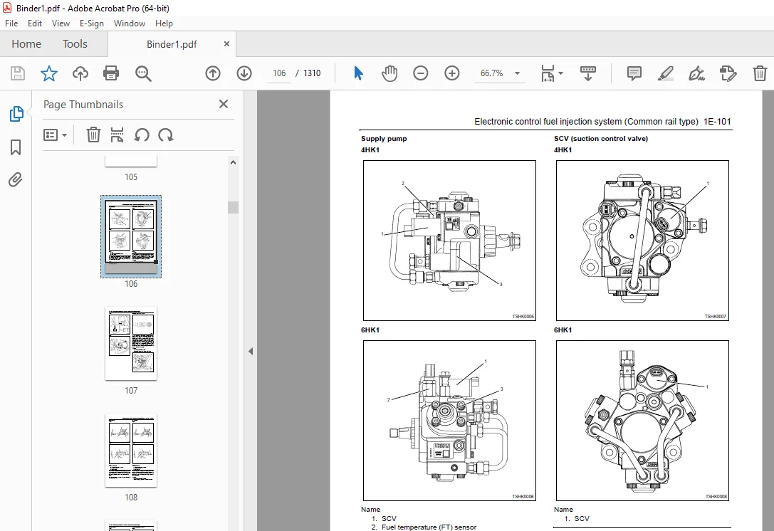
Supply pump 106
SCV (suction control valve) 106
Fuel temperature (FT) sensor 107
Common rail 108
Flow damper 108
Pressure limiter 109
Common rail pressure sensor 109
Injector 110
Engine coolant temperature (ECT) sensor 110
Crankshaft position (CKP) sensor 111
Camshaft position (CMP) sensor 112
Engine oil pressure sensor 113
Accelerator position (AP) sensor 113
Intake air temperature (IAT) sensor 114
EGR position sensor 114
Boost pressure sensor 115
Boost temperature sensor 115
Diagnosis lamp 116
DLC (data link connector) 116
Diagnostic switch 116
Memory clear switch 116
Mode selector switch (1, 2, 3) 116
Wiring diagram of engine control module (ECM) 117
Pin arrangement of engine control module (ECM) 119
Circuit diagram 123
Main relay circuit 123
Starter for ECM control, glow circuit 124
Starter for safety relay, glow circuit 126
CAN, GND, DLC circuits 128
Indicator lamp, tachometer circuit 129
Injector circuit 130
SCV circuit 132
CKP sensor, vehicle speed sensor, fuel temperature sensor, engine coolant temperature sensor, engine oil pressure sensor circuit 133
Boost temperature sensor, boost pressure sensor circuit 134
CMP sensor, common rail pressure sensor, EGR circuit 135
Accelerator position sensor, barometric pressure sensor, intake air temperature sensor circuit 136
Idling selector switch, idle up switch, idle down switch, mode map switch circuit 137
Memory clear switch, engine stop switch circuit 138
Engine harness location 139
H94/H95 connector 150
Connector list 151
List of function checks 154
OBD system check 155
Diagnosis lamp illumination circuit system check 157
Diagnosis lamp blinking circuit system check 159
Scan tool power supply circuit system check 162
Scan tool communication circuit system check 164
Starting circuit system check 167
Starting system check 173
Fuel system check 176
Intake system check 178
Exhaust system check 179
EGR control system check 180
QOS system check 183
List of diagnostic trouble code 188
DTC: P0087 (Flash code 227) Common rail low pressure fault (No pressure feed in supply pump) 212
DTC: P0088 (Flash code 118) Common rail pressure is abnormally high (1st or 2nd stage) 220
DTC: P0089 (Flash code 151) Common rail pressure fault (Excessive pressure feed in supply pump) 225
DTC: P0090 (Flash code 247) SCV drive system open circuit, +B short or ground short 230
DTC: P0107 (Flash code 71) Barometric pressure sensor circuit input is low (open circuit or ground short) 236
DTC: P0108 (Flash code 71) Barometric pressure sensor circuit input is high (+5 V short) 243
DTC: P0112 (Flash code 22) Intake air temperature sensor fault (low voltage fault, GND short, short circuit) 250
DTC: P0113 (Flash code 22) Intake air temperature sensor fault (high voltage fault, open circuit or short to power supply circuit) 256
DTC: P0117 (Flash code 23) Engine coolant temperature sensor fault (low voltage fault, GND short, short circuit) 264
DTC: P0118 (Flash code 23) Engine coolant temperature sensor input is high (open circuit or short to power supply) 271
DTC: P0182 (Flash code 211) Fuel temperature sensor fault (low voltage fault, GND short) 279
DTC: P0183 (Flash code 211) Fuel temperature sensor fault (high voltage fault, open circuit or short to power supply circuit) 285
DTC: P0192 (Flash code 245) Common rail pressure sensor fault (low voltage fault, short circuit) 293
DTC: P0193 (Flash code 245) Common rail pressure sensor fault (high voltage fault) 299
DTC: P0201 (Flash code 271) Open circuit in injection nozzle #1 drive system 306
DTC: P0202 (Flash code 272) Open circuit in injection nozzle #2 drive system 313
DTC: P0203 (Flash code 273) Open circuit in injection nozzle #3 drive system 320
DTC: P0204 (Flash code 274) Open circuit in injection nozzle #4 drive system 327
DTC: P0205 (Flash code 275) Open circuit in injection nozzle #5 drive system 334
DTC: P0206 (Flash code 276) Open circuit in injection nozzle #6 drive system 339
DTC: P0219 (Flash code 543) Overrun 344
DTC: P0237 (Flash code 32) Boost sensor pressure fault (low voltage fault, open circuit) 346
DTC: P0238 (Flash code 32) Boost pressure sensor fault (high voltage fault, short to power supply circuit, ground open circuit) 353
DTC: P0335 (Flash code 15) Crank sensor fault (no signal) 360
DTC: P0336 (Flash code 15) Crank sensor fault (signal fault) 367
DTC: P0340 (Flash code 14) Cam sensor fault (no signal) 373
DTC: P0341 (Flash code 14) Cam sensor fault (signal fault) 380
DTC: P0380 (Flash code 66) Glow relay circuit fault 386
DTC: P0381 (Flash code 67) Glow plug lamp circuit fault 391
DTC: P0487 (Flash code 44) EGR position sensor fault 396
DTC: P0488 (Flash code 45) EGR valve control fault 402
DTC: P0522 (Flash code 294) Engine oil pressure sensor fault (low voltage fault, open circuit, ground short) 408
DTC: P0523 (Flash code 295) Engine oil pressure sensor fault (high voltage fault, short to power supply, ground short) 414
DTC: P0601 (Flash code 53) ROM fault 422
DTC: P0603 (Flash code 54) EEPROM fault 424
DTC: P0606 (Flash code 51/52) CPU fault 426
DTC: P0611 (Flash code 34) Charge circuit fault (bank 1) 428
DTC: P0612 (Flash code 34) Charge circuit fault (bank 2) 431
DTC: P0650 (Flash code 77) Diagnosis lamp circuit fault 434
DTC: P1093 (Flash code 227) No pump pressure feed 439
DTC: P1095 (Flash code 225) Pressure limiter open 448
DTC: P1112 (Flash code 295) Boost temperature sensor fault (low voltage fault, ground short) 457
DTC: P1113 (Flash code 295) Boost temperature sensor fault (high voltage fault, open circuit, short to power supply circuit) 465
DTC: P1173 (Flash code 542) Overheat 471
DTC: P1225 (Flash code 31) Idle UP/DOWN switch fault 477
DTC: P1261 (Flash code 158) Injection nozzle common 1 drive system fault 481
DTC: P1262 (Flash code 159) Injection nozzle common 2 drive system fault 492
DTC: P1271 (Flash code 24) Accelerator sensor 1-2 comparison fault 503
DTC: P1277 (Flash code 24) Accelerator sensor 1 fault (low voltage fault) 509
DTC: P1278 (Flash code 24) Accelerator sensor 1 fault (high voltage fault) 514
DTC: P1282 (Flash code 24) Accelerator sensor 2 fault (low voltage fault) 519
DTC: P1283 (Flash code 24) Accelerator sensor 2 fault (high voltage fault) 524
DTC: P1345 (Flash code 16) Cam sensor out of phase 529
DTC: P1625 (Flash code 416) Main relay fault 534
DTC: P1630 (Flash code 36) A/D conversion fault 541
DTC: P1631 (Flash code 55) Voltage fault in 5-V power supply 1 543
DTC: P1632 (Flash code 55) Voltage fault in 5-V power supply 2 546
DTC: P1633 (Flash code 55) Voltage fault in 5-V power supply 3 549
DTC: P1634 (Flash code 55) Voltage fault in 5-V power supply 4 552
DTC: P1635 (Flash code 55) Voltage fault in 5-V power supply 5 555
DTC: U2104 (Flash code 84) CAN Bus fault 558
DTC: U2106 (Flash code 85) CAN timeout fault 563
List of trouble symptom 568
Engine start failure 569
Engine stall 573
Engine hunting, rough idling 577
Engine output shortage 581
Exhaust gas contains a lot of white smoke 586
Exhaust gas contains a lot of black smoke 589
Noise 592
Fuel consumption deteriorates 594
Oil consumption deteriorates 597
Special Tool 599
Difference by each machine manufacturer 600
Hitachi Construction Machinery Co , Ltd 600
About wiring diagrams 603
Tech2 reference value 609
Engine Manual(2/2) 616
Introduction 617
General Contents 618
Disassemble and Assemble Engine 619
General Information 619
General Information 622
Service Precautions 622
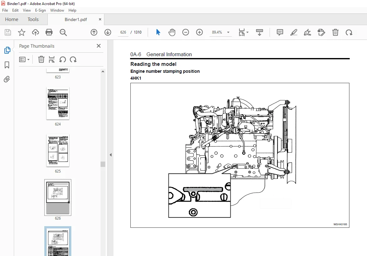
Reading the model 626
General information 627
ENGINE MECHANICAL (4HK1, 6HK1) 635
ISUZU DIESEL ENGINE (4HK1, 6HK1) 637
Precautions on Service Work 637
Main Data and Specifications 645
Cylinder Head Cover 648
Components 648
Removal 649
Installation 650
Torque Specifications 652
Inlet Cover 654
Components 654
Removal 655
Installation 656
Torque Specifications 658
Turbocharger and Exhaust Manifold 659
Components 659
Removal 660
Inspection 661
Installation 662
Torque Specifications 666
Timing Gear Train 669
Components 669
Removal 670
Inspection 672
Installation 674
Torque Specifications 685
Special Tool 686
Rocker Arm Shaft ASM 687
Components 687
Removal 687
Disassembly 688
Reassembly 690
Installation 691
Torque Specifications 693
Camshaft ASM 694
Components 694
Removal 695
Disassembly 696
Reassembly 698
Fixing torque 700
Special Tool 700
Installation 701
Torque Specifications 703
Valve Stem Seal, Valve Spring 704
Components 704
Removal 704
Inspection 705
Installation 706
Special Tool 708
Cylinder Head 709
Components 709
Removal 709
Disassembly 713
Inspection 716
Reassembly 722
Installation 728
Torque Specifications 735
Special Tool 735
Piston, Connecting Rod 737
Components 737
Removal 737
Disassembly 738
Reassembly 744
Installation 746
Torque Specifications 748
Special Tool 748
Flywheel 749
Components 749
Removal 749
Inspection 751
Installation 751
Torque Specifications 753
Special Tool 753
Front Cover 754
Components 754
Removal 755
Installation 756
Torque Specifications 758
Crankshaft Front Oil Seal 760
Components 760
Removal 760
Installation 762
Torque Specifications 767
Special Tool 767
Crankshaft Rear Oil Seal 768
Components 768
Removal 768
Installation 769
Special Tool 772
Crankshaft 773
Components 773
Removal 773
Disassembly 775
Reassembly 775
Inspection 775
Installation 780
Torque Specifications 784
Special Tool 784
Cylinder Block 786
Components 786
Removal 786
Inspection 787
Installation 788
Lubrication System 791
Precautions on Service Work 791
Function Check 792
Special Tool 793
Oil Port Cover ASM 794
Components 794
Removal 794
Installation 794
Oil Cooler 796
Components 796
Removal 797
Disassembly 798
Reassembly 798
Installation 799
Oil Pan 802
Components 802
Removal 802
Installation 803
Oil Pump 805
Components 805
Removal 805
Disassembly 806
Reassembly 806
Inspection 807
Installation 808
Oil Pressure Switch 812
Inspection 812
Cooling System 813
Cooling System 816
Precautions on Service Work 816
Function Check 819
A List of Defective Phenomena 821
Main Data and Specifications 821
Water Pump (4HK1) 822
Components 822
Removal 822
Inspection 823
Installation 824
Torque Specifications 825
Water Pump (6HK1) 826
Removal 826
Installation 828
Torque Specifications 830
Disassembly 831
Inspection and Repair 832
Reassembly 833
Thermostat 836
Components 836
Removal 836
Inspection 836
Installation 837
Drive Belt 838
Components 838
Inspection 838
Torque Specifications 840
Fuel System 841
Fuel System 844
Precautions on Service Work 844
Special Tool 851
Fuel Filter ASM 852
Components 852
Removal 852
Installation 852
Fuel Filter Element 853
Removal 853
Installation 853
Special Tool 853
Fuel Injector 854
Components 854
Removal 855
Installation 858
Torque Specifications 862
Special Tool 863
Fuel Supply Pump 864
Components 864
Removal 865
Installation 866
Torque Specifications 869
Common Rail 870
Components 870
Removal 871
Disassembly 873
Reassembly 874
Installation 874
Torque Specifications 877
Engine Electrical 879
Service Precautions 882
General Procedure 882
Charging System 883
General Description 883
Generator (4HK1) 885
Removal 885
Installation 886
Torque Specifications 886
Specifications 887
Connector terminal 887
Internal connections 887
Disassembly of generator 888
Inspection and repair of generator 889
Performance test 891
Handling of generator 892
Trouble and Action 893
Starting System 894
General Description 894
On-vehicle Service: Starting System 895
Starter (4HK1) 896
Removal 896
Installation 897
Torque Specifications 897
Main Data and Specifications 898
Connections (Nikko Electric Industry Co , Ltd) 899
Disassembly of starter 900
Inspection and repair of starter 901
Handling of starter 904
Trouble countermeasure 905
Preheating System 906
Glow Plug Replacement 906
Precautions on Service Work 907
A List of Defective Phenomena 907
Main Data and Specifications 908
Starter (6HK1) 909
Specifications 909
Sectional view (reference) 910
Output Characteristic (reference) 911
Disassembly and Inspection of Starter 912
Disassembly 913
Inspection and maintenance 914
Assembly of Starter 918
No Load Test 922
Specifications 922
Generator (6HK1) 923
Specifications 923
Charging Circuit 923
Structure 924
Disassembly and Inspection of Generator 925
Disassembly 926
Inspection 929
Assembly 931
Bench Testing 932
Trouble Diagnosis 933
Specifications 933
Exhaust System and Turbocharger 935
EGR System 938
Precautions on Service Work 938
Explanations on Functions and Operation 938
EGR Valve and EGR Cooler 939
Components 939
Removal 939
Inspection 940
Installation 940
Torque Specifications 941
Exhaust System 942
A List of Defective Phenomena 942
Troubleshooting 942
Turbocharger (6HK1) 943
Table of Specifications 943
Turbocharger Structured Diagram 944
Disassembly and Inspection of Turbocharger 945
Disassembly 946
Inspection 948
Assembly of Turbocharger 951
Assembly 952
Turbocharger (4HK1) 957
Inspection of Turbocharger 957
Inspection 957
Measurement Tool 958
Other Material 958
4HK1_WM_2 959
COVER 959
Introduction 961
General Contents 963
GENERAL INFORMATION 965
General Information 965
General Information 968
Service Precautions 968
Reading the model 972
General information 973
ENGINE 981
ENGINE MECHANICAL (4HK1, 6HK1) 981
DIESEL ENGINE (4HK1, 6HK1) 983
Precautions on Service Work 983
Main Data and Specifications 991
Cylinder Head Cover 994
Components 994
Removal 995
Installation 996
Torque Specifications 998
Inlet Cover 1000
Components 1000
Removal 1001
Installation 1002
Torque Specifications 1004
Turbocharger and Exhaust Manifold 1005
Components 1005
Removal 1006
Inspection 1007
Installation 1008
Torque Specifications 1011
Timing Gear Train 1014
Components 1014
Removal 1015
Inspection 1017
Installation 1019
Torque Specifications 1030
Special Tool 1031
Rocker Arm Shaft ASM 1032
Components 1032
Removal 1032
Disassembly 1033
Reassembly 1035
Installation 1036
Torque Specifications 1038
Camshaft ASM 1039
Components 1039
Removal 1040
Disassembly 1041
Reassembly 1043
Fixing torque 1045
Special Tool 1045
Installation 1046
Torque Specifications 1048
Valve Stem Seal, Valve Spring 1049
Components 1049
Removal 1049
Inspection 1050
Installation 1051
Special Tool 1053
Cylinder Head 1054
Components 1054
Removal 1054
Disassembly 1058
Inspection 1061
Reassembly 1067
Installation 1074
Torque Specifications 1081
Special Tool 1081
Piston, Connecting Rod 1083
Components 1083
Removal 1083
Disassembly 1084
Reassembly 1090
Installation 1092
Torque Specifications 1094
Special Tool 1094
Flywheel 1095
Components 1095
Removal 1095
Inspection 1097
Installation 1097
Torque Specifications 1099
Special Tool 1099
Front Cover 1100
Components 1100
Removal 1101
Installation 1102
Torque Specifications 1104
Crankshaft Front Oil Seal 1106
Components 1106
Removal 1106
Installation 1108
Torque Specifications 1113
Special Tool 1113
Crankshaft Rear Oil Seal 1114
Components 1114
Removal 1114
Installation 1115
Special Tool 1118
Crankshaft 1119
Components 1119
Removal 1119
Disassembly 1121
Reassembly 1121
Inspection 1121
Installation 1126
Torque Specifications 1130
Special Tool 1130
Cylinder Block 1132
Components 1132
Removal 1132
Inspection 1133
Installation 1134
Lubrication System 1137
Precautions on Service Work 1137
Function Check 1138
Special Tool 1139
Oil Port Cover ASM 1140
Components 1140
Removal 1140
Installation 1140
Oil Cooler 1142
Components 1142
Removal 1143
Disassembly 1144
Reassembly 1144
Installation 1145
Oil Pan 1148
Components 1148
Removal 1148
Installation 1149
Oil Pump 1151
Components 1151
Removal 1151
Disassembly 1152
Reassembly 1152
Inspection 1153
Installation 1154
Oil Pressure Switch 1158
Inspection 1158
ENGINE 1159
Cooling System 1159
Cooling System 1162
Precautions on Service Work 1162
Function Check 1165
A List of Defective Phenomena 1168
Main Data and Specifications 1168
Water Pump (4HK1) 1169
Components 1169
Removal 1169
Inspection 1170
Installation 1171
Torque Specifications 1172
Water Pump (6HK1) 1173
Removal 1173
Installation 1175
Torque Specifications 1177
Disassembly 1178
Inspection and Repair 1179
Reassembly 1180
Thermostat 1183
Components 1183
Removal 1183
Inspection 1183
Installation 1184
Drive Belt 1185
Components 1185
Inspection 1185
Torque Specifications 1187
ENGINE 1189
Fuel System 1189
Fuel System 1192
Precautions on Service Work 1192
Special Tool 1202
Fuel Filter ASM 1203
Components 1203
Removal 1203
Installation 1203
Fuel Filter Element 1204
Removal 1204
Installation 1204
Special Tool 1204
Fuel Injector 1205
Components 1205
Removal 1206
Installation 1209
Torque Specifications 1212
Special Tool 1213
Fuel Supply Pump 1214
Components 1214
Removal 1215
Installation 1216
Torque Specifications 1219
Gauze filter 1220
Removal 1220
Installation 1220
Electromagnetic Pump Filter 1221
Removal 1221
Installation 1221
Common Rail 1222
Components 1222
Removal 1223
Disassembly 1225
Reassembly 1226
Installation 1226
Torque Specifications 1229
ENGINE 1231
Engine Electrical 1231
Service Precautions 1234
General Procedure 1234
Charging System 1235
General Description 1235
Generator (4HK1) 1237
Removal 1237
Installation 1238
Torque Specifications 1238
Specifications 1239
Connector terminal 1239
Internal connections 1239
Disassembly of generator 1240
Inspection and repair of generator 1241
Performance test 1243
Handling of generator 1244
Trouble and Action 1245
Generator (6HK1) 1246
Specifications 1246
Charging Circuit 1246
Structure 1247
Disassembly and Inspection of Generator 1248
Disassembly 1249
Inspection 1252
Assembly 1254
Bench Testing 1255
Trouble Diagnosis 1256
Specifications 1256
Starting System 1257
General Description 1257
On-machine Service: Starting System 1258
Starter (4HK1) 1259
Removal 1259
Installation 1260
Torque Specifications 1260
Main Data and Specifications 1261
Connections (Nikko Electric Industry Co , Ltd) 1262
Disassembly of starter 1263
Inspection and repair of starter 1264
Handling of starter 1267
Trouble countermeasure 1268
Starter (6HK1) 1269
Specifications 1269
Sectional view (reference) 1270
Output Characteristic (reference) 1271
Disassembly and Inspection of Starter 1272
Disassembly 1273
Inspection and maintenance 1274
Assembly of Starter 1278
No Load Test 1282
Specifications 1282
Preheating System 1283
Glow Plug Replacement 1283
Precautions on Service Work 1284
A List of Defective Phenomena 1284
Main Data and Specifications 1285
ENGINE 1287
Exhaust System 1287
EGR System 1290
Precautions on Service Work 1290
EGR Valve and EGR Cooler 1291
Components 1291
Removal 1291
Inspection 1292
Installation 1292
Torque Specifications 1293
Exhaust System 1294
A List of Defective Phenomena 1294
Troubleshooting 1294
Turbocharger (6HK1) 1295
Table of Specifications 1295
Turbocharger Structured Diagram 1296
Disassembly and Inspection of Turbocharger 1297
Disassembly 1298
Inspection 1300
Assembly of Turbocharger 1303
Assembly 1304
Turbocharger (4HK1) 1308
Inspection of Turbocharger 1308
Inspection 1308
Measurement Tool 1309
Other Material 1309
DESCRIPTION:
Isuzu Hitachi 4HK1 6HK1 Engine Workshop Manual – PDF DOWNLOAD
Introduction:
- This Manual describes the structure and the troubleshooting of electronic
control fuel injection system (common rail type) in 4HK1 and 6HK1 industrial
engines. - Use this manual sufficiently to perform service work properly and quickly.
How to use this manual:
This manual describes about engine-related trouble diagnosis, and is closely related
to the machine trouble diagnosis. Always refer to both manuals for the trouble
diagnosis.
This manual consists of the following contents. This section “How to use this manual”
describes about abbreviations and instructions to use this manual. Therefore, if you
are familiar with manuals, start with Precautions on service work and Basic
procedure of trouble diagnosis.
How to use this manual
• Table of abbreviation
• List of parts according to engine control specifications
• Wiring color code
• How to use wiring diagram
S.V 05/01/2025