ISUZU Petrol Engine 6VD1 3.2L Workshop Service Repair Manual 3.2 – PDF DOWNLOAD
Original price was: $48.95.$28.95Current price is: $28.95.
ISUZU Petrol Engine 6VD1 3.2L Workshop Service Repair Manual 3.2
Description
ISUZU Petrol Engine 6VD1 3.2L Workshop Service Repair Manual 3.2
FILE DETAILS:
LANGUAGE:ENGLISH
PAGES:442
DOWNLOADABLE:YES
FILE TYPE:PDF
ISUZU PETROL ENGINE 6VD1 3.2L WORKSHOP SERVICE REPAIR MANUAL 3.2 – PDF DOWNLOAD:
IMAGES PREVIEW OF THE MANUAL:
DESCRIPTION:
ISUZU Petrol Engine 6VD1 3.2L Workshop Service Repair Manual 3.2
General Description:
Engine Cleanliness And Care An automobile engine is a combination of many machined, honed, polished and lapped surfaces with tolerances that are measured in the thousandths of a milli meter (ten thousandths of an inch)- Accordingly, when any internal engine parts are serviced, care and cleanliness are important. Throughout this section, it should be understood that proper cleaning and protection of machined surfaces and friction areas is part of the repair procedure. This is considered standard shop practice even if not specifically stated.
- A liberal coating of engine oil should be applied to all friction areas during assembly to protect and lubricate the surfaces on initial operation.
- Whenever valve train components, pistons, piston rings, connecting rods, rod bearings, and crankshaft journal bearings are removed for service, they should be retained in order.
- At the time of installation, they should be installed in the same locations and with the same mating surfaces as when removed.
- Battery cables should be disconnected before any major work is performed on the engine. Failure to disconnect cables may result in damage to wire harness or other electrical parts. 0 The six cylinders of this engine are identified by numbers.
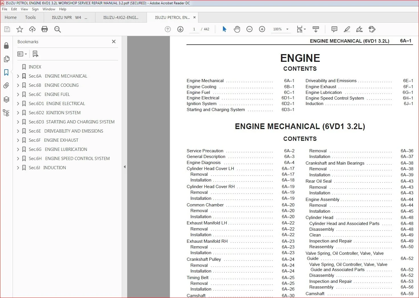
TABLE OF CONTENTS:
ISUZU Petrol Engine 6VD1 3.2L Workshop Service Repair Manual 3.2
INDEX........................................................................................................  0
Sec.6A   ENGINE MECHANICAL...................................................................................  1
	Service Precaution.......................................................................................  2
	General Description......................................................................................  3
	Engine Diagnosis.........................................................................................  4
	Cylinder Head Cover LH................................................................................... 17
		Removal.............................................................................................. 17
		Installation......................................................................................... 18
	Cylinder Head Cover RH................................................................................... 19
		Removal.............................................................................................. 19
		Installation......................................................................................... 19
	Common Chamber........................................................................................... 20
		Removal.............................................................................................. 20
		Installation......................................................................................... 20
	Exhaust Manifold LH...................................................................................... 22
		Removal.............................................................................................. 22
		Installation......................................................................................... 22
	Exhaust Manifold RH...................................................................................... 23
		Removal.............................................................................................. 23
		Installation......................................................................................... 23
	Crankshaft Pulley........................................................................................ 24
		Removal.............................................................................................. 24
		Installation......................................................................................... 24
	Timing Belt.............................................................................................. 25
		Removal.............................................................................................. 25
		Installation......................................................................................... 26
	Camshaft................................................................................................. 30
		Removal.............................................................................................. 30
		Installation......................................................................................... 31
	Cylinder Head............................................................................................ 33
		Removal.............................................................................................. 33
		Installation......................................................................................... 33
	Valve Stem Oil Controller , Valve Spring and Valve Guide................................................. 35
		Removal.............................................................................................. 35
		Installation......................................................................................... 35
	Piston, Piston Ring and Connecting Rod................................................................... 36
		Removal.............................................................................................. 36
		Installation......................................................................................... 37
	Crankshaft and Main Bearings............................................................................. 38
		Removal.............................................................................................. 38
		Installation......................................................................................... 39
	Rear Oil Seal............................................................................................ 43
		Removal.............................................................................................. 43
		Installation......................................................................................... 43
	Engine Assembly.......................................................................................... 44
		Removal.............................................................................................. 44
		Installation......................................................................................... 45
	Cylinder Head............................................................................................ 48
		Cylinder Head and Associated Parts................................................................... 48
		Disassembly.......................................................................................... 48
		Clean................................................................................................ 49
		Inspection and Repair................................................................................ 49
		Reassembly........................................................................................... 50
	Valve Spring, Oil Controller, Valve, Valve Guide......................................................... 52
		Valve Spring, Oil Controller, Valve, Valve Guide and Associated Parts................................ 52
		Disassembly.......................................................................................... 52
		Inspection and Repair................................................................................ 53
		Reassembly........................................................................................... 56
	Camshaft................................................................................................. 59
		Camshaft and Associated Parts........................................................................ 59
		Disassembly.......................................................................................... 59
		Inspection and Repair................................................................................ 60
		Reassembly........................................................................................... 62
	Crankshaft............................................................................................... 65
		Crankshaft and Associated Parts...................................................................... 65
		Disassembly.......................................................................................... 65
		Inspection and Repair................................................................................ 66
		Inspection and Repair................................................................................ 67
		Reassembly........................................................................................... 69
	Piston and Connecting Rod................................................................................ 73
		Piston, Connecting Rod and Associate Parts........................................................... 73
		Disassembly.......................................................................................... 73
		Inspection and Repair................................................................................ 74
		Reassembly........................................................................................... 78
	Cylinder Block........................................................................................... 81
		Cylinder Block and Associated Parts.................................................................. 81
		Disassembly.......................................................................................... 81
		Inspection and Repair................................................................................ 82
		Reassembly........................................................................................... 83
	Main Data and Specification.............................................................................. 86
	Special Tool............................................................................................. 92
Sec.6B   ENGINE COOLING...................................................................................... 94
	Service Precaution....................................................................................... 94
	General Description...................................................................................... 95
	Diagnosis................................................................................................ 97
	Draining and Refilling Cooling System.................................................................... 98
	Water Pump............................................................................................... 99
		Water Pump and Associated Parts...................................................................... 99
		Removal.............................................................................................. 99
		Inspection........................................................................................... 99
		Installation......................................................................................... 99
	Thermostat...............................................................................................100
		Thermostat and Associated Parts......................................................................100
		Removal..............................................................................................100
		Inspection...........................................................................................100
		Installation.........................................................................................100
	Radiator.................................................................................................101
		Radiator and Associated Parts........................................................................101
		Removal..............................................................................................101
		Inspection...........................................................................................102
		Installation.........................................................................................103
	Drive Belt and Cooling Fan...............................................................................105
		Drive Belt and Associated Parts......................................................................105
		Inspection...........................................................................................105
		Installation.........................................................................................105
	Main Data and Specifications.............................................................................106
	Special Tool.............................................................................................107
Sec.6C   ENGINE FUEL.........................................................................................108
	Service Precaution.......................................................................................108
	General Description......................................................................................109
	Fuel Metering............................................................................................110
	Fuel Filter..............................................................................................111
		Removal..............................................................................................111
		Inspection...........................................................................................111
		Installation.........................................................................................111
		Inspection...........................................................................................111
		In‐Tank Fuel Filter..................................................................................111
		Fuel Pump Flow Test..................................................................................111
	Fuel Pump................................................................................................112
		Fuel Pump and Associated Parts.......................................................................112
		Removal..............................................................................................112
		Installation.........................................................................................112
	Fuel Pump Relay..........................................................................................113
		General Description..................................................................................113
	Fuel Tank................................................................................................113
		Fuel Tank and Associated Parts.......................................................................113
		Removal..............................................................................................113
		Installation.........................................................................................114
	Fuel Gauge Unit..........................................................................................114
		Removal and Installation.............................................................................114
	Fuel Filler Cap..........................................................................................114
		General Description..................................................................................114
		Inspection...........................................................................................114
	Main Data and Specifications.............................................................................115
Sec.6D1  ENGINE ELECTRICAL...................................................................................116
	Service Precaution.......................................................................................116
	Battery..................................................................................................117
	General Description......................................................................................117
	Diagnosis................................................................................................117
		Battery Charging.....................................................................................118
		Jump Starting........................................................................................118
		Battery Removal......................................................................................119
		Battery Installation.................................................................................119
		Main Data and Specifications.........................................................................120
Sec.6D2  IGNITION SYSTEM.....................................................................................121
	Service Precaution.......................................................................................121
	General Description......................................................................................122
	Diagnosis................................................................................................122
	Ignition Coil............................................................................................123
		Removal..............................................................................................123
		Inspection and Repair................................................................................123
		Installation.........................................................................................123
	Spark Plug...............................................................................................124
		Removal..............................................................................................124
		Inspection and Repair................................................................................124
		Installation.........................................................................................124
	Crankshaft Angle Sensor..................................................................................125
		Removal..............................................................................................125
		Installation.........................................................................................125
	Main Data and Specifications.............................................................................126
Sec.6D3  STARTING AND CHARGING SYSTEM........................................................................127
	Service Precaution.......................................................................................127
	Starting System..........................................................................................128
	General Description......................................................................................128
	Diagnosis................................................................................................130
	Starter..................................................................................................131
		Removal..............................................................................................131
		Installation.........................................................................................131
		Disassembled View....................................................................................132
		Disassembly..........................................................................................133
		Inspection and Repair................................................................................135
		Reassembly...........................................................................................139
		Main Data and Specifications.........................................................................141
	Charging System..........................................................................................143
	General Description......................................................................................143
	General On‐Vehicle Inspection............................................................................143
	Generator................................................................................................144
		Removal..............................................................................................144
		Inspection...........................................................................................144
		Installation.........................................................................................144
		Disassembled View....................................................................................145
		Disassembly..........................................................................................145
		Inspection and Repair................................................................................148
		Reassembly...........................................................................................150
		Bench Test...........................................................................................150
		Main Data and Specifications.........................................................................151
Sec.6E   DRIVEABILITY AND EMISSIONS..........................................................................152
	Specification............................................................................................155
		Tightening Specifications............................................................................155
	Diagrams and Schematics..................................................................................156
		ECM Wiring Diagram (1 of 6)..........................................................................156
		ECM Wiring Diagram (2 of 6)..........................................................................157
		ECM Wiring Diagram (3 of 6)..........................................................................158
		ECM Wiring Diagram (4 of 6)..........................................................................159
		ECM Wiring Diagram (5 of 6)..........................................................................160
		ECM Wiring Diagram (6 of 6)..........................................................................161
	ECM Pinouts..............................................................................................162
		ECM Pinout Table, 40-Way Connector ‐ “A”.............................................................162
		ECM Pinout Table, 40-Way Connector ‐ “B”.............................................................163
		Component Locators...................................................................................164
		Engine Component Locator Table.......................................................................165
		Undercarriage Component Locator......................................................................166
		Sensors and Miscellaneous Component Locators.........................................................167
	Fuse and Relay Panel (Underhood Electrical Center).......................................................169
	Diagnosis................................................................................................170
		Strategy-Based Diagnostics...........................................................................170
		Strategy-Based Diagnostics...........................................................................170
		DTC Stored...........................................................................................170
		No DTC...............................................................................................170
		No Matching Symptom..................................................................................170
		Intermittents........................................................................................170
		No Trouble Found.....................................................................................170
		Verifying Vehicle Repair.............................................................................170
	General Service Information..............................................................................171
		Maitenance Schedule..................................................................................171
		Visual/Physical Engine Compartment Inspection........................................................171
		Basic Knowledge of Tools Required....................................................................171
	Seral Data Communications................................................................................172
		Class II Serial Data Communications..................................................................172
	On-Board Diagnostic Tests................................................................................172
		On-Board Diagnostic Tests............................................................................172
		Comprehensive Component Monitor Diagnostic Operation.................................................172
		System Status and Drive Cycle for Satisfying Federal Inspection/Maintenance (I/M 240) Regulations....173
		Common OBD Terms.....................................................................................173
		The Diagnostic Executive.............................................................................173
		DTC Types............................................................................................174
		Verifying Vehicle Repair.............................................................................175
		Reading Flash Diagnostic Trouble Codes...............................................................175
		Reading Diagnostic Trouble Codes Using a TECH 2......................................................176
		On-Board Diagnosis (Self-Diagnosis)..................................................................176
		Tech 2 Scan Tool.....................................................................................178
		Getting Started......................................................................................179
		DTC Modes............................................................................................181
		DTC Information Mode.................................................................................181
	Primary System-Based Diagnostics.........................................................................181
		Primary System-Based Diagnostics.....................................................................181
		Fuel Control Heated Oxygen Sensors...................................................................181
		HO2S Heater..........................................................................................181
	Fuel Trim System Monitor Diagnostic Operation............................................................182
	On-Board Diagnostic (OBD) System Check...................................................................183
	A/C Clutch Control Circuit Diagnosis.....................................................................185
	Electronic Ignition System Diagnosis.....................................................................191
	Visual Check of The Evaporative Emission Canister........................................................191
	Fuel Metering System Check...............................................................................191
	Idle Air Control (IAC) Valve.............................................................................191
	Fuel System Pressure Test................................................................................191
	Fuel Injector Coil Test Procedure and Fuel Injector Balance Test Procedure...............................191
	Engine Control Module ECM Diagnosis......................................................................196
	Multiple ECM Information Sensor DTCS Set.................................................................196
	Tech 2 Data Definitions and Ranges.......................................................................199
	Typical Scan Data Values.................................................................................200
	No Malfunction Indicator Lamp (MIL)......................................................................204
	Malfunction Indicator Lamp (MIL) “ON” Steady.............................................................207
	Engine Cranks But Will Not Run...........................................................................210
	Fuel System Electrical Test..............................................................................215
	Fuel System Diagnosis....................................................................................218
	Idle Air Control (IAC) System Check......................................................................223
	Barometric Pressure (BARO) Output Check..................................................................226
	ECM Diagnostic Trouble Codes.............................................................................228
	Diagnostic Trouble Code (DTC) P0101 (Flash DTC=61) MAF System............................................230
	Diagnostic Trouble Code (DTC) P0102 (Flash DTC=61) MAF Sensor Circuit Low Frequency......................233
	Diagnostic Trouble Code (DTC) P0103 (Flash DTC=61) MAF Sensor Circuit High Frequency.....................236
	Diagnostic Trouble Code (DTC) P0107 (Flash DTC=33) BARO Sensor Circuit Low Voltage.......................238
	Diagnostic Trouble Code (DTC) P0108 (Flash DTC=33) BARO Sensor Circuit Hight Voltage.....................241
	Diagnostic Trouble Code (DTC) P0112 (Flash DTC=23) IAT Sensor Circuit Low Voltage........................244
	Diagnostic Trouble Code (DTC) P0113 (Flash DTC=23) IAT Sensor Circuit High Voltage.......................247
	Diagnostic Trouble Code (DTC) P0117 (Flash DTC=14) ECT Sensor Circuit Low Voltage........................250
	Diagnostic Trouble Code (DTC) P0118 (Flash DTC=14) ECT Sensor Circuit High Voltage.......................252
	Diagnostic Trouble Code (DTC) P0121 (Flash DTC=21) TP System Performance.................................255
	Diagnostic Trouble Code (DTC) P0122 (Flash DTC=21) TP Sensor Circuit Low Voltage.........................258
	Diagnostic Trouble Code (DTC) P0123 (Flash DTC=21) TP Sensor Circuit High Voltage........................261
	Diagnostic Trouble Code (DTC) P0131 (Flash DTC=15) HO2S Circuit Low Voltage..............................264
	Diagnostic Trouble Code (DTC) P0132 (Flash DTC) HO2S Circuit High Voltage................................267
	Diagnostic Trouble Code (DTC) P0134 (Flash DTC=15) HO2S Circuit Insufficient Activity....................270
	Diagnostic Trouble Code (DTC) P0171 (Flash DTC=44) Fuel Trim System Too Lean.............................273
	Diagnostic Trouble Code (DTC) P0172 (Flash DTC=45) Fuel Trim System Rich.................................277
	Diagnostic Trouble Code (DTC) P0201 (Flash DTC=31) Injector 1 Control Circuit............................281
	Diagnostic Trouble Code (DTC) P0202 (Flash DTC=31) Injector 2 Control Circuit............................284
	Diagnostic Trouble Code (DTC) P0203 Injector 3 Control Circuit...........................................287
	Diagnostic Trouble Code (DTC) P0204 (Flash DTC=31) Injector 4 Control Circuit............................290
	Diagnostic Trouble Code (DTC) P0205 (Flash DTC=31) Injector 5 Control Circuit............................293
	Diagnostic Trouble Code (DTC) P0206 (Flash DTC=31) Injector 6 Control Circuit............................296
	Diagnostic Trouble Code (DTC) P0336 (Flash DTC=29) CKP Reference Signal Circuit..........................299
	Diagnostic Trouble Code (DTC) P0337 (Flash DTC=29) CKP Sensor Circuit Low Frequency......................301
	Diagnostic Trouble Code (DTC) P0341 (Flash DTC=41) CMP Sensor Circuit Performamce........................303
	Diagnostic Trouble Code (DTC) P0342 (Flash DTC=41) CMP Sensor Circuit Low................................306
	Diagnostic Trouble Code (DTC) P0351 Ignition 1 Control Circuit...........................................310
	Diagnostic Trouble Code (DTC) P0352 (Flash DTC=42) Ignition 2 Control Circuit............................313
	Diagnostic Trouble Code (DTC) P0353 (Flash DTC=42) Ignition 3 Control Circuit............................316
	Diagnostic Trouble Code (DTC) P0354 (Flash DTC=42) Ignition 4 Control Circuit............................319
	Diagnostic Trouble Code (DTC) P0355 (Flash DTC=42) Ignition 5 Control Circuit............................322
	Diagnostic Trouble Code (DTC) P0356 (Flash DTC=42) Ignition 6 Control Circuit............................325
	Diagnostic Trouble Code (DTC) P0502 (Flash DTC=24) VSS No Signal.........................................328
	Diagnostic Trouble Code (DTC) P0562 (Flash DTC=66) System Voltage Low....................................331
	Diagnostic Trouble Code (DTC) P0563 (Flash DTC=66) System Voltage High...................................332
	Diagnostic Trouble Code (DTC) P0601 (Flash DTC=51) ECM Memory............................................333
	Diagnostic Trouble Code (DTC) P1171 (Flash DTC=44) Fuel System Lean Dueing Acceleration..................334
	Diagnostic Trouble Code (DTC) P1508 (Flash DTC=22) IAC System Low RPM....................................337
	Diagnostic Trouble Code (DTC) P1509 (Flash DTC=22) IAC System High RPM...................................340
	Symptom Diagnosis........................................................................................343
	Default Matrix Table.....................................................................................366
	Camshaft Position (CMP) Sensor...........................................................................369
	Crankshaft Position (CKP) Sensor.........................................................................370
	Engine Coolant Temperature (ECT) Sensor..................................................................370
	Heated Oxygen Sensor (HO2S)..............................................................................371
	Intake Air Temperature (IAT) Sensor......................................................................373
	Mass Air Flow (MAF) Sensor...............................................................................373
	Barometric Pressure (BARO) Sensor........................................................................374
	Malfunction Indicator Lamp (MIL).........................................................................374
	Engine Control Module (ECM) .............................................................................374
	EEPROM...................................................................................................375
	Power Steering Pressure (PSP) Switch.....................................................................375
	Throttle Position (TP) Sensor............................................................................376
	Vehicle Speed Sensor (VSS)...............................................................................377
	Air Cleaner/Air Filter...................................................................................378
	Idle Air Control (IAC) Valve.............................................................................379
	Common Chamber...........................................................................................380
	Accelerator Cable Assembly...............................................................................380
	Accelerator Pedal Replacement............................................................................382
	Fuel Fillter Cap.........................................................................................384
	Fuel Filter..............................................................................................384
	Fuel Gauge Unit..........................................................................................386
	Fuel Injectors...........................................................................................386
	Fuel Pressure Regulator..................................................................................387
	Fuel Metering System.....................................................................................389
	Fuel Pump Assembly.......................................................................................389
	Fuel Pump Relay..........................................................................................389
	Fuel Rail Assembly.......................................................................................390
	Fuel Tank................................................................................................391
	Throttle Body (TB).......................................................................................391
	Electronic Ignition System...............................................................................392
	Catalytic Converter......................................................................................393
	Air Conditioning Relay...................................................................................393
	EVAP Canister Hoses......................................................................................393
	EVAP Canister............................................................................................393
	EVAP Canister Purge Solenoid.............................................................................394
	Fuel Tank Vent Valve.....................................................................................395
	Positive Crankcase Ventilation (PCV) Valve...............................................................395
	Wiring and Connectors....................................................................................395
	Wire Harness Repair: Twisted Shielded Cable..............................................................396
	Twisted Leads............................................................................................396
	Weather-Pack Connector...................................................................................398
	Com-Pack III.............................................................................................399
	Metri-Pack...............................................................................................399
	General Description (ECM and Sensors)....................................................................401
	General Description (Air Induction)......................................................................406
	General Description (Fuel Metering)......................................................................406
	General Description (Electronic Ignition System).........................................................409
	A/C Clutch Diagnosis.....................................................................................412
	General Description (Evaporative (EVAP) Emission System).................................................413
	Diagnosis................................................................................................414
	Special Tools............................................................................................416
Sec.6F   ENGINE EXHAUST......................................................................................419
	Service Precaution.......................................................................................419
	General Description......................................................................................420
	Three Way Catalytic Converter and Forked Exhaust Pipe....................................................421
		Three Way Catalytic Converter and Front Exhaust Pipe and Associated Parts............................421
		Removal..............................................................................................421
		Installation.........................................................................................421
	Exhaust Silencer.........................................................................................422
		Exhaust Silencer and Associated Parts................................................................422
		Removal..............................................................................................422
		Installation.........................................................................................422
	Rear Exhaust pipe........................................................................................423
		Rear Exhaust pipe and Associated Parts...............................................................423
		Removal..............................................................................................423
		Installation.........................................................................................423
	Main Data and Specifications.............................................................................424
Sec.6G   ENGINE LUBRICATION..................................................................................425
	Service Precaution.......................................................................................425
	General Description......................................................................................426
	Oil Pump.................................................................................................427
		Oil Pump and Associated Parts........................................................................427
		Disassembly..........................................................................................427
		Inspection and Repair................................................................................428
		Reassembly...........................................................................................429
	Oil Pan and Crankcase....................................................................................431
		Removal..............................................................................................431
		Installation.........................................................................................431
	Oil Pump.................................................................................................434
		Removal..............................................................................................434
		Installation.........................................................................................434
	Oil Pump Oil Seal........................................................................................436
		Removal..............................................................................................436
		Installation.........................................................................................436
	Main Data and Specification..............................................................................437
Sec.6H   ENGINE SPEED CONTROL SYSTEM.........................................................................438
	Service Precaution.......................................................................................438
	Accelerator Pedal Control Cable..........................................................................439
		Removal..............................................................................................439
		Installation.........................................................................................439
		Inspection...........................................................................................439
	Accelerator Pedal........................................................................................440
		Accelerator Pedal and Associated Parts...............................................................440
		Removal..............................................................................................440
		Installation.........................................................................................440
Sec.6J   INDUCTION...........................................................................................441
	Service Precaution.......................................................................................441
	Air Cleaner Element......................................................................................442
		Removal..............................................................................................442
		Inspection...........................................................................................442
		Installation.........................................................................................442
PLEASE NOTE:
- This is the SAME manual used by the dealers to troubleshoot any faults in your vehicle. This can be yours in 2 minutes after the payment is made.
- Contact us at [email protected] should you have any queries before your purchase or that you need any other service / repair / parts operators manual.
Maxwell Caleb –
I had it printed on line. It took quite a while but got it done.