
Iveco Arway Bus Electric & Electronic System Service Manual – Section 14 PDF (603.93.476)
Original price was: $52.95.$34.95Current price is: $34.95.
Complete Iveco Arway electric and electronic system service manual section – 184 pages of wiring rules, ground concepts, control unit pin-outs, CAN network diagrams and the full circuit card set. Instant PDF download.
Description
Iveco Arway Bus Electric & Electronic System Service Manual – Section 14 (603.93.476)
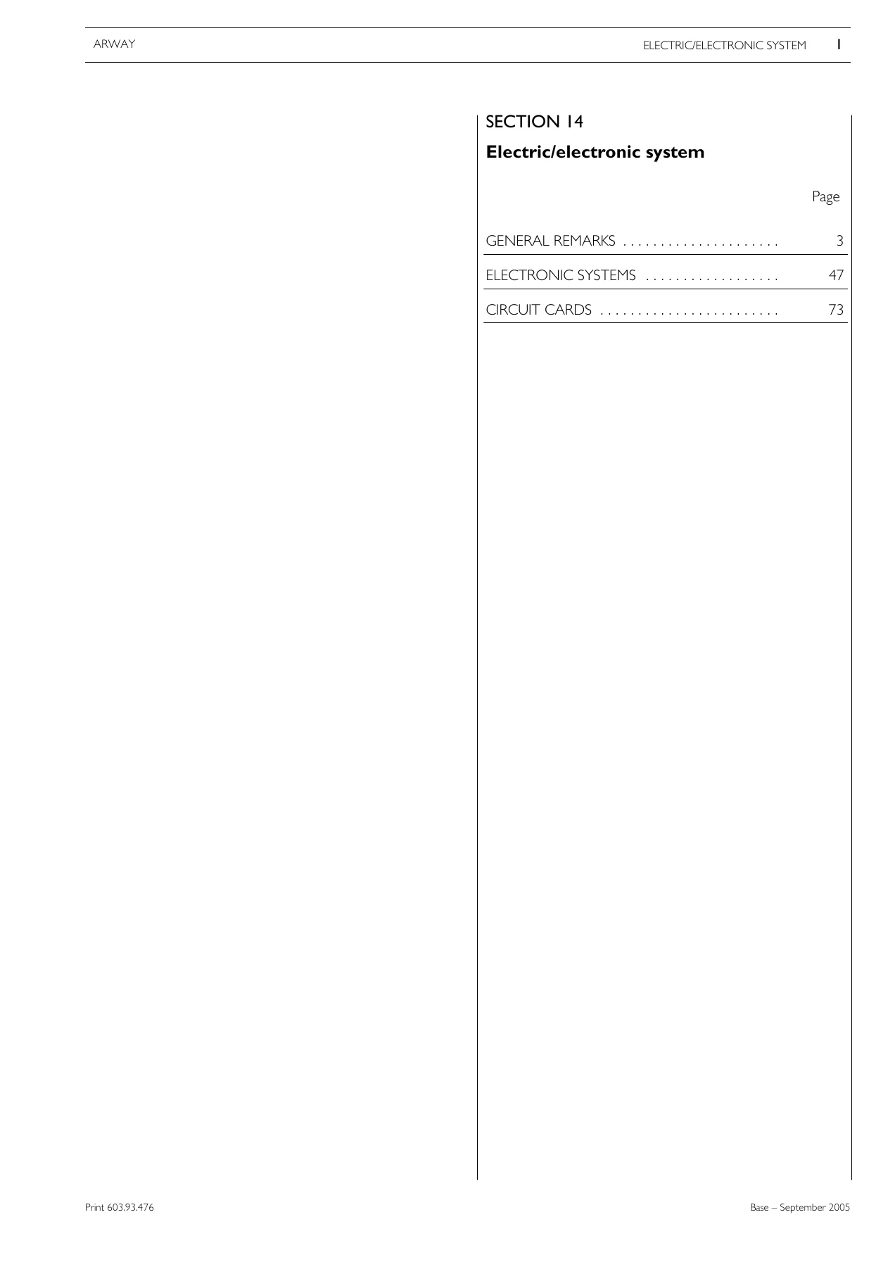
This section of the Iveco Arway service documentation covers the complete electric and electronic system of the Arway bus. Identified by print number 603.93.476 and based on the September 2005 edition, it brings together the general wiring rules, the electronic control architecture, and the full set of circuit cards used on the vehicle. The Arway is a 12 to 12.8 metre bus with two ejecting outswinging service doors, a multiplex electric system running at 24 V, and a centrally mounted IVECO F2B engine.
File Details
- Manual type: Service manual section – electric/electronic system
- Brand: Iveco
- Model: Arway
- Section: 14
- Document number: 603.93.476
- Edition: Base September 2005
- Language: English
- Page count: 184
- File format: PDF
Chapters Covered
- General remarks
- Electronic systems
- Circuit cards
General remarks
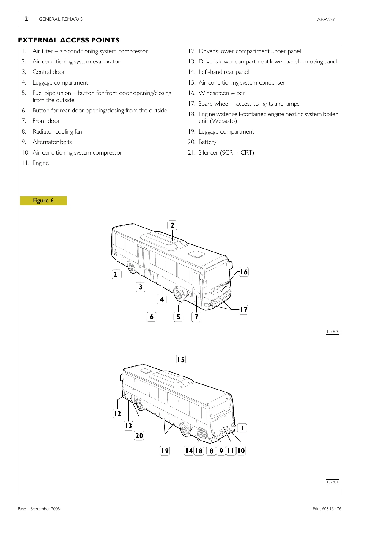
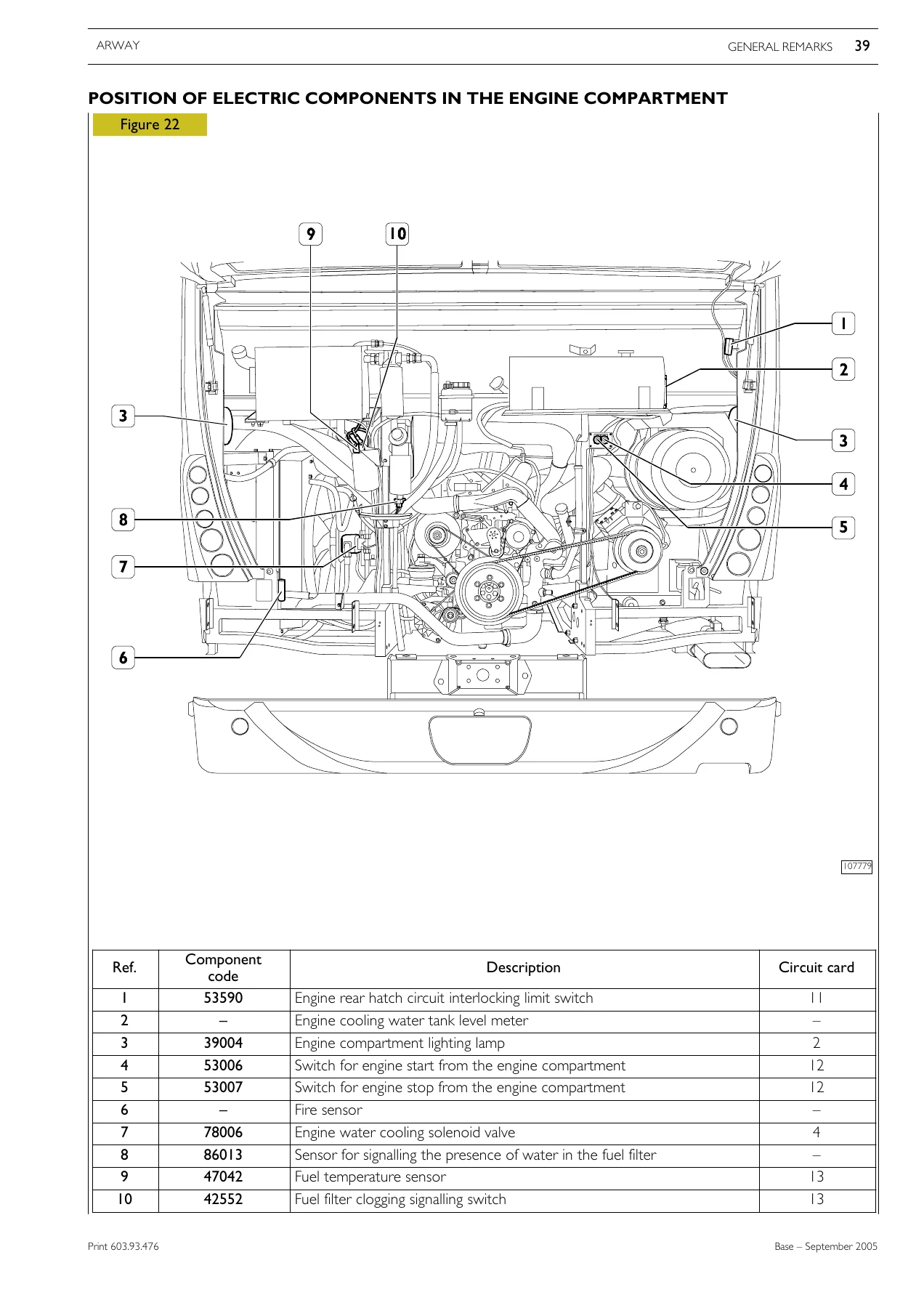
The opening chapter establishes the conditions for working on the wiring diagram and the safety warnings that apply to the whole electric system. It explains electromagnetic compatibility and the ground concept in detail, distinguishing the power supply ground from the analog ground, and shows how negative conductors should be wye connected to the system ground. Ground and screening rules, connector tightening torques and paint restoration at ground points are all described. The chapter then covers installation of electromechanical optional items, external access points, and the main features of the Arway: chassis construction, the IVECO F2B six-cylinder engine, the VOITH Diwa 864.5D automatic transmission, the Meritor U167 rear axle, the RI 75 R independent-wheel front axle and the ZF 8098 steering. Dashboard layouts for the left side and centre, the instrument cluster with all warning lights, the movable panels and rear panel, cable harness initials, and four engine views identify every component. The alternator (MITSUBISHI 28 V 90 A), the starting motor, the pump injector and the BODE outswinging door system with its pneumatic actuator are described with technical views and operating notes.
Electronic systems
This chapter covers the electronic control units and the network that links them. The EDC 7 UC 31 engine control unit is shown with its sensor, injector and chassis connector pin-outs, including the cylinder solenoid assignments and the sensor and actuator functions. The Multibus system is introduced with the CAMU (VBC) central unit and the IOU (Input/Output Unit) peripheral, connected over CAN. A synoptic diagram shows the CAN VDB and CAN EDB lines linking CAMU, IOU, SPRI, tachograph, ABS/ASR, VCM, ECM, DCU, TELMA MCR, SWI and the NOx sensor. Connector pin-outs are given for CAMU CN1 to CN4, IOU CN1 to CN5, the VCM X1 to X3 connectors, and the DCU connector with its AdBlue and urea circuit functions. The digital tachograph (DTCO), the KITAS 2171 sensor and the Knorr ABS/ASR (ABS 6 4S/4M) braking system with its sensors, modulating valves and warning lights are also documented.
Circuit cards
The circuit card chapter contains the full electrical documentation set. Each card shows component codes, cable codes, connector references and switch positions, supported by lists of components and the function of thermal switches with their ratings. Coverage runs from the main power supply, battery and starting circuits, through the alternators, engine management and injector wiring, to the VCM, DCU, TELMA retarder, ABS/ASR, dashboard, external and internal lighting, doors and central locking, heating and ventilation, air conditioning, radio and audio, and the 30-pole diagnosis connector. Fuse and relay positions are listed alongside the cards, so a circuit can be traced from supply to load.
Electronic Control Units & Network
The manual documents the multiplex architecture that replaced conventional wiring on the Arway. The CAMU unit manages the peripheral IOU units over the CAN bus, acquiring inputs, processing the logic functions stored in flash memory and sending outputs back to the peripherals. The IOU units drive motors, lamps and solenoid valves directly and can handle local functions without the CAMU. Because the logic is programmable, the manual notes that the function program can be modified through a diagnosis instrument. Cable colour codes for the CAN H and CAN L lines are given for the MULTIBUS, VDB and EDB networks, which makes it possible to verify continuity and identify the correct pair at any connector.
Alternator, Starting Motor & Pump Injector
Component-level detail is provided for the charging and starting system. The alternator is a MITSUBISHI 28 V 90 A unit with a rated voltage of 28.3 ± 0.5 V, normal operating speed of 5,000 rpm, belt tension of 730 N, clockwise rotation viewed from the pulley, and a terminal B+ tightening torque of 12.5 ± 2 Nm. Its wiring diagram, current delivery curve, technical view and perspective view are included. The starting motor is a 24 V 4.5 kW clockwise unit by DENSO, and its performance curve and terminal layout are shown. The pump injector section explains the plunger, nozzle and solenoid valve construction, notes that the assembly cannot be overhauled or replaced in separate items, and states that a replacement injector must be recognised by the EDC 7 UC 31 control unit.
Doors, Lighting & Body Electrics
The BODE outswinging door system is covered with the electro-pneumatic circuit, the pneumatic actuators, the JOUCOMATIC control blocks above the doors, the solenoid valves for the front and central doors, and the adjustment procedure for the actuator cams and the 30 mm shutter position. External lighting is documented for the front head, rear head and sides, including low and high beam, dimmers, indicators, clearance lights, fog lamps, brake lights, reversing lights, license plate lights and side marker lights. Central locking, the luggage compartment, the driver’s compartment panels and the rear panel are all referenced to their circuit cards.
Why This Manual Matters
Electrical faults on a multiplex bus are rarely solved by swapping parts. They are solved by reading the circuit correctly, checking the right connector pin, and understanding how the control units talk to each other. This section gives the technician the ground rules, the connector pin-outs, the CAN line colour codes, the fuse and relay positions and the full circuit card set needed to trace a fault from the battery to the load. Whether the job is a no-start, a charging fault, a door that will not open, a lighting failure or a dashboard warning, the relevant diagram and pin-out are here. The ground and screening chapter in particular explains why an apparently clean ground point can still cause an intermittent fault, and how to restore a ground connection correctly after repair.
Get the Manual
IMAGES PREVIEW
The Iveco Arway electric and electronic system service manual is delivered as an instant PDF download. There is no shipping and no waiting. Once payment is complete the file is available immediately, and it can be read on a laptop, tablet or phone in the workshop, or printed for the pages you need at the vehicle. Keep it on the shop computer for quick reference, or carry it on a device to the bus. This is the practical reference for anyone maintaining, diagnosing or repairing the electric and electronic system of the Arway.
Reviews
There are no reviews yet.