Iveco N45 & N67 NEF Tier 3 Series Technical & Repair Manual – PDF DOWNLOAD
Original price was: $98.95.$29.95Current price is: $29.95.
Iveco N45 & N67 NEF Tier 3 Series Technical & Repair Manual – PDF DOWNLOAD
NEF TIER 3 SERIES
Industrial application
N45
N45 ENT
N67
N67 ENT
Description
Iveco N45 & N67 NEF Tier 3 Series Technical & Repair Manual – PDF DOWNLOAD
IVECO N45 & N67 NEF TIER 3 SERIES TECHNICAL & REPAIR MANUAL – PDF DOWNLOAD:
IMAGES PREVIEW OF THE MANUAL:
FILE DETAILS:
Iveco N45 & N67 NEF Tier 3 Series Technical & Repair Manual – PDF DOWNLOAD
Format: PDF
Language: English
Brand: Iveco
DESCRIPTION:
Iveco N45 & N67 NEF Tier 3 Series Technical & Repair Manual – PDF DOWNLOAD
NEF TIER 3 SERIES
Industrial application
N45
N45 ENT
N67
N67 ENT
- This publication describes the characteristics, data and correct methods for repair operations on each component of the vehicle. If the instructions provided are followed and the specified equipment is used, correct repair operations in the programmed time will be ensured, safeguarding against possible accidents. Before starting to perform whatever type of repair, ensure that all accident prevention equipment is available and efficient.
- All protections specified by safety regulations, i.e.: goggles, helmet, gloves, boot, etc. must be checked and worn. All machining, lifting and conveying equipment should be inspected before use. The data contained in this publication was correct at the time of going to press but due to possible modifications made by the Manufacturer for reasons of a technical or commercial nature or for adaptation to the legal requirements of the different countries, some changes may have occurred. No part of this publication, including the pictures, may be reproduced in any form or by any means.
GENERAL WARNINGS:
- The manual handling of loads must be assessed in advance because it also depends, besides weight, on its size and on the path.
- Handling by mechanical means must be with hoisters proper as for weight as well as for shape and volume. Hoisters, ropes and hooks used must contain clear indications on maximum carrying capacity acceptable. The use of said means is compulsorily permitted to authorised personnel only.
- Stay duly clear of the load, and, anyhow, never under it.
- In disassembling operations, always observe provided prescriptions; prevent mechanical parts being taken out from accidentally striking workshop personnel.
- Workshop jobs performed in pairs must always be performed in maximum safety; avoid operations which could be dangerous for the co-operator because of lack of visibility or of his/her not correct position.
- Keep personnel not authorised to operations clear of working area.
- You shall get familiar with the operating and safety instructions for the assembly prior to operating on the latter. Strictly follow all the safety indications found on the assembly.
- Do not leave the running assembly unattended when making repairs.
- When carrying out work on the assembly lifted off the ground, verify that the assembly is firmly placed on its supporting stands, and that the manual/automatic safety devices have been actuated in the event that the assembly is to be lifted by means of a hoist.
- When you have to operate on assemblies powered by natural gas, follow the instructions contained in the document, as well as all the specific safety standards provided for.
- Only remove radiator cap when the engine is cold by cautiously unscrewing it in order to let system residual pressure out.
- Inflammable fuel and all inflammable fluids and liquids must be handled with care, according to what contained on harmful materials 12-point cards. Refuelling must be performed outdoors with the engine off, avoiding lit cigarettes, free flames or sparks in order to prevent sudden fires/bursts.
- Adequately store inflammable, corrosive and polluting fluids and liquids according to what provided by regulations in force. Compulsorily avoid to use food containers to store harmful liquids.
- Avoid to drill or bore pressurised containers, and throw cloths impregnated with inflammable substances into suitable containers.
- Worn out, damaged or consumable parts must be replaced by IVECO Motors original spares.
- During workshop activity, always keep the work place clean; timely clear or clean floors from accidental liquid or oil spots.
- Electric sockets and electric equipment necessary to perform repair interventions must meet safety rules.
TABLE OF CONTENTS:
Iveco N45 & N67 NEF Tier 3 Series Technical & Repair Manual – PDF DOWNLOAD
NEF TIER 3 SERIES 1
PRELIMINARY REMARKS 3
SYMBOLS – WARNINGS 3
GENERAL WARNINGS 4
GENERAL WARNINGS ON THE ELECTRIC SYSTEM 6
Bonding and screening 7
OPTIONAL ELECTRICAL AND MECHANICAL PARTS INSTALLATIONS 8
CONVERSIONS BETWEEN THE MAIN UNITS OF MEASUREMENT OF THE INTERNATIONAL SYSTEM AND MOST USED DERIVED QUANTITIES 8
NEF TIER 3 ENGINES 9
Part 1 – F4HE NEF engines 11
SPECIAL REMARKS 13
SYMBOLS – ASSISTANCE OPERATIONS 14
UPDATING 15
SECTION 1 – General specifications 17
CORRESPONDENCE BETWEEN TECHNICAL CODE AND COMMERCIAL CODE 19
LUBRICATION 21
4-cylinder engine version 21
6-cylinder engine version 22
OIL VAPOUR RECYCLING 23
COOLING SYSTEM 24
4-cylinder engine version 24
6-cylinder engine version 25
AIR INDUCTION – BOOST DIAGRAM 26
Description 26
SECTION 2 – Fuel 27
HIGH PRESSURE ELECTRONIC INJECTION SYSTEM (COMMON RAIL) 29
EDC 7 OPERATION 30
WORKING PROCESS 31
FUEL SYSTEM LAYOUT 32
MECHANICAL FEEDING PUMP 33
CP3 HIGH PRESSURE PUMP 34
RAIL 38
BOOST GAUGE VALVE 39
ELECTRO-INJECTOR 40
Electro-injector 41
PRESSURE LIMITER FOR FUEL RETURN 42
SECTION 3 – Duty-industrial application 43
GENERAL SPECIFICATIONS 45
Section pictures of complete engine – common rail version 45
Clearance data – 4 cyl 46
Clearance data – 6 cyl 47
PART ONE – MECHANICAL COMPONENTS 49
ENGINE OVERHAUL 51
Preface 51
Engine setting operations for the assembly on turning stand 51
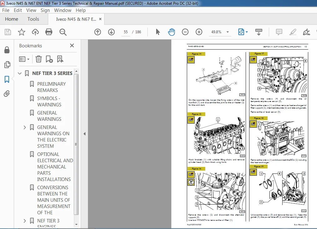
Disassembly of application components 52
Assembly of application components 59
Completion of the engine 71
Checks and inspections 72
PART TWO – ELECTRICAL EQUIPMENT 73
LOCATION OF THE MAIN ELECTRICAL COMPONENTS 75
EDC7 ECU 76
Cable on engine 77
Injectors connector (A) 78
Sensors connector (C) 78
Crankshaft sensor 79
Timing sensor 79
Supercharging air pressure – temperature sensor 80
Engine oil temperature-pressure sensor 80
Fuel temperature and pressure sensor 81
Electro-injectors 82
Pre-post heating resistance and contactor 83
Coolant temperature sensor 84
Fuel temperature sensor 85
High pressure pump – pressure regulator 86
PART THREE – TESTS – TROUBLESHOOTING 87
TESTS 89
CHECKING THE FUEL SYSTEM 89
DESCRIPTION OF TESTS AND CHECKS THAT CAN BE PERFORMED 89
Necessary equipment 89
Low pressure supply test 90
Low-Pressure Pump 91
Test on the pressure relief valve on the rail 92
Test on fuel backflow from the return 93
TROUBLESHOOTING 95
PART FOUR – MAINTENANCE PLANNING 97
MAINTENANCE PLANNING 99
Recovery 99
Regular maintenance and inspection planning 99
Checks not included in maintenance planning-daily checks 100
MAINTENANCE PROCEDURES 100
Checks and inspections 100
Engine oil level check 100
Combustion system inspection 101
Cooling system inspection 101
Lubricating system inspection 101
Inspection of water presence within fuel filter or pre-filter 101
Inspection/replacement of blow-by filter 102
Inspection of drive belt tensioning 102
Inspection and setting of tappet clearance 102
Oil motor and filter replacement 103
Fuel filter replacement 104
Alternator belt replacement 104
SECTION 4 – Overhaul and technical specifications 105
GENERAL SPECIFICATIONS 107
CLEARANCE DATA 108
4 AND 6 ENGINE OVERHAUL 115
ENGINE REMOVAL AT THE BENCH 115
REPAIR OPERATIONS 116
CYLINDER UNIT 116
Checks and measurements 116
Checking head supporting surface on cylinder unit 117
TIMING SYSTEM 118
Camshaft 118
Checking cam lift and pin alignment 119
BUSHES 119
Bush replacement 120
Tappets 120
Fitting tappets — camshaft 121
OUTPUT SHAFT 122
Measuring journals and crankpins 122
Measuring journals and crankpins (6 cyl ) 124
Replacing oil pump control gear 126
Fitting main bearings 126
Finding journal clearance 126
Checking crankshaft shoulder clearance 127
CONNECTING ROD — PISTON ASSEMBLY 127
Pistons 128
Measuring piston diameter 128
Piston pins 129
Conditions for proper pin-piston coupling 129
Connecting rods 130
Bushes 131
Checking connecting rods 132
Checking torsion 132
Checking bending 132
Fitting connecting rod-piston assembly 132
Connecting rod-piston coupling 132
Fitting split rings 133
Fitting connecting rod-piston assembly into cylinder barrels 133
Finding crankpin clearance 134
Checking piston protrusion 135
CYLINDER HEAD 136
Removing the valves 136
Checking cylinder head wet seal 137
Checking cylinder head supporting surface 137
VALVES 138
Removing carbon deposits, checking and grinding valves 138
Checking clearance between valve stem and valve guide and valve centering 138
VALVE GUIDE 139
VALVE SEATS 139
Regrinding — replacing the valve seats 139
CYLINDER HEAD VALVE SEATS (6 CYL ) 140
VALVE SPRINGS 142
FITTING CYLINDER HEAD 142
Refitting the cylinder head 143
TIGHTENING TORQUE 144
SECTION 5 – Tools 147
TOOLS 149
Appendix 157
SAFETY PRESCRIPTIONS 159
Standard safety prescriptions 159
Prevention of injury 159
During maintenance 159
Respect of the Environment 160
Part 2 – G-DRIVE APPLICATION ENGINES 161
SPECIAL REMARKS 163
SYMBOLS – ASSISTANCE OPERATIONS 164
UPDATING 165
SECTION 1 – General specifications 167
CORRESPONDENCE BETWEEN TECHNICAL CODE AND COMMERCIAL CODE 167
COOLING SYSTEM 168
AIR INDUCTION – BOOST DIAGRAM 169
Description 169
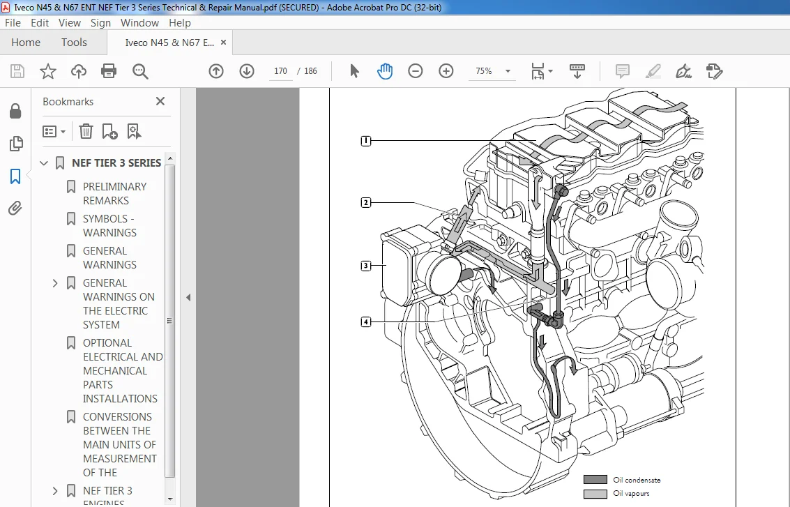
OIL VAPOUR RECYCLING 170
SECTION 2 – G-DRIVE application 171
GENERAL SPECIFICATIONS 171
CLEARANCE DATA 173
REMOVING AND REFITTING ENGINE FROM RADIATOR 179
Removal 179
Refitting 179
TOOLS 180
PLEASE NOTE:
- This is not a physical manual but a digital manual – meaning no physical copy will be couriered to you. The manual can be yours in the next 2 mins as once you make the payment, you will be directed to the download page IMMEDIATELY.
- This is the same manual used by the dealers inorder to diagnose your vehicle of its faults.
- Require some other service manual or have any queries: please WRITE to us at [email protected]


Duncan –
quick and painless
Prince Ernesto –
This experience was good. I am sure I will use heydownloads more in the future.
Dominic Harley –
Always good and I find what I need.