

JCB 540-170 Owners Parts Book 9820/0312D Issue 2 – Loadall Parts Catalog PDF
Original price was: $34.95.$19.95Current price is: $19.95.
Complete JCB 540-170 Owners Parts Book covering serial numbers M2083497 to 3319366. This 1,018-page parts catalog includes exploded views and part numbers for every major assembly including shovels, buckets, hitches, cab, boom, hydraulics, transmission, axles, engine, and more.
Description
JCB 540-170 Owners Parts Book – 9820/0312D Issue 2
This is the complete JCB 540-170 Owners Parts Book, document number 9820/0312D, Issue 2, published August 2023. It covers the JCB 540-170 Loadall telescopic handler for machine serial numbers from M2083497 to 3319366. Written in English, this parts catalog spans 1,018 pages and provides exploded-view illustrations with part numbers for every major assembly on the machine.
Whether you are ordering replacement components, identifying a part number from a diagram, or rebuilding a sub-assembly, this parts book gives you the exact information you need. Every section uses clear exploded illustrations with item-number callouts linked to detailed part number tables showing JCB part numbers, descriptions, and quantities. The level of detail extends from major assemblies right down to individual bolts, washers, seals, and clips.
File Details
- Manual Type: Owners Parts Book / Parts Catalog
- Brand: JCB
- Model: 540-170
- Document Number: 9820/0312D
- Issue: 2
- Publication Date: August 2023
- Language: English
- Page Count: 1,018
- File Format: PDF
- Serial Number Range: M2083497 > 3319366
Chapters Covered
The JCB 540-170 Owners Parts Book is organized into the following major sections, each containing exploded diagrams and corresponding part number tables:
- A01 – Shovels: Shovel installation assemblies, general purpose shovels, bolt-on toe plates, tooth guards, ripper teeth, side marker kits
- A02 – Buckets: Bucket assemblies, man platform installations
- A03 – Hitches: Hitch installation assemblies, loadguard clearview carriage, man platform slew carriage, sideshift carriages, carriage components, hydraulic and manual locking levers, safety guards
- A06 – Agricultural Attachments: Agricultural attachment installations
- A07 – Utility Attachments: Man platforms, utility attachment installations, crane jibs and hooks, fork mounted hooks, extension jibs, hydraulic jibs, roof truss jibs
- B01 – Bodywork/Frame: Pod base, cover assemblies, bodywork installation assemblies, loadall assembly, fenders, engine covers, soundproofing, chassis, fuel tank, hydraulic tank, stabilisers, mounting brackets, bonnet/engine covers/grilles, counterweights, other bodywork items
- B02 – Cab/Canopy: Operator enclosure installation assemblies, cab and canopy builds, roof mouldings, doors, glass/frames, seats, mouldings/trim, other operator enclosure items
- B03 – Boom: Loader installation assemblies, boom lift end, boom common parts, loader arm/boom, boom extension marker, second intermediate boom, loader pivots, boom angle indicator, wear pads, boom retraction sensor, clamps, hose guides
- B05 – Refurbishments: Refurbishment installation assemblies, toolbox, decals, machine identification, warning/information labels, tools, charts, fire extinguisher, lubricants, operator manuals
- C01 – Electrics Main: Electrical installation assemblies for boom, chassis, battery, isolator, lights, alarms, beacons, harnesses, fuses, relays, control units, live link, joystick controls
- C03 – Electrics Cab: Cab electrical installation assemblies, immobiliser, air conditioning, instrument panels, cluster and gauges, switches, heater/air con assembly, radio, fuses and relays
- D01 – Controls: Mechanical control installation assemblies, loader controls, knobs, levers, parking brake, foot pedals, control rods
- D02 – Controls Engine: Throttle control, mounting, vari-inch pedal, electrical throttle, actuator RPM, brackets, cables
- D03 – Controls Steering: Steering installation assemblies, manual/auto steer modes, steering columns, tilt and telescopic, steering wheels, linkages, sensors
- E01 – Hydraulic Circuits: Hydraulic circuit installation assemblies for steering, main circuits, servo controls, loader end, chassis, lift end, boom, high flow, auxiliary, sway, unloader, hose reels
- E02 – Pump & Motors: Pump/motor installation assemblies, 3-stage and 4-stage pumps, emergency pump, gear pumps, fan motors, hydraulic motors
- E03 – Valves: Valve installation assemblies, steer valves, loader valves (2-spool and 5-spool), sway valves, pilot manifolds, proportional valves, counterbalance valves, winch brake valves, dump valves, selector valves
- E04 – Rams: Ram installation assemblies, steer rams, loader crowd/tilt rams, loader lift rams, extension rams, telescopic rams, displacement rams, stabiliser/sway rams, side shift rams, axle lock rams, hydraulic pin lock rams
- E05 – Filter: Filter installation assemblies, kit filter elements, return filter, hydraulic tank filter
- F00 – Transmissions: Transmission installation assemblies, axle pairs, gearboxes, PS750, PS760, 4-speed, 3-speed, 2/4WD, permanent 4WD, various speed ratings (19kph, 29kph, 33kph)
- F01 – Front Axle: Front axle installation assemblies, mountings, sway, pivot mount, trunnion mount, axle arms, hubs, driveheads, differentials, track rods
- F02 – Rear Axle: Rear axle installation assemblies, common parts, remote greasing, trunnion mounting, pivot mounting, pin mounting, hubs, driveheads, differentials, axle lock, track rods
- F03 – Wheels, Tyres & Propshafts: Wheels and tyres, various tyre sizes and brands (Michelin, Goodyear, Firestone, Galaxy, Alliance, Nokian, Mitas, Sitemaster), propshaft installation assemblies, rear propshaft
- F05 – Shuttle Transmission: Shuttle transmission components
- F06 – Powershift: Powershift installation assemblies, bevel gearboxes, speed sensors
- F07 – PTO Gearbox: Bevel/PTO/transfer gearbox installation assemblies, bevel gearboxes, gear and pinion assemblies
- G01 – Brakes: Brake system installation assemblies, servo brakes, master cylinder, brake circuits, front and rear brakes, reservoirs, calipers
- L01 – Engine Assemblies: Engine installation assemblies for all variants, engine assemblies, engine electrics, engine dipstick, fasteners, other engine related parts
- L02 – Exhaust System: Exhaust system installation assemblies, turbocharged exhaust, aftertreatment, DEF systems, AdBlue, silencers, clamps, NOx sensors
- L03 – Induction System: Induction system installation assemblies, air filters, turbocharged, charge air cooling circuits, aspirator circuits
- L04 – Heater: Engine heater installation assemblies, block heaters, grid heaters
- L05 – Oil Sump: Sump drain kits
- L06 – Cooling System: Cooling installation assemblies, header tanks, radiators, expansion tanks, transmission coolers, cooling packs, coolant circuits, hoses and fittings, charge air coolers
- L07 – Fan Installation Assemblies: Fan hydraulics, fan motors, reversing fans, hydraulic fan drives, front end auxiliary drives, idler brackets, air conditioning systems, condensers, receiver driers, compressors
- L08 – Fuel System: Fuel system installation assemblies, fuel coolers, common rail systems, fuel tanks, sedimentors, fuel filters, fuel lubricity filters, fuel hoses and fittings
This JCB 540-170 parts book is a comprehensive resource that covers the complete machine. It is organized so that a technician can work through any system from the exploded diagram to the exact part numbers needed for ordering. Each illustration includes item numbers that correspond to the parts tables, making identification straightforward even for complex assemblies.
Detailed Coverage by Section
Attachments and Hitches
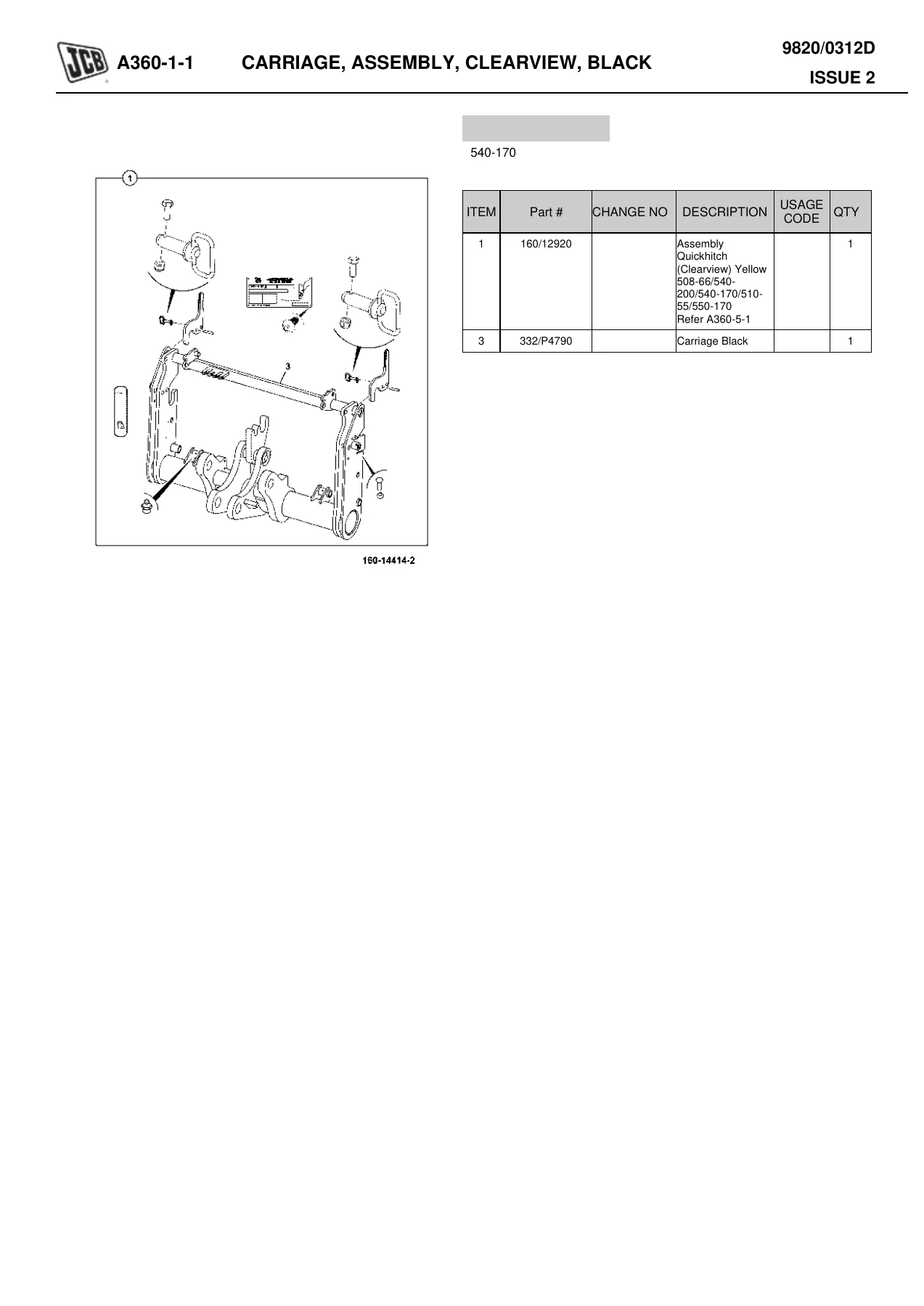
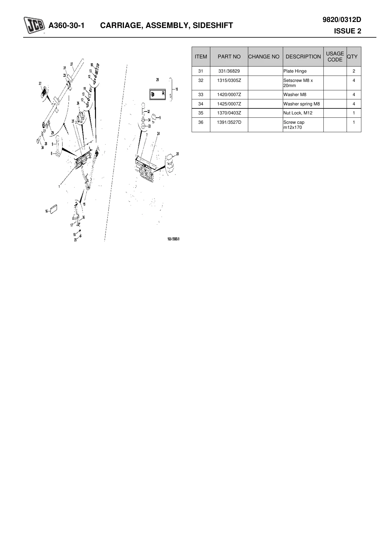
The attachments section covers everything from general purpose shovels and buckets to quickhitch carriages, sideshift carriages, and man platforms. Each attachment is broken down into its component parts with full illustrations, including toe plates, teeth, guards, locking mechanisms, and hydraulic components. The hitch section is particularly detailed, covering clearview carriages, slew carriages, loadguards, and both hydraulic and manual locking systems.
Bodywork and Cab
The bodywork section covers the chassis, pod base, engine covers, fenders, fuel and hydraulic tanks, and stabiliser legs. The cab section includes complete operator enclosure assemblies, doors, glass, seats, trim, and roof mouldings. Both standard and deluxe trim options are documented, along with air conditioning and heating components.
Electrics
Split between main electrics and cab electrics, this section covers the complete electrical system. Harnesses for the boom, chassis, and cab are documented with connectors and routing. Battery installations, isolators, lights, alarms, beacons, fuses, relays, and control units are all covered. Instrument panels, switches, and joystick controls are detailed in the cab electrics section.
Hydraulics
The hydraulic section is extensive, covering every circuit on the machine. From the main hydraulic circuits and steering through to the loader end circuits, servo controls, and high flow systems, every hose, pipe, valve, and ram is documented. The valve section covers steer valves, loader valves in both 2-spool and 5-spool configurations, sway valves, pilot manifolds, proportional valves, counterbalance valves, and more. Ram assemblies are documented for steering, crowd/tilt, lift, extension, telescopic, displacement, stabiliser, sway, side shift, and axle lock applications.
Transmission and Axles
This section covers the complete drivetrain. Transmission installation assemblies are documented for PS750, PS760, and 4-speed gearboxes with various speed ratings and drive configurations. Both front and rear axles are covered with pivot, trunnion, and pin mounting options. Hubs, driveheads, differentials, and track rods are all included. The wheels and tyres section covers a wide range of tyre options from major manufacturers.
Engine and Ancillaries
The engine sections cover everything from the engine assembly itself through to the exhaust, induction, cooling, fuel, and heater systems. Multiple engine variants are documented including Tier 2, Tier 3, Tier 4i, and Tier 4 Final emissions standards. The cooling section covers radiators, charge air coolers, transmission coolers, and complete cooling packs. Fuel system coverage includes common rail systems, sedimentors, fuel coolers, and AdBlue/DEF systems for Tier 4 Final engines.
How to Use This Parts Book
Each section of this JCB 540-170 Owners Parts Book follows a consistent format that makes finding the right part straightforward:
- The exploded illustration shows every component in its correct position and orientation
- Item numbers on the illustration correspond directly to the parts table
- The parts table lists item number, JCB part number, description, and quantity required
- Change numbers are noted where applicable, indicating when a part was updated
- Usage codes help identify which machine variants use specific parts
Why This Parts Book Matters
Having the correct parts book for your JCB 540-170 is essential for efficient maintenance and repair. Without accurate part numbers, ordering replacement components becomes a time-consuming process of trial and error. This book eliminates that problem by providing the exact JCB part number for every component on the machine.
For workshops and service technicians, this parts book is an invaluable reference that saves time on every job. For owner-operators, it means being able to identify and order the correct parts the first time, avoiding costly delays and returns. For parts departments, it provides the complete breakdown needed to support the 540-170 throughout its service life.
The exploded diagrams also serve as assembly guides, showing how components fit together and the correct order of assembly. This is particularly useful when working on complex assemblies like the boom extension, hydraulic valve blocks, or transmission internals.
IMAGES PREVIEW
Instant PDF Delivery
This JCB 540-170 Owners Parts Book is delivered as a PDF file immediately after purchase. There is no shipping, no waiting, and no physical media to lose or damage. The PDF can be viewed on any device — computer, tablet, or smartphone — and can be printed as needed. Whether you need to reference it in the workshop or keep it on file for future use, having the digital version means you always have access to the information you need.
The PDF format allows you to quickly navigate to the section you need, and the detailed illustrations ensure that every component is clearly visible. Whether you are working on a single repair or maintaining a fleet of 540-170 machines, this parts book is a resource you will use again and again.

Reviews
There are no reviews yet.