
JCB 714 & 718 ADT Service Manual – Articulated Dump Truck Workshop Repair Manual PDF
Original price was: $63.95.$39.95Current price is: $39.95.
Complete JCB service manual for the 714 and 718 Articulated Dump Trucks from serial 0830000 and 0832000 onwards. Covers engine, transmission, hydraulics, brakes, steering, electrics, chassis, routine maintenance schedules, torque settings and the 718 hydraulic suspension system in full workshop detail.
Description
JCB 714 & 718 ADT Service Manual – The Complete Workshop Reference
This JCB ADT Service Manual covers the 714 and 718 Articulated Dump Trucks from machine serial number 0830000 onwards (714) and 0832000 onwards (718). Issued as publication 9803/7160, Issue 2, it is the bench reference used for dismantling, overhaul, adjustment, pressure testing and scheduled servicing across every major system on the machine – from the centre pivot and chassis structure through to the hydraulic suspension fitted to the 718. Whether you are chasing an intermittent steering fault, resealing a body lift ram, setting the main relief valve or simply working through the 500 hour service, the procedures and figures are laid out section by section with the illustrations and exploded views to match.
File Details
- Manual type: Service / Workshop Manual
- Brand: JCB
- Models covered: 714 and 718 Articulated Dump Truck (ADT)
- Serial numbers: 0830000 Onwards (714); 0832000 Onwards (718)
- Publication number: 9803/7160
- Edition: Issue 2
- Language: English
- Page count: 383
- File format: PDF
Chapters Covered
- Section 1 – General Information
- Section 2 – Care & Safety
- Section 3 – Routine Maintenance
- Section B – Body and Framework
- Section C – Electrics
- Section E – Hydraulics
- Section F – Transmission
- Section G – Brakes
- Section H – Hydraulic Steering
- Section K – Engine
- Section S – Hydraulic Suspension (ADT 718)
General Information and Safety (Sections 1 and 2)
The opening sections carry the material you reach for before a spanner comes out. The torque setting tables give dry-thread values for UNF Grade ‘S’ bolts, Metric Grade 8.8 bolts and rivet nut bolts and screws, with the note that lubricated threads should be reduced by one third – a detail that catches out plenty of technicians. Vehicle and unit identification is explained, including the layout of the Vehicle Identification Number and where the engine and transmission serial plates are stamped. A numerical service tool list runs through JCB part numbers for ram protection sleeves, hexagon spanners for ram pistons and end caps, the transmission diagnostic kit, the combined comms lead, bearing pullers, pipe swagging tools and glass handling equipment. The sealing and retaining compounds table lists JCB Multi-Gasket, Threadlocker, Retainer, Threadseal, Activator and Anti Seize Paste against their part numbers and intended applications. Care & Safety then sets out the signal-word hierarchy, general safety, operating safety, maintenance safety and the decal system, including the additional suspension warnings that apply specifically to the 718.
Routine Maintenance (Section 3)
The service schedules are broken down by running hours and are one of the most practical parts of this JCB 714 and 718 ADT service manual. Daily 10 hour checks cover engine oil, coolant, hydraulic fluid, display panel operation, leak inspection and windscreen washer level. The 100 hour first service adds air filter hose security, engine drive belt tension, air conditioning compressor belt, engine mount security, wheel nut and axle mount security, transmission security, wiring chafing, battery terminals and charge condition, body down sensor function, seat belt operation and tyre pressures, plus a defined list of lubrication and oil change points. The 500 hour, 1000 hour and 2000 hour intervals follow with their own check, lubricate and change tables. Alongside the schedules there are illustrated greasing procedures covering the tipper body rams and body pivot points, the centre pivot and steering rams, the propshafts and universal joints, the centre bearing carrier and, on the 718, the hydraulic suspension cylinder. Fluids, capacities and lubricants are given separately for the ADT 714 and the ADT 718 with quantities, fluid types and specifications.
Body and Framework (Section B)
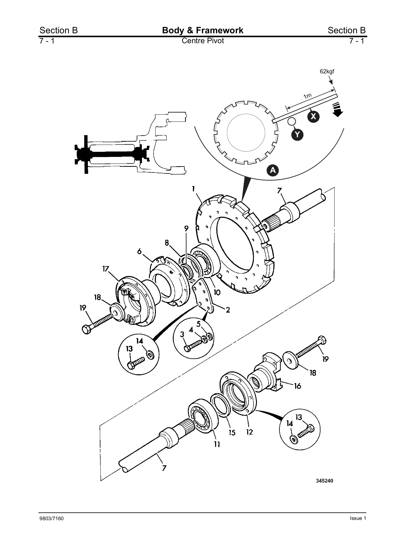
This section deals with the structure rather than the driveline. Direct glazing procedures explain how to remove and refit bonded glass using the correct cut-out tools, braided cutting wire, primers and pre-heated adhesive, with the spacer blocks and glass lifters specified and the difference between laminated front screens and toughened side glass made clear. ROPS/FOPS inspection is covered with the mounting bolt torque of 330 Nm. Separating the front and rear chassis is documented step by step, including loosening the locking ring with a 1 m tommy bar, supporting the modules and re-tightening the locking ring to 1200 Nm. Centre casting removal and replacement follows, with the shim and bearing arrangement for the lower pivot pin, upper pivot and steering ram pins given in full. Rivet nut fitting and the dimensional table for M5 through M10 rivet nuts are included, as is tipper body removal and replacement with its lifting and pin retention requirements.
Electrics (Section C)
Electrical technical data lists the bulb ratings and the complete fuse allocations for both the main ‘CAB REAR’ fuse box and the lighting ‘CAB FRONT’ fuse box, with separate relay maps for the 714 and the 718 – the 718 carries the additional suspension relays. Battery safety, warning symbols, electrolyte first aid, specific gravity testing and load testing with the battery tester are all covered, followed by alternator charging tests and starter motor no-load and locked torque performance figures. The circuit diagrams are reproduced in full with component keys covering fuses, relays, lamps, wiper, washer, beacon, horn, reversing alarm and brake circuits. An air conditioning and heater section explains system operation, thermostat and pressure switch protection, refrigerant type and leak testing, plus component removal for the blower motor, resistor, thermostat switch and pressure switches. Wire and harness number identification explains how each wire number is constructed and what the number ranges mean.
Hydraulics (Section E)
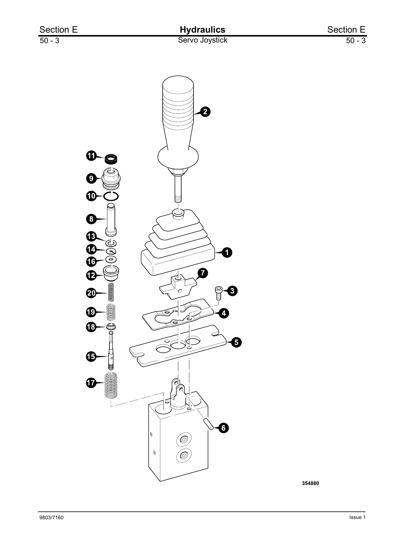
This is a large section and it is where the real diagnostic value of the JCB ADT workshop manual shows. It opens with a full hydraulic schematic symbol reference and then reproduces the machine circuit in component-key form for two build ranges: ADT 714 up to serial 830153 and ADT 718 up to serial 832019, and ADT 714 from serial 830154 and ADT 718 from serial 832020. A dedicated insert shows the 718 hydraulic suspension circuit. Technical data gives primary and secondary pump types and flows, main and auxiliary relief valve pressures, ram bore, rod diameter and stroke, accumulator pre-charge and return line filtration size. Pump removal and replacement is documented, as is the servo joystick fitted to later machines. Control valve operation is explained with flow paths for raise, lower and neutral, and the servo operated variant is covered separately with its own removal and dismantling procedures. Body lift ram removal, dismantling and the JCB ram sealing procedure are set out in detail, including piston head dowel drilling dimensions and end cap seal fitting. Pressure testing procedures cover the main relief valve adjustment, steering stand-by pressure and steer relief valve pressure, each with the test point location and gauge connection.
Transmission (Section F)
Transmission content covers the driveline components and the propshaft removal and replacement procedures referenced from the centre pivot work, including the requirement to mark the flanges at the centre joint before separation so the shafts can be reconnected in the correct orientation.
Brakes (Section G)
The brake section describes the power brake system, tracing fluid from the secondary pump through the charge valve to the brake valve and on to the front and rear brakes, with the accumulators that maintain pressure for a minimum of ten brake applications with the engine stopped. Brake valve removal and replacement is followed by the brake valve setting procedure, which uses the front axle bleed screws and a clear container to set the push rod so that fluid just stops flowing, then shortened a further four flats. Accumulator charge valve removal, dismantling and assembly are covered with the seal kit contents, inspection notes and a torque table for the plugs, relief valve, check valves and cover plate. Service brake pad checking gives the minimum pad thickness of 2 mm, and pad renewal covers both the standard front axle and the twin caliper arrangement on the 718. Bleeding the service brakes is documented for front and rear axles.
Hydraulic Steering (Section H)
Steering technical data and a description of the steering valve follow, explaining the sleeve and spool arrangement, the metering unit with its lobed rotor and stator, and how the load sensing signal is sent to the priority valve. The emergency steering operation is described separately, showing how the emergency steering valve spool moves when pilot pressure is lost and directs emergency pump flow to the steering valve. Hydraulic steering unit removal, dismantling, inspection and assembly are documented in sequence, including the check valve assembly, spool and sleeve timing, spring installation and the final cap screw torque sequence. Emergency steering pump removal, dismantling and assembly are covered with the gear case stud and O-ring arrangement, and steering ram removal and replacement gives the pivot pin, shim and seal details at both rod and eye ends.
Engine (Section K)
Engine service tools are listed, including the de-glazing tool for cylinder bores used when bedding in new piston rings, with a cross reference to the separate engine service manual. Engine related maintenance elsewhere in the manual covers oil level checking and oil and filter changing, cooling system level checking, coolant mixture ratios and draining and refilling, charge air cooler cleaning on Tier 2 engines, drive belt inspection and tension, air conditioning compressor belt adjustment, fuel system specification, sedimenter draining and cleaning, fuel filter changing and fuel system priming.
Hydraulic Suspension – ADT 718 (Section S)
The suspension section applies to the 718 only and covers the self levelling suspension system that supports the front chassis. It explains how to deactivate and reactivate the system safely using the illuminated isolator switch, with the warnings about the front of the machine lowering onto the chassis bump stops when the engine is stopped or the system is deactivated. Hydraulic suspension cylinder removal and replacement is documented, as is dismantling and assembly with the rod seal, groove ring and scraper ring replacement, rod eye torque of 50 Nm and a pressure test at 250 bar. Control arms and the Panhard rod, bump stops and the self levelling sensor switch each have their own removal and replacement procedures. A fault finding table lists error codes S1, S2 and S3 with the detected fault, possible causes and the action required.
What This Manual Lets You Do
With the JCB 714 and 718 ADT service manual on the bench you can carry out the full range of workshop jobs on these machines rather than guessing at them. That means separating the front and rear chassis correctly, removing and resealing body lift rams using the piston head dowel drilling dimensions, adjusting the main relief valve to the specified pressure, setting the brake valve push rod, bleeding front and rear service brakes, timing a steering unit during reassembly, diagnosing an electrical fault from the fuse and relay maps and circuit diagrams, or working through the daily and 500 hour service schedules without missing a lubrication point. The 718 suspension system is covered in its own right, including the safety procedure for deactivating it before any work and the error code table for diagnosing faults.
Correct procedures and the right torque figures matter on articulated dump trucks. A centre pivot locking ring under-torqued, a ram end cap assembled with the wrong seal orientation, a relief valve set by feel rather than by gauge, or a suspension system worked on while still charged all lead to repeat failures, damaged components or worse. The manual removes that guesswork by giving the sequence, the tooling, the seal kit contents and the measured values for each job, with exploded views so the order of components is unambiguous.
Delivery is immediate. This JCB ADT service manual is supplied as a PDF download, so there is no shipping, no waiting and no physical book to keep clean in the workshop. Open it on a laptop, tablet or phone at the machine, print the pages you need for the job in front of you, and keep the rest of the manual intact. Buyers working on both the 714 and the 718 get one document covering both machines and both serial ranges.
IMAGES PREVIEW
Reviews
There are no reviews yet.