

Jcb 8080 Mini Crawler Excavator Parts Catalogue Manual – PDF DOWNLOAD
Original price was: $89.00.$28.95Current price is: $28.95.
LANGUAGE:ENGLISH
PAGES:523
DOWNLOADABLE:YES
FILE TYPE:PDF
Description
📘 DOCUMENT OVERVIEW
This comprehensive digital document serves as a detailed Parts Catalog and Service Manual for JCB 9802/5490 mini crawler excavators. It’s a valuable resource for both professional mechanics and technically inclined DIY enthusiasts looking to maintain and repair their JCB machinery. The manual is meticulously organized, providing clear visual representations alongside detailed part numbers and descriptions. This ensures efficient identification and ordering of replacement parts, streamlining the repair process.
🚜 Equipment Covered: The manual focuses on the JCB 9802/5490 mini crawler excavator, covering a wide range of its attachments and components. Specific models and sub-assemblies are clearly referenced.
🔧 Major Sections and Procedures: The manual is structured into logical sections, each dedicated to a specific area of the machine:
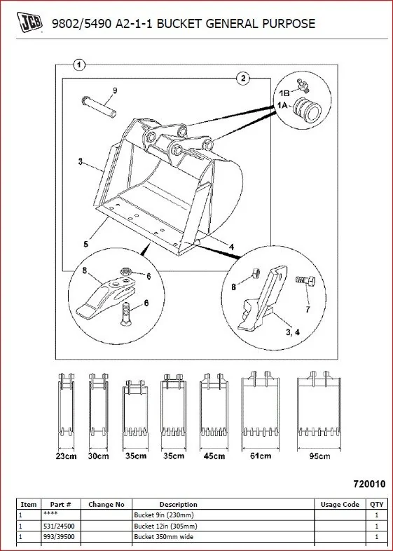
- A02 Buckets: General-purpose buckets of various sizes are detailed with exploded diagrams and parts lists. This section is crucial for identifying and sourcing replacement parts for buckets.
- A2-1-4 Bucket Grading: This section focuses on grading buckets, providing essential technical information for this specific type of bucket.
- A3-1-1 Quick Hitch Mechanical: Detailed diagrams show the parts of the quick hitch system, making troubleshooting and maintenance easier.
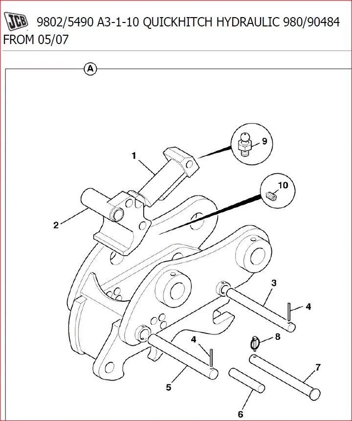
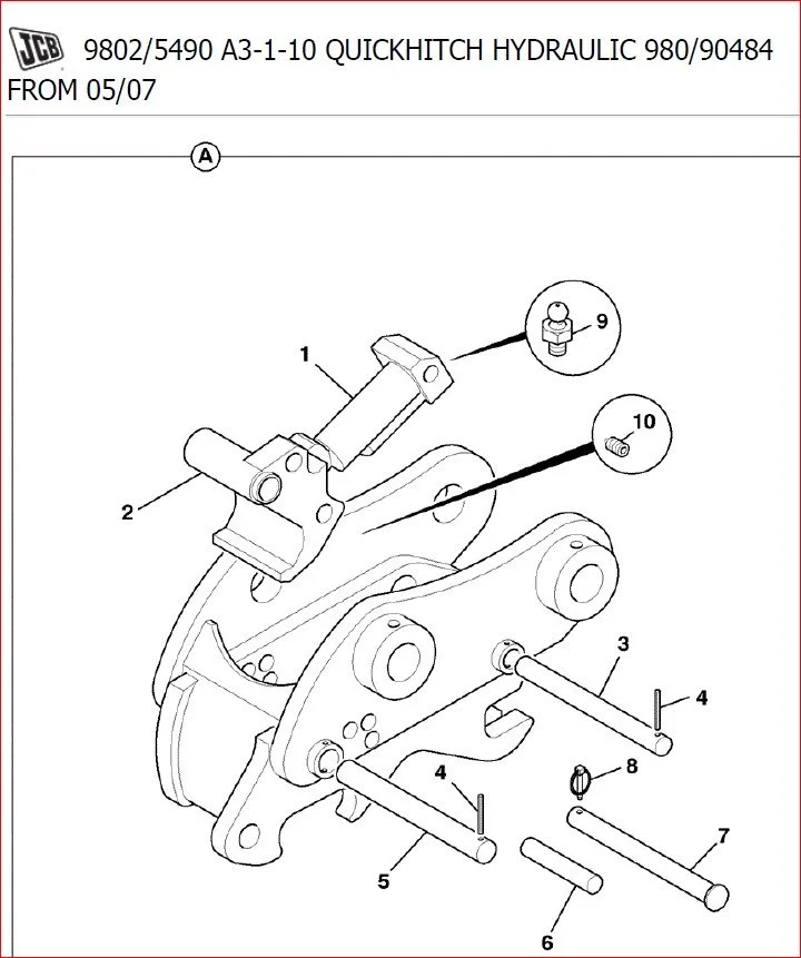
- A3-1-10 Quick Hitch Hydraulic: This section focuses on the hydraulic quick hitch systems and includes parts lists, essential for repair.
- A3-21-1 Kerbgrab Manual 180 KG SWL: The manual provides full documentation on kerbgrab manual attachments.
- A4-1-1 Blade, Dozer: Exploded diagrams and parts lists for various dozer blades allow users to easily find required components.
- B1-1-1 Mainframe & Counterweights: This section is vital for understanding the main structural components of the machine.
- B1-2-1 Tank, Diesel Fuel: Details on the diesel fuel tank and its associated parts are provided.
- B1-3-1 Quick Hitch Hydraulic: This section covers the hydraulic quick hitch system.
- B1-4-1 Floorplates, Mat & Soundproofing: Details on the floorplates and soundproofing materials are provided.
- B1-5-1 Bulkhead & Soundproofing: This section details the bulkhead and its soundproofing components.
- C1-0-0 Cab Harness Locations: The electrical system within the cab is covered comprehensively.
- C1-1-1 Electricals, Main Console Right Hand: Wiring diagrams for the right-hand console help with troubleshooting.
- C1-1-4 Console Left Hand: Similar detailed diagrams for the left-hand console are presented.
- C1-1-6 Fuses and Relays: A clear diagram of fuses and relays in the system.
- C1-3-2 Fuselink Box: Comprehensive details for the fuselink box.
- C2-1-1 Electrical Equipment: Details on major electrical components like the starter motor and alternator.
- C2-2-1 Battery & Leads: Wiring and connection information for the battery system.
- C2-3-2 Starter Motor: A dedicated section for the starter motor with exploded views.
- C2-4-1 Alternator: Detailed diagrams and parts lists for alternators.
- C2-5-1 Alternator Mountings: This section covers mounting components.
- C2-6-1 Engine Auto-Shutdown Optional: Specifics of an optional engine auto-shutdown feature are included.
- C2-7-1 Pump Diesel Refueling: This section shows the components and wiring for the diesel pump.
- C3-2-1 Combined Heater and Air Conditioning Installation: This section explains the installation of a combined heater and air conditioning system.
- C3-2-2 Panel, Control Heater and Aircon: Details on the heating and air conditioning controls panel.
- C3-3-1 Motor, Wiper: Exploded view and parts list for the wiper motor.
- C3-3-2 Screen Washer: This explains the parts and installation of the screen washer system.
- C3-4-1 Light, Working Boom: Comprehensive information on the boom work light and its assembly.
- C3-4-2 Light, Working Cab: This section explains the cab worklight and assembly.
- C3-5-1 Light, Beacon Hazard Warning: This section covers the hazard warning light and its installation.
- C3-6-1 Radio Installation: This section guides on radio installation for the machine.
- C3-8-1 Switch Door Interior Light: Details on the cab door interior light assembly.
- C3-9-1 Heater Unit Installation: Explains the heater unit installation.
- D1-1-1 Controls, Track: Covers the track control system.
- D1-2-1 Controls, Dozer: This section covers the dozer controls assembly.
- D1-4-2 Mounting Servo Controls LH: This covers the left-hand servo control pod.
- D1-4-3 Mounting Servo Controls RH: This covers the right-hand servo control pod.
- D1-5-1 Controls, Swing: This section explains the swing controls assembly.
- D1-10-1 Controls, Low Flow Option: This section covers the low flow option for the machine.
- D1-11-1 Controls, Tab Boom Option: This section deals with the Tab boom option.
- D2-1-1 Control, Throttle: This covers the throttle control assembly.
- D2-1-2 Control, Throttle: Another section of throttle control diagrams.
- E1-2-1 Circuit Servo Hydraulics ISO: This section deals with the servo hydraulic systems using ISO fittings.
- E1-2-2 Circuit Servo Hydraulics SAE: Similar to the previous section but uses SAE fittings.
- E1-3-1 Circuit Slew & Swing Hydraulics: Shows the slew and swing hydraulic systems.
- E1-5-1 Circuit, Excavator Mainframe: The main hydraulic system components of the mainframe are covered in this section.
- E1-7-2 HBCV Pipes and Hoses: This explains the High-Capacity auxiliary system pipes and hoses.
- E1-8-1 Circuit Auxiliary Single Acting: This covers the single-acting auxiliary circuit.
- E1-8-2 Circuit Auxiliary Double Acting: This section focuses on the double-acting auxiliary system.
- E1-8-5 Circuit Auxiliary Low Flow: The low-flow auxiliary hydraulic system is explained in this section.
- E1-15-1 Pump, Main Hydraulic: The main hydraulic pump is covered.
- E1-15-2 Hydraulics Pilot SAE: Covers the SAE pilot hydraulic system.
- E1-15-3 Hydraulics Pilot SAE: This provides additional diagrams of the SAE pilot hydraulic system.
- E1-15-4 Hydraulics Pilot ISO: This section covers the ISO pilot hydraulic system.
- E1-15-5 Hydraulics Pilot ISO: This provides additional diagrams of the ISO pilot hydraulic system.
- E1-20-2 Quick Hitch Installation Kit: This explains the installation kit for the Quickhitch system.
- E3-1-1 Valve,SAE Assembly 10 Spool & Adapters and Low Flow: Covers the valve assemblies and components.
- E3-1-2 Valve, Control Components: This section details the components used in the valve control systems.
- E3-1-10 Valve SAE Assembly 9 Spool & Adapters & ISO/SAE: Details on 9-spool valve assembly.
- E3-1-11 Valve Details 9 Spool: This section provides detailed diagrams of the 9 spool valve.
- E3-1-20 Controller Joystick Right Hand: This focuses on the right-hand joystick controller.
- E3-1-30 Controller Joystick Left Hand: The left-hand joystick controller is explained in this section.
- E3-10-1 Coupling, Rotary: This covers the rotary coupling system.
- E3-11-1 Filter, Hydraulic: This explains the hydraulic filter.
- E3-12-1 Valve Dual Check: This section provides details on the Dual check valve.
- E3-15-1 Accumulator: This section covers the accumulator and its parts.
- E3-16-1 Valve, Track Motor: The track motor valve assembly is covered.
- E3-6-2 Pilot Manifold and Adaptors: Shows the pilot manifold assembly.
- E3-6-3 Load Sensing Block and Adaptors: This covers the load sensing block and its components.
- E3-6-4 Valve Shuttle and Adaptors: This provides the details of the shuttle valve.
- E3-6-5 Valve Sequence and Adaptors: This covers the sequence valve.
- E3-6-6 Valve Auxiliary and Adaptors: Covers the auxiliary valve.
- E3-6-7 Valve Changeover ISO to SAE and Adaptors: This section explains the ISO to SAE changeover valve.
- E4-0-0 Rams Applications: Provides an overview of the different hydraulic ram applications.
- E4-1-1 Ram, Swing: Details of the swing ram are given in this section.
- E4-2-1 Ram, Dozer: This section focuses on the dozer ram.
- E4-2-3 Ram, Dozer HBCV Assembly: Covers the assembly of the dozer ram with HBCV (High-Capacity auxiliary valve) option.
- E4-3-1 Ram, Boom: This section covers the boom ram.
- E4-3-2 Ram, Boom: This provides additional diagrams on the boom ram.
- E4-3-3 Ram, Boom HBCV Assembly: Covers the boom ram assembly with HBCV option.
- E4-3-5 Ram, Boom HBCV Hoses: Covers the hoses for the boom ram with HBCV.
- E4-4-1 Ram, Dipper: This section provides information on the dipper ram.
- E4-4-2 Ram, Dipper HBCV Assembly: Covers the dipper ram assembly with the HBCV option.
- E4-4-3 Tipping Link with 5 Ton Hook: This covers the tipping link with a 5-ton hook.
- E4-4-4 Ram, Dipper HBCV Details: The dipper ram assembly is covered in details.
- E4-6-1 Protection Plates Boom Ram: This explains the boom ram protection plates.
- E4-6-2 Ram Guard Dozer: The dozer ram guard assembly details are available here.
- E4-7-1 Remote Greasing Dipper Ram: This covers the remote greasing system for the dipper ram.
- E4-8-1 Remote Greasing Swing Ram: This explains the remote greasing system for the swing ram.
- E4-9-3 Kerb Grab Ram: This explains the kerbgrab ram.
- E4-11-1 End Cap Assembly: Covers the end cap assembly for the ram.
- F4-1-1 Gearbox, Slew: The slew gearbox is covered in details.
- F4-2-1 Gearbox, Track: Covers the track gearbox.
- F4-2-2 Gearbox Components Track: Provides more detailed information on the track gearbox components.
- J1-1-1 Undercarriage: This section covers the undercarriage system.
- J1-2-1 Idler Wheel & Recoil Unit 450 Wide Rubber Track: Details on idler wheel and recoil unit with rubber tracks.
- J1-2-2 Idler Wheel & Recoil Unit Steel 450 Wide Tracks: This section focuses on steel tracks.
- J1-2-3 Idler Wheel & Recoil Unit Steel 600 Wide Tracks: This section explains the 600-wide steel track idler wheel.
- J1-2-4 Idler Wheel & Recoil Unit Steel 450 Wide Offset: This section covers the offset idler wheel.
- J1-3-1 Roller, Track Top: This covers the top track roller.
- J1-4-1 Roller, Track Bottom: The bottom track roller is explained here.
- J1-5-1 Track Assemblies Rubber 450 Wide: Shows the rubber track assemblies.
- J1-5-2 Track Assemblies Steel 450 Wide: The steel track assemblies (450 wide).
- J1-5-3 Track Assemblies Steel 600 Wide: The steel track assemblies (600 wide).
- J1-5-4 Track Assemblies Steel 450 Wide Offset: This section shows the 450 wide offset steel track assemblies.
- J1-8-1 Chain Guide, Track: The track chain guide is shown here.
- M1-1-1 Engine & Fittings: This provides an overview of the engine and its fittings.
- M1-3-1 Block Assembly: The engine block assembly is discussed here.
- M1-4-1 Crankshaft, Bearings Pistons & Con-Rods: This section explains the crankshaft, bearings, pistons, and connecting rods.
- M1-5-1 Fans, Pulleys & Fan Belt: Details of the engine fan assembly.
- M1-6-1 Timing Case: This section covers the timing case assembly.
- M1-6-2 Camshaft & Gears: Explains the camshaft and its associated gears.
- M1-7-1 Flywheel & Housing: This section shows the flywheel assembly.
- M1-8-1 Engine Mountings: The engine mounting system is described in this section.
- M1-8-2 Engine Mountings Cast/Fabricated: Covers both cast and fabricated engine mountings.
- M1-8-3 Engine Mountings Cast: This section focuses on the cast engine mountings.
- M2-1-1 Cylinder Head: The cylinder head and its components are explained.
- M2-2-1 Rocker Assembly Inlet/Exhaust Valves Push Rods & Tappets: Covers the rocker assembly and its associated parts.
- M2-3-1 Rocker Cover: This section covers the rocker cover.
- M2-4-1 Lifting Plates Engine: This describes the engine lifting plates.
- M3-1-1 Manifold, Induction: Explains the induction manifold.
- M3-2-1 Manifold, Exhaust: The exhaust manifold is detailed.
- M3-3-1 Filter, Air: This section covers the air filter and its components.
- M3-4-1 Exhaust System: Details on the exhaust system are provided.
- M3-4-2 Exhaust System: This section provides additional diagrams for the exhaust system.
- M3-4-3 Exhaust System: This section provides additional diagrams for the exhaust system.
- M4-1-1 Pump, Water: This explains the water pump assembly.
- M4-2-1 Thermostat, Housing Inlet & Outlet: This section shows the thermostat housing.
- M4-3-1 Radiator Fittings & Mountings Cold Climate: This section is specifically for cold climate radiator fittings and mountings.
- M4-3-2 Radiator Fittings & Mountings: This provides details on radiator fittings and mountings.
- M4-4-1 Cooler Assembly Cold Climate: This covers the cooler assembly (cold climate).
- M4-4-2 Cooler Assembly: This covers the cooler assembly.
- M4-5-1 Radiator Hoses & Fittings Cold Climate: This is focused on the cold climate radiator hoses and fittings.
- M4-5-2 Radiator Hoses & Fittings: This covers the radiator hoses and fittings.
- M5-1-1 Sump, Oil & Fittings: This section covers the oil sump and associated parts.
- M5-2-1 Pump, Oil: The oil pump assembly is detailed here.
- M5-4-1 Filter, Oil: This section focuses on the oil filter.
- M5-6-1 Pipes, Oil: This section covers the engine oil pipes.
- M6-1-1 Pump, Fuel Injection Installation: This covers the fuel injection pump.
- M6-1-4 Pump & Governor Fuel Injection Service Parts: This covers the fuel injection service parts.
- M6-2-1 Fuel System: This section shows the fuel system.
- M6-3-2 Injectors Fuel Service Parts: This section focuses on the fuel injectors and their components.
- M6-4-1 Fuel Pipes Fuel Tank to Filter: This explains the fuel pipes from the fuel tank to the filter.
- M6-4-2 Fuel Pipes Fuel Tank to Filter: This explains the fuel pipes from fuel tank to filter.
- M6-4-3 Fuel Pipes Fuel Tank to Filter: This section shows the fuel pipes from fuel tank to filter.
- M6-6-1 Filter Fuel Sedimenter: This covers the fuel sediment filter.
- M6-7-1 Filter Fuel: Details on the fuel filter.
- M6-7-2 Filter Fuel: This explains the fuel filter and assembly.
- M6-7-3 Filter Fuel: This shows the fuel filter.
- M7-3-1 Compressor & Installation Air Conditioning: This section covers the air conditioning compressor and its installation.
- M7-4-1 Compressor Air Conditioning: This covers the air conditioning compressor.
- M8-1-1 Gasket Set, Overhaul: This shows a complete gasket set for engine overhaul.
- M8-2-1 Gasket Set, Overhaul Top: This covers the top gasket set.
- M8-3-1 Kit, Piston & Liner: Covers the piston and liner kit.
- B2-5-1 Seat, Suspension Standard: The manual includes a seat assembly section.
- B2-5-2 Seat, Suspension Standard: This is a second seat assembly section.
- B2-5-3 Seat Belt: This section deals with the seat belt assembly.
- B2-6-1 Seat Base: Details of the seat base are included.
- B2-6-2 Seat, Base: This covers the seat base.
- B2-7-1 Mounting Plate Harness: This provides the mounting plate harness for the cab.
- B2-8-1 Panels Cab: This section deals with the cab panels.
- B2-9-1 Fogs Guard Stage 1: This section explains the fog lights (Stage 1).
- B2-9-2 Fogs Guard Stage 2: This section explains the fog lights (Stage 2).
- B2-10-1 Cab Accessories: This covers accessories for the cab.
- B2-10-11 Mirrors LH & RH: This shows the left and right side mirrors.
- B4-1-1 Kingpost: Details of the kingpost assembly.
- B4-2-1 Boom: This section deals with the boom assembly.
- B4-3-1 Dipper: This section covers the dipper assembly.
- B4-3-2 Dipper, Assembly: This shows the dipper assembly.
- B4-4-1 Bucket Link: The bucket link is covered here.
- B4-4-2 Tipping Link with Lifting Shackle: This section provides details for the tipping link.
- B4-4-3 Tipping Link with 5 Ton Hook: This shows the tipping link with 5-ton hook.
- B4-6-10 Dig End: Covers the dig end assembly.
- B5-2-1 Transfers, Labels & Handbooks: This section covers the decals, transfers, and labels.
- B5-2-2 Labels, Safety & Warning English: This section shows the safety and warning labels in English.
- B5-2-3 Labels, Operation & Control English: Shows operational and control labels.
- B5-2-5 Labels, Safety & Warning German: This section shows safety and warning labels in German.
- B5-2-6 Labels, Operation & Control German: Covers operational and control labels (German).
- B5-2-7 Labels, Operation & Control French: Shows operational and control labels (French).
- B5-2-8 Labels, Safety & Warning Norwegian: Covers safety and warning labels (Norwegian).
- B5-2-9 Labels, Safety & Warning Dutch: Shows safety and warning labels (Dutch).
- B5-2-10 Labels, Safety & Warning Spanish: Shows safety and warning labels (Spanish).
- B5-2-11 Labels, Safety & Warning Italian: Shows safety and warning labels (Italian).
- B5-2-12 Labels, Safety & Warning Danish: Shows safety and warning labels (Danish).
- B5-2-13 Labels, Safety & Warning Portuguese: This shows the safety and warning labels in Portuguese.
- B5-2-14 Labels, Safety & Warning Swedish: This section shows the safety and warning labels (Swedish).
- B5-2-15 Labels, Safety & Warning Belgian: This section shows the safety and warning labels (Belgian).
- B5-2-16 Labels, Safety & Warning Finnish: Covers safety and warning labels (Finnish).
- B5-3-1 Tool Kit: This shows the included tool kit.
- B5-5-1 Oils, Greases & Paint: Lists recommended oils, greases, and paints.
- B1-6-1 Covers, Rear: This covers the rear cab covers.
- B1-6-2 Covers, Side (Engine) Tier 3: This shows the engine side covers.
- B1-6-4 Cover Rear Abi Complete: Shows the complete rear cover assembly.
- B1-6-5 Lock, Assembly: This covers the rear cab lock assembly.
- B1-6-6 Hinge, Assembly: The rear hinge assembly is explained here.
- B1-6-7 Cover, Rear Assembly Yellow: Covers the yellow rear cover.
- B1-6-8 Cover, Rear Assembly Grey: Shows the grey rear cover.
- B1-6-9 Side Hinge Assembly Cast Aluminium: This explains the side hinge assembly (cast aluminium).
- B1-6-10 Rear Hinge Assembly Cast Aluminium: Covers the rear hinge assembly.
- B1-6-11 Panel Rear Mounting: This shows the rear panel mounting assembly.
- B1-6-12 Bonnet Seal Service Kit: The bonnet seal service kit is covered.
- B1-4-1 Floorplates Mat & Soundproofing: This shows floorplates and soundproofing.
- B1-4-2 Floorplates Mat & Soundproofing: This shows floorplates and soundproofing.
- B1-4-3 Seatbase Assembly: This shows the seat base assembly.
- B2-1-1 Kingpost: This is the kingpost section.
- B2-2-1 Cab Mounting: Covers cab mounting.
- B2-2-3 Cab Shell: Shows the cab shell.
- B2-3-1 Cab Door: Details of the cab door are given here.
- B2-4-1 Cab Glazing: This explains the cab glazing.
- B2-4-2 Front Screen Assembly: The front screen assembly.
- B2-4-3 Direct Glazing Replacement Material: This provides material details for direct glazing replacement.
- B2-4-4 Window, Righthand: Covers the right-hand cab window.
- B2-4-5 Window, Lefthand Fixed: Covers the left-hand window.
- B2-4-6 Screen, Roof: The roof screen and assembly.
- B2-4-7 Rear Screen Assembly: This explains the rear screen.
- B2-4-8 Window Door Assembly: This shows the window door.
- Detailed wiring diagrams for all systems.
- Troubleshooting guides for complex issues.
- Overall Quality: High – Comprehensive and well-organized content.
- Content Type: Parts Catalog and Service Manual.
- Language: English.
- Technical Level: Professional/Intermediate.
- Recommended For: Professional mechanics, experienced DIY users, and parts suppliers.
- Page Count: Approximately 160 pages.
- Image Quality: Excellent – Clear and detailed diagrams and illustrations throughout the document.
⚠️ Key Technical Information: The manual is packed with detailed exploded diagrams, parts lists with numbers and descriptions, and technical specifications.
❌ WHAT’S NOT INCLUDED
📊 RECOMMENDATION SUMMARY
| Criteria | Verdict |
|---|---|
| Technical Depth | ⭐⭐⭐⭐☆ |
| Ease of Use | ⭐⭐⭐⭐☆ |
| Model Coverage | ⭐⭐⭐⭐⭐ |
| Value for Technicians | ⭐⭐⭐⭐⭐ |
| Ideal User | Professional mechanics and experienced DIY users |
❓ FREQUENTLY ASKED QUESTIONS
💬 Customer FAQs:
Q: What models does this manual cover?
A: This manual primarily covers the JCB 9802/5490 mini crawler excavator and its various attachments, including different bucket types, quick-hitch systems, and other components. Specific model numbers and sub-assemblies are referenced throughout the document.
Q: What type of procedures are included?
A: The manual provides detailed parts breakdowns, exploded diagrams, and parts lists for various components and sub-assemblies of the JCB 9802/5490. This enables users to readily locate required parts. It covers various systems such as buckets, hydraulics, the engine, cab components, undercarriage, and other crucial elements.
Q: Is this suitable for DIY mechanics?
A: While the manual provides extensive detail, a level of mechanical experience and technical understanding is needed to utilize it effectively. It’s an excellent resource for advanced DIY users but is especially beneficial to professional mechanics.
Q: What format is this manual in?
A: This manual is provided as a digital PDF, accessible immediately after purchase. You can download and view it on various devices, enabling convenient access at any time.
Q: Are there any language requirements?
A: This manual is in English and appears to be intended for a global audience, likely servicing different regions and languages. Although the manual itself is in English, there are multiple language versions of the safety and warning labels found in the document.
Q: What if a part number is incorrect or missing?
A: We strive to ensure accuracy. If you discover an error, please contact us, including the page and part number, to help us improve the content.
Q: Does this include exploded diagrams?
A: Yes, this manual extensively utilizes clear and detailed exploded diagrams to illustrate the location and arrangement of parts for various components and sub-assemblies, facilitating easier identification and maintenance.
📂 PDF SNAPSHOT & USABILITY REPORT
📋 Original Product Description:
Jcb 8080 Mini Crawler Excavator Parts Catalogue Manual Sn 01024000-01025999 01442000-01443999
DESCRIPTION:
JCB 8080 MINI CRAWLER EXCAVATOR maintenance? Are you still worried about JCB 8080 MINI CRAWLER EXCAVATOR failure? If so, I have here a Parts Catalogue manual you must like it, it is a JCB 8080 MINI CRAWLER EXCAVATOR Parts Catalogue manual electronically, its knowledge is rich, is very practical, it is easy to carry, no matter you in site or home, can see anytime and anywhere, it has a comprehensive knowledge of JCB 8080 MINI CRAWLER EXCAVATOR parts, is the best partner of your work. Let me introduce you!
First Professional aspects. This JCB 8080 MINI CRAWLER EXCAVATOR Parts Catalogue manual it learned is rich, which focus on every detail, the purpose of this course is to provide JCB 8080 MINI CRAWLER EXCAVATOR Parts, it is practical, with the method of graphic, better to show you the details of installation and adjustment, it includes many aspects.
Serial Number :
01024000-01025999
01442000-01443999
Parts Catalogue Manual Cover:
ENGINE
BODYWORK
CAB
LOADER
ELECTRICS-MACHINE CAB
CONTROLS-MACHINE ENGINE
HYDRAULICS
AIR
TRACK
SLEW GEARBOX
TRACK
RUNNING GEAR UNDERCARRIAGE


Reviews
There are no reviews yet.