JCB Engines Kohler KDi 1903M & 2504M Workshop Manual – PDF DOWNLOAD
Original price was: $89.00.$28.95Current price is: $28.95.
JCB Engines Kohler KDi 1903M & 2504M Workshop Manual
Description
JCB Engines Kohler KDi 1903M & 2504M Workshop Manual
FILE DETAILS:
JCB Engines Kohler KDi 1903M & 2504M Workshop Manual
Size: 105MB
Fomat: PDF
Language: English
Brand: JCB
Type of machine: Engines Kohler Diesel KDi 1903 TCR- 2504 TCR
Type of document: Workshop Manual
Model: 9806-6850
Page of number: 166
DESCRIPTION:
JCB Engines Kohler KDi 1903M & 2504M Workshop Manual
Useful information:
• This manual contains the instructions needed to carry out proper use and maintenance of the engine, therefore it must always be available, for future reference when required.
• Information, description and pictures in this manual reflect the state of the art at the time of the marketing of engine.
• However, the development of engines is continuous. Therefore, the information in this manual is subject to change without notice.
• KOHLER reserves the right to make, at any time, changes on the engines for technical or commercial reasons.
• These changes do not require KOHLER to intervene on the production marketed up to that time and nor to consider this manual as inappropriate.
• The paragraphs, tables and figures are numbered by chapter and followed by the progressive paragraph, table and/or figure number.
E.g.: Par. 1.3 – chapter 1 paragraph 3.
Tab. 2.4 – chapter 2 table 4.
Fig. 4.5 – chapter 4 figure 5.
• The references of the objects described in the text and in the figure are indicated by letters and numbers, which are always and only related to the paragraph you are reading unless there are specific references to other figures or paragraphs.
• Reference to values are indicated by letters or numbers (in red and underlined).
• Other important references are highlighted in red.
• The pictures are based on model KDI 2504 M, where necessary KDI 1903 M model is illustrated.
• All technical terms, specific components and symbols (Tab. 15.1) that are in the manual are listed and described inside the glossary, which can be consulted in (Chap. 15).
• Any additional section that KOHLER will deem necessary to supply at a later stage must be kept with the manual and considered as an integral part of it.
• The information contained in this manual is the sole property of KOHLER, therefore no partial or total reproduction or replication is allowed without the express permission of KOHLER.
TABLE OF CONTENTS:
JCB Engines Kohler KDi 1903M & 2504M Workshop Manual
1 GENERAL INFORMATION 12
1.1 Useful information 12
1.1.1 Useful Information -accident prevention – environmental impact 12
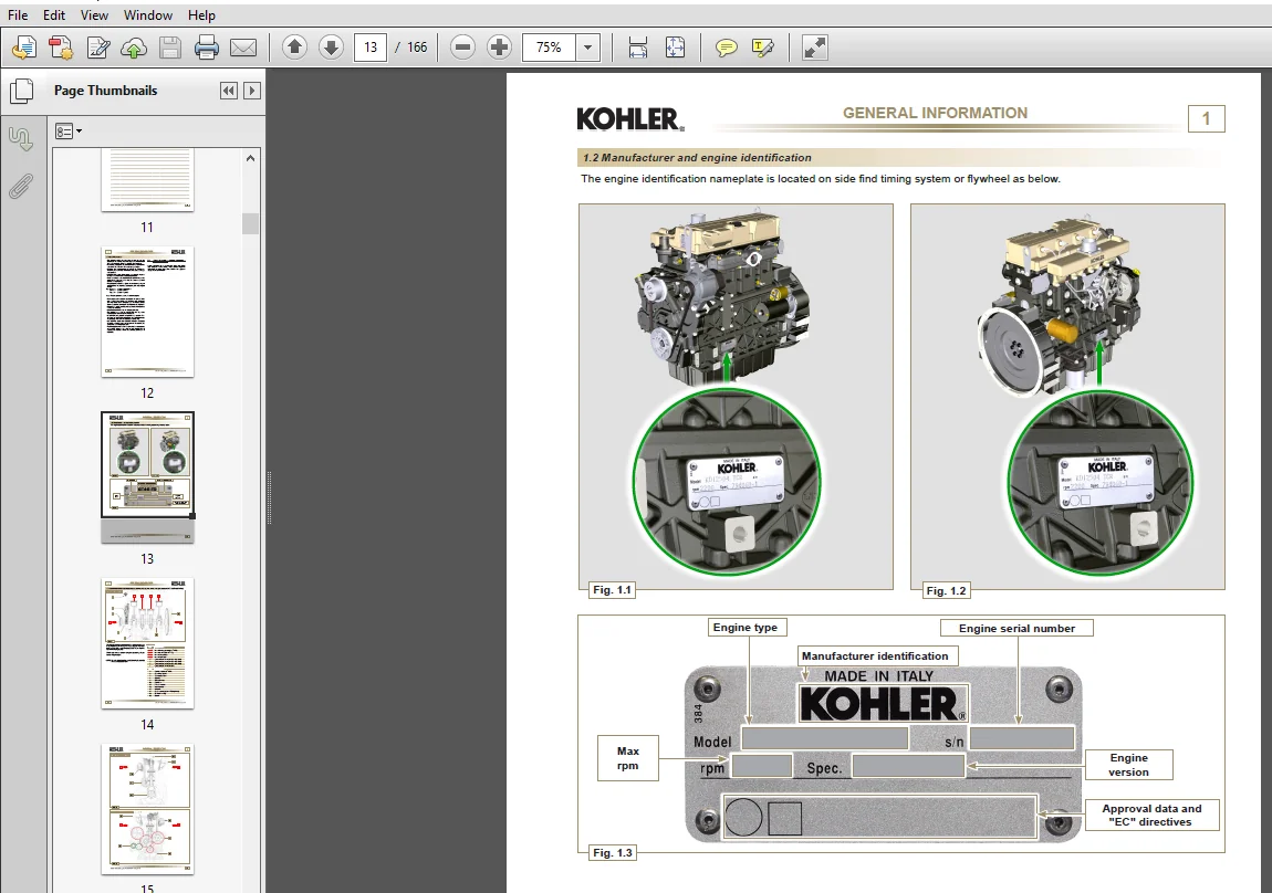
1.2 Manufacturer and engine identification 13
1.3 Identification of the main internal components of the engine and operating reference (BASE CONFIGURATION) 14
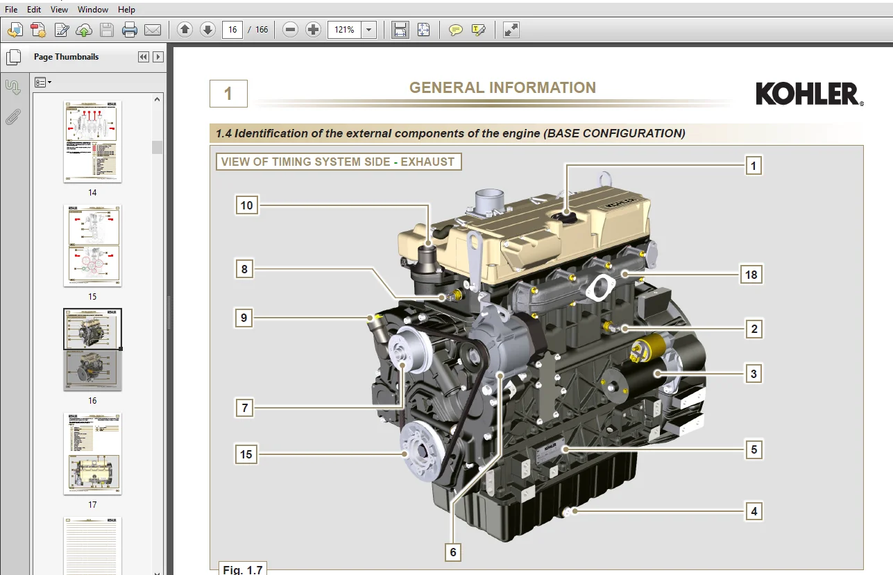
1.4 Identification of the external components of the engine (BASE CONFIGURATION) 16
2 TECHNICAL INFORMATION 19
2.1 Engine specifications 19
2.2 Engine dimensions (mm) 21
2.3 Performance diagrams 22
2.4 Oil 23
2.4.1 SAE oil classification 23
2.4.2 International lubricant specifications 23
2.5 Fuel 24
2.5.1 Fuel for low temperatures 24
2.5.2 Biodiesel fuel 24
2.5.3 Emission-Related Installation Instructions 25
2.6 Coolant 25
2.7 Battery features 25
2.8 Periodic maintenance 26
2.9 Fuel system 27
2.9.1 Supply system 27
2.9.2 Fuel return circuit 28
2.9.3 Injection pump 28
2.9.4 Injector 29
2.9.5 Fuel filter 29
2.9.6 Electric fuel pump (optional) 30
2.9.7 Guards for fuel injection circuit components 30
2.10 Lubrication circuit 31
2.10.1 Lubrication circuit diagram 31
2.10.2 Oil pump 32
2.10.3 Oil filter 33
2.11 Coolant circuit 34
2.11.1 Coolant circuit diagram 34
2.11.2 Coolant pump 34
2.11.3 Thermostatic valve 34
2.11.4 Radiator (optional) 35
2.12 Intake and exhaust circuit 36
2.12.1 Air filter (optional) 37
2.13 Electric system 38
2.13.1 Engine electrical wiring (opzional) 38
2.13.1.1 Connector panel on the engine/machine 39
2.13.1.2 Accessories panel connector 39
2.13.1.3 Wiring disconnection 40
2.14 Sensors and switches 41
2.14.1 Fuel filter water detection sensor 41
2.14.2 Oil pressure switch 41
2.14.3 Coolant temperature sensor 41
2.14.4 Air cleaner clogging switch 42
2.15 Electrical components 42
2.15.1 Alternator 42
2.15.2 Starter motor 42
2.15.3 Cold starting device (Heater) 42
2.15.4 Electric fuel pump (optional) 43
2.15.5 Cold Start Advance 44
2.15.6 Electro-Stop 44
2.15.7 Fuse 44
2.15.8 Control panel (optional) 44
2.16 Timing system and tappets 45
2.16.1 Components identification 45
2.16.2 Timing system phasing angles 46
5
MO KDI 1903M_2504M_code ED0053029610 – 4th ed_rev. 03
INDEX
2.16.3 Rocker arm pin 46
2.16.4 Rocker arms 46
2.16.5 Hydraulic tappets 47
2.16.5.1 Hydraulic tappet operation 47
2.16.5.2 Difficult operating conditions 47
2.17 Balancer device (optional – only KDI 2504) 48
2.18 Components handling 49
2.18.1 Injection pump 49
2.18.2 Injector 49
3 SAFETY INFORMATION 50
3.1 Before start-up 50
3.2 Safety precautions 50
3.3 General remarks 50
3.3.1 Note for OEM 50
3.3.2 Note for end user 50
3.4 Safety signal description 52
3.4.1 Adhesive safety plates 52
3.4.2 Warnings 52
3.4.3 Safety guards 52
3.5 Information and safety signals 53
3.6 Safety and environmental impact 53
3.7 Location of safety signals on engine 54
4 STORAGE INFORMATION 55
4.1 Product preservation 55
4.2 Engine storage (up to 6 months) 55
4.3 Engine storage (over 6 months) 55
4.4 Engine starting after storage 55
5 INFORMATION REGARDING DISCHARGE OF LIQUIDS 56
5.1 Coolant 56
5.2 Engine oil 57
6 INFORMATION FOR REPLACING THE FUNCTIONAL UNITS 58
6.1 Injector and injection pump replacement 58
6.1.1 Injection fuel pipes disassembly(injection pump/injectors) 58
6.1.2 Rocker arms cover disassembly 58
6.1.3 Fuel return pipes disassembly 59
6.1.4 Injectors disassembly 59
6.1.5 Injection pump disassembly 59
6.1.6 Injection pump assembly 62
6.1.7 Injector assembly 63
6.1.8 Assembly of the injector return pipes 64
6.1.9 Assembly Rocker arm cover 64
6.1.10 Installation of the fuel injector pipes (pump injector/injectors) 65
6.2 Coolant pump replacement 66
6.2.1 Disassembly 66
6.2.2 Assembly 66
6.3 Replace the crankshaft pulley 67
6.3.1 Disassembly 67
6.3.2 Assembly 67
6.4 Oil pump replacement 68
6.4.1 Coolant pump disassembly 68
6.4.2 Engine pulley disassembly 68
6.4.3 Timing system crankcase disassembly 68
6.4.4 Oil pump disassembly 68
6.4.5 Oil pump assembly 69
6.4.6 Timing system crankcase assembly 69
6.4.7 Crankshaft pulley assembly 70
6.4.8 Coolant pump assembly 70
6.5 Oil pressure valve replacement 70
6.5.1 Disassembly 70
6.5.2 Assembly 70
6
MO KDI 1903M_2504M_code ED0053029610 – 4th ed_rev. 03
INDEX
6.6 Oil filter replacement 71
6.6.1 Disassembly 71
6.6.2 Assembly 71
6.7 Fuel filter replacement 71
6.7.1 Disassembly 71
6.7.2 Assembly 71
7 DISASSEMBLY INFORMATION 72
7.1 Recommendations for disassembly 72
7.2 Electric components disassembly 72
7.2.1 Electric wiring 72
7.2.2 Starter motor 72
7.2.3 Belt and alternator 72
7.2.4 Sensors and switches 72
7.2.4.1 Oil pressure switch disassembly 72
7.2.4.2 Coolant temperature sensor 73
7.2.4.3 Fuel filter water detection sensor 73
7.3 Exhaust manifold disassembly 73
7.4 Coolant recirculation components disassembly 73
7.4.1 Coolant pump 73
7.4.2 Thermostatic valve 74
7.5 Crankshaft pulley disassembly 74
7.6 Lubrication circuit disassembly 74
7.6.1 Oil pressure valve 74
7.6.2 Timing system carter oil filling flange 74
7.6.3 Timing system 75
7.6.4 Oil pump 75
7.6.5 Oil cooler unit 75
7.7 Intake manifold disassembly 76
7.8 Fuel system disassembly 76
7.8.1 Fuel injection pipes 76
7.8.2 Rocker arm cover 76
7.8.3 Fuel return pipes 77
7.8.4 Injector 77
7.8.5 Injection pump 77
7.8.6 Fuel filter 78
7.9 Timing system gear disassembly 78
7.10 Flange unit disassembly 79
7.10.1 Flywheel 79
7.10.2 Flange housing 79
7.11 Cylinder head unit disassembly 80
7.11.1 Rocker arm pin 80
7.11.1.1 Rocker arm 80
7.11.2 Valve rods and bridges 80
7.11.3 Cylinder head 81
7.11.3.1 Valves 81
7.11.3.2 Injector sleeve 82
7.11.3.3 Valve stem gasket 82
7.11.3.4 Lifting eyebolts 82
7.12 Oil sump unit disassembly 83
7.12.1 Oil sump 83
7.12.2 Oil intake pipe 83
7.12.3 Oil vapour pipe 83
7.13 Engine block disassembly 84
7.13.1 Crankshaft gasket flange 84
7.13.2 Piston unit / connecting rod 84
7.13.3 Lower semi-crankcase 85
7.13.4 Crankshaft 86
7.13.5 Piston 86
7.13.5.1 Rings 87
7.13.6 Breather room closing cover 87
7.13.7 Camshaft 87
7.13.8 Camshaft tappets 87
7.13.9 Crankshaft bushings 88
7.13.10 Cover 3at PTO 88
7
MO KDI 1903M_2504M_code ED0053029610 – 4th ed_rev. 03
INDEX 8 INFORMATION ABOUT OVERHAULING 90
8.1 Recommendations for overhauls and tuning 90
8.2 Crankcase 91
8.2.1 Oil line check 91
8.2.2 Cylinder check 92
8.2.3 4-cylinder camshaft housing check 93
8.2.4 Camshaft control for 4 cylinder engine 93
8.2.5 Camshaft housing check for 3 cylinder engine 94
8.2.6 Camshaft control for 3 cylinder engine 94
8.3 Tappets and tappet housings 95
8.3.1 Tappets check 95
8.3.2 Tappet housing check 95
8.4 Crankshaft 96
8.4.1 Dimensional check and overhauling 96
8.4.2 Checking the axial clearance of the crankshaft 97
8.5 Connecting rod – piston assembly 97
8.5.1 Connecting rod dimensions check 97
8.5.2 Checking the gudgeon pin-pin axes are parallel 98
8.5.3 Piston rings check 98
8.5.4 Piston dimension check 98
8.6 Cylinder head 99
8.6.1 Flatness check 99
8.6.2 Valve seats check 100
8.6.3 Valve springs 100
8.6.4 Valve guides check 100
8.6.5 Valve guides replacement 101
8.6.6 Valve guides replacement 101
8.7 Oil pump check 102
8.7.1 Dimensional and visual check 102
8.7.2 Rotors clearance check 102
8.7.3 Oil pressure valve check 103
9 ASSEMBLY INFORMATION 104
9.1 Information on engine configuration 104
9.2 Assembly recommendations 104
9.3 Engine block assembly 105
9.3.1 Semi main bearings 105
9.3.2 Tappets 105
9.3.3 Camshaft 105
9.3.4 Breather room closing cover 106
9.3.5 Crankshaft 106
9.3.6 Lower crankcase 106
9.3.7 Piston rings 108
9.3.8 Piston 108
9.3.9 Piston and connecting rod assembly 109
9.3.10 Crankshaft gasket flange 110
9.3.11 Cover 3rd PTO 110
9.4 Oil sump unit assembly 111
9.4.1 Oil vapour pipe 111
9.4.2 Oil suction pipe 111
9.4.3 Oil Sump 111
9.5 Flange unit assembly 112
9.5.1 Bell housing 112
9.5.2 Flywheel 112
9.6 Timing system gear assembly and injection pump 113
9.6.1 Timing system gear assembly 113
9.6.2 Injection pump 114
9.7 Cylinder head unit assembly 115
9.7.1 Valve stem gasket 115
9.7.2 Injector sleeves 115
9.7.3 Injectors projection 115
9.7.4 Valves 116
9.7.5 Cylinder head 116
9.7.6 Rods and valve bridges 118
8
MO KDI 1903M_2504M_code ED0053029610 – 4th ed_rev. 03
INDEX
9.7.7 Rocker arms 119
9.7.8 Rocker arm pin assembly 119
9.8 Fuel system assembly 120
9.8.1 Injector 120
9.8.2 Fuel injector ricicle pipe 121
9.8.3 Rocker arm cover 121
9.8.4 Installation of the fuel injector pipes (injection pump/injectors) 122
9.8.5 Fuel filter 122
9.9 Intake manifold assembly 123
9.10 Exhaust manifold assembly 123
9.11 Lubrication circuit 123
9.11.1 Oil filter 123
9.11.2 Oil pump 123
9.11.3 Timing system crankcase 124
9.11.4 Crankcase oil filler flange Timing System 125
9.11.5 Oil pressure relief valve 125
9.12 Crankshaft pulley assembly 125
9.13 Coolant circuit assembly 125
9.13.1 Thermostatic valve 125
9.13.2 Coolant pump 126
9.14 Electric component assembly 126
9.14.1 Sensors and switches 126
9.14.1.1 Water temperature sensor 126
9.14.1.2 Oil Pressure Switch 126
9.14.1.3 Fuel filter water detection sensor 126
9.14.2 Alternator 127
9.14.3 Starter Motor 127
9.15 Summary table of tightening torques and the use of sealants 128
10 FLUIDS SUPPLY INFORMATION 132
10.1 Engine oil 132
10.2 Coolant 132
11 INFORMATION ABOUT OPTIONAL COMPONENTS 134
11.1 Oil dipstick in cylinder head 134
11.1.1 Check 134
11.1.2 Replacement 134
11.1.2.1 Disassembly 134
11.1.2.2 Assembly 134
11.2 Heater (replacement) 135
11.2.1 Disassembly 135
11.2.2 Assembly 135
11.3 Idler gear (for 3rd / 4th PTO) 136
11.3.1 Disassembly 136
11.3.2 Assembly 136
11.4 3rd PTO (replacement) 137
11.4.1 Disassembly 137
11.4.2 Assembly 138
11.5 4th PTO (replacement) 139
11.5.1 Disassembly 140
11.5.2 Assembly 141
11.6 3rd + 4th PTO (configurations) 143
11.6.1 Information 143
11.7 Balancer device (replacement) 144
11.7.1 Disassembly 144
11.7.2 Assembly 145
11.8 Air filter (cartridge replacement) 147
11.9 Remote oil filter (disassembly and assembly) 147
11.9.1 Disassembly 147
11.9.2 Assembly 148
11.10 Intake circuit (replacement) 149
11.10.1 Air filter disassembly 149
11.10.2 Manifold air filter disassembly 149
11.10.3 Air filter manifold assembly 149
11.10.4 Air filter assembly 149
9
MO KDI 1903M_2504M_code ED0053029610 – 4th ed_rev. 03
INDEX
11.11 Muffler (replacement) 150
11.11.1 Disassembly 150
11.11.2 Assembly 150
11.12 Cooling circuit (replacement) 150
11.12.1 Radiator disassembly 150
11.12.2 Fan disassembly 151
11.12.3 Fan assembly 152
11.12.4 Radiator assembly 152
11.13 Engine feet (information) 153
12 INFORMATION ON ADJUSTMENTS and checks 154
12.1 Air filter check 154
12.2 Rubber hose and manifold control 154
12.3 Oil leak check 155
12.4 Oil pressure check 155
13 tools information 156
13.1 Information regarding specific tools 165
14 INFORMATION about failures 160
14.1 Possible causes and trouble shooting 160
15 GLOSSARY 162
Questions? Email us: [email protected]
IMAGES PREVIEW OF THE MANUAL:
PLEASE NOTE:
- This is the same manual used by the dealers to diagnose and troubleshoot your vehicle
- You will be directed to the download page as soon as the purchase is completed. The whole payment and downloading process will take anywhere between 2-5 minutes
- Need any other service / repair / parts manual, please feel free to contact [email protected] . We still have 50,000 manuals unlisted