JLG 1500SJ Service & Maintenance Manual 3121262 – PDF DOWNLOAD
$26.95
JLG 1500SJ Service & Maintenance Manual 3121262 – PDF DOWNLOAD
Description
JLG 1500SJ Service & Maintenance Manual 3121262 – PDF DOWNLOAD
FILE DETAILS:
JLG 1500SJ Service & Maintenance Manual 3121262 – PDF DOWNLOAD
Language : English
Pages : 628
Downloadable : Yes
File Type : PDF
DESCRIPTION:
JLG 1500SJ Service & Maintenance Manual 3121262 – PDF DOWNLOAD
GENERAL
This section contains the general safety precautions which must be observed during maintenance of the aerial platform. It is of utmost importance that maintenance personnel pay strict attention to these warnings and precautions to avoid possible injury to themselves or others, or damage to the equipment. A maintenance program must be followed to ensure that the machine is safe to operate.
- The specific precautions to be observed during maintenance are inserted at the appropriate point in the manual. These precautions are, for the most part, those that apply when servicing hydraulic and larger machine component parts.
- Your safety, and that of others, is the first consideration when engaging in the maintenance of equipment. Always be conscious of weight. Never attempt to move heavy parts without the aid of a mechanical device.
- Do not allow heavy objects to rest in an unstable position. When raising a portion of the equipment, ensure that adequate support is provided.
B HYDRAULIC SYSTEM SAFETY
It should be noted that the machines hydraulic systems operate at extremely high potentially dangerous pressures. Every effort should be made to relieve any system pressure prior to disconnecting or removing any portion of the system. Relieve system pressure by cycling the applicable control several times with the engine stopped and ignition on, to direct any line pressure back into the reservoir. Pressure feed lines to system components can then be disconnected with minimal fluid loss.
MAINTENANCE
- NO SMOKING IS MANDATORY. NEVER REFUEL DURING ELECTRICAL STORMS. ENSURE THAT FUEL CAP IS CLOSED AND SECURE AT ALL OTHER TIMES.
- REMOVE ALL RINGS, WATCHES AND JEWELRY WHEN PERFORMING ANY MAINTENANCE.
- DO NOT WEAR LONG HAIR UNRESTRAINED, OR LOOSE-FITTING CLOTHING AND NECKTIES WHICH ARE APT TO BECOME CAUGHT ON OR ENTANGLED IN EQUIPMENT.
- OBSERVE AND OBEY ALL WARNINGS AND CAUTIONS ON MACHINE AND IN SERVICEMANUAL.
- KEEP OIL, GREASE, WATER, ETC. WIPED FROM STANDING SURFACES AND HAND HOLDS.
- USE CAUTION WHEN CHECKING A HOT, PRESSURIZED COOLANT SYSTEM.
- NEVER WORK UNDER AN ELEVATED BOOM UNTIL BOOM HAS BEEN SAFELY RESTRAINED FROM ANY MOVEMENT BY BLOCKING OR OVERHEAD SLING, OR BOOM SAFETY PROP HAS BEEN ENGAGED.
- BEFORE MAKING ADJUSTMENTS, LUBRICATING OR PERFORMING ANY OTHER MAINTENANCE, SHUT OFF ALL POWER CONTROLS.
- BATTERY SHOULD ALWAYS BE DISCONNECTEDDURING REPLACEMENT OF ELECTRICAL COMPONENTS
- KEEP ALL SUPPORT EQUIPMENT AND ATTACHMENTS STOWED IN THEIR PROPER PLACE.
- USE ONLY APPROVED, NONFLAMMABLE CLEANING SOLVENTS.
IMAGES PREVIEW OF THE MANUAL:
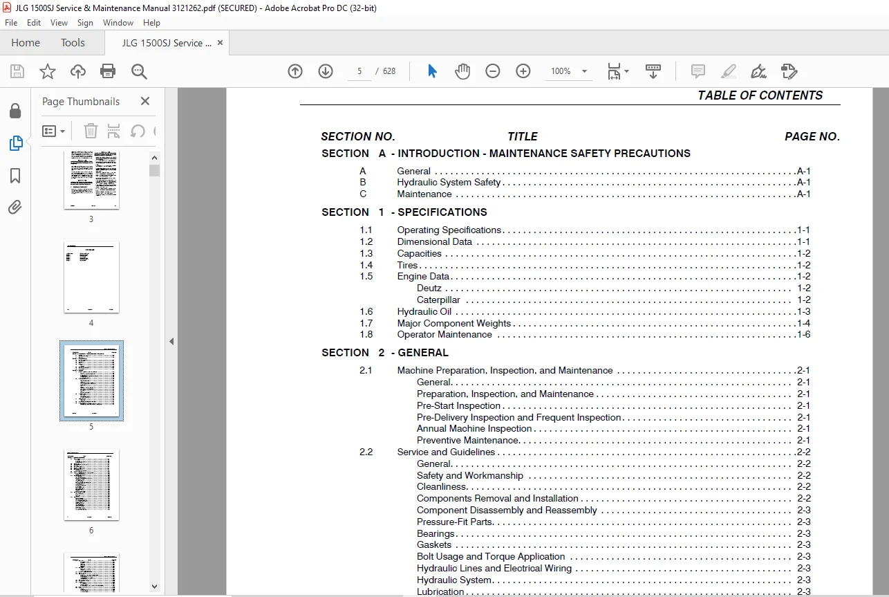
TABLE OF CONTENTS:
JLG 1500SJ Service & Maintenance Manual 3121262 – PDF DOWNLOAD
Section A INTRODUCTION – MAINTENANCE SAFETY PRECAUTIONS 3
A General 3
B Hydraulic System Safety 3
C Maintenance 3
Section 1 Specifications 21
1 1 Operating Specifications 21
1 2 Dimensional Data 21
1 3 Capacities 22
1 4 Tires 22
1 5 Engine Data 22
Deutz 22
Caterpillar 22
1 6 Hydraulic Oil 23
1 7 Major Component Weights 24
1 8 Operator Maintenance 26
Section 2 General 39
2 1 Machine Preparation, Inspection, and Maintenance 39
General 39
Preparation, Inspection, and Maintenance 39
Pre-Start Inspection 39
Pre-Delivery Inspection and Frequent Inspection 39
Annual Machine Inspection 39
Preventive Maintenance 39
2 2 Service and Guidelines 40
General 40
Safety and Workmanship 40
Cleanliness 40
Components Removal and Installation 40
Component Disassembly and Reassembly 41
Pressure-Fit Parts 41
Bearings 41
Gaskets 41
Bolt Usage and Torque Application 41
Hydraulic Lines and Electrical Wiring 41
Hydraulic System 41
Lubrication 41
Battery 41
Lubrication and Servicing 41
2 3 Lubrication and Information 41
Hydraulic System 41
Hydraulic Oil 42
Changing Hydraulic Oil 42
Lubrication Specifications 42
2 4 Cylinder Drift Test 42
Platform Drift 42
Cylinder Drift 43
2 5 Pins and Composite Bearing Repair Guidelines 43
2 6 Welding on JLG Equipment 43
Do the Following When Welding on JLG Equipment 43
Do NOT Do the Following When Welding on JLG Equipment 43
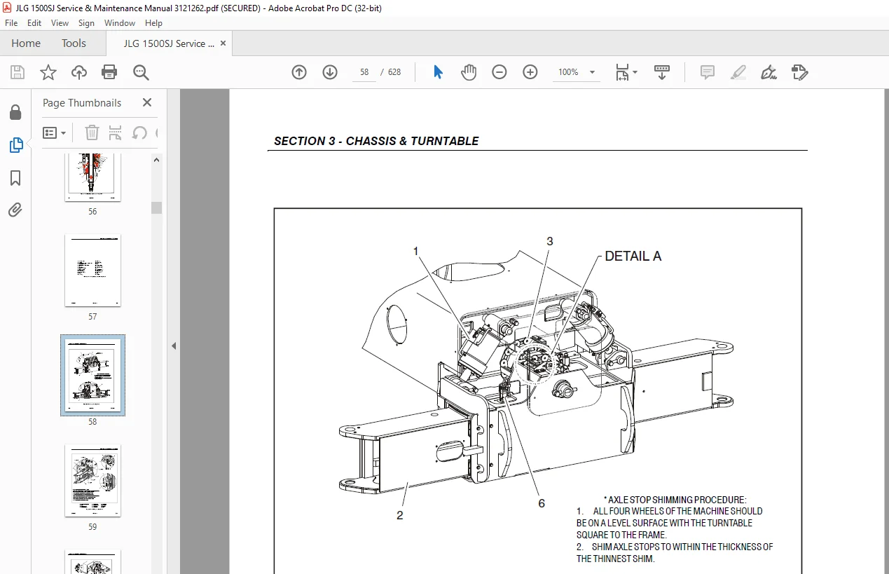
Section 3 Chassis & Turntable 49
3 1 Tires and Wheels 49
Tire Inflation 49
Tire Damage 49
Wheel and Tire Replacement 49
Wheel Installation 49
3 2 Extending Axles 50
3 3 Axle Limit Switch Adjustment Procedure 50
3 4 Drive System 51
3 5 Steering Control System 51
3 6 Drive/Steering Speed Control 52
3 7 Traction Control System 52
3 8 Drive Orientation System 52
Swing Envelope Service Mode 52
3 9 Oscillating Axle System 62
3 10 Oscillating Axle Bleeding Procedure and Lockout Test 62
Lockout Cylinder Bleeding 62
Oscillating Axle Lockout Test 63
3 11 Drive Hub – Bonfiglioli 64
Product Identification 64
Hydraulic Motor Installation 64
Installation of the Wheel Drive on the Machine 64
Start Up and Running In 64
General Information 65
Connecting the Brake 65
Filling-up the Gearbox with Lubricating Oil 65
Gearbox Disengagement 67
Maintenance Information 69
Changing the Lubricating oil 69
Troubleshooting 70
Disassembly Information 70
Disassembly Procedure 70
Inspection of Parts 78
Assembly 79
Final Test and Reinstallation 89
3 12 Drive Hub – Reggiana Riduttori 94
Symbol Nomenclature 94
Tools 94
Disassembly 99
Assembly 103
3 13 Swing Drive 109
Roll and Leak Testing 109
Tightening and Torquing Bolts 109
Motor Control Valve Disassembly 110
Motor and Brake Disassembly 111
Main Disassembly 112
Hub-Shaft Disassembly 113
Carrier Disassembly 114
Hub-Shaft Sub-Assembly 115
Carrier Sub-Assembly 116
Main Assembly 119
Motor and Brake Assembly 121
Motor Control Valve Assembly 122
3 14 Swing Brake 123
Pre-Installation Checks 123
Installation 124
Maintenance 124
Disassembly 124
Examination 124
Assembly 124
3 15 Swing Motor 126
Disassembly and inspection 126
Assembly 133
One Piece Stator Construction 140
3 16 Procedure For Setting Gear Backlash 141
3 17 Swing Drive Lubrication 142
3 18 Swing Bearing 143
Turntable Bearing Mounting Bolt Condition Check 143
Wear Tolerance 146
Turntable/Swing Bearing Removal 147
Turntable/Swing Bearing Installation 159
Swing Bearing Torque Values 166
3 19 Swing Speed Proportioning 167
3 20 Chassis Tilt Indicator System 167
3 21 Generator 168
Every 250 hours 168
Every 500 hours 168
Overload Protection 169
Inspecting Brushes, Replacing Brushes, and Cleaning Slip Rings 169
3 22 Auxiliary Power System 171
3 23 Engine 172
Glow Plugs 172
Checking Oil Level 172
Changing Engine Oil 173
Changing the Oil Filter 173
Replacing the Fuel Filter 174
Cleaning the Fuel Strainer 175
3 24 Deutz EMR 2 175
3 25 Bio Fuel in Deutz Engines 188
General 188
Bio Fuel 188
Biological Contamination In Fuels 189
3 26 CAT DGC DIAGNOSTIC SUPPORT AND TROUBLE CODE DEFINITIONS 190
List of Abbreviations in this Section 192
Diagnostic Trouble Codes 194
CAN 194
MIL Output 194
DTC 116- ECT Higher Than Expected Stage 1 195
DTC 117- ECT/CHT Low Voltage 196
DTC 118- ECT/CHT High Voltage 198
DTC 122- TPS1 Signal Voltage Low 200
DTC 123- TPS1 Signal Voltage High 202
DTC 217- ECT Higher Than Expected 2 204
DTC 219- RPM Higher Than Max Allowed Governed Speed 205
DTC 336- Crank Signal Input Noise 206
DTC 337- Loss of Crank Input Signal 208
DTC 521- Oil Pressure Sender/Switch High Pressure 209
DTC 524- Oil Pressure Low 210
DTC 562- Battery Voltage (VBat) Low 212
DTC 563- Battery Voltage (VBat) High 214
DTC 601- Microprocessor Failure – FLASH 216
DTC 604- Microprocessor Failure – RAM 218
DTC 606- Microprocessor Failure – COP 220
DTC 642- 5 Volt External Low Voltage 222
DTC 643- 5 Volt External High Voltage 223
DTC 1612- Microprocessor Failure – RTI 1 224
DTC 1613- Microprocessor Failure – RTI 2 225
DTC 1614- Microprocessor Failure – RTI 3 227
DTC 1615- Microprocessor Failure – A/D 229
DTC 1616- Microprocessor Failure – interrupt 231
DTC 1625- CAN J1939 Shutdown Request 233
DTC 1626- CAN J1939 Transmit (Tx) Fault 234
DTC 1627- CAN J1939 Receive (Rx) Fault 235
DTC 1628- CAN Address Conflict Failure 236
DTC 1629- J1939 TSC1 Message Reciept Loss 238
DTC 1652- TPS1 Loss of Communications 239
DTC 2111- Unable to Reach Lower TPS 240
DTC 2112- Unable to Reach Higher TPS 242
DTC 9999- Throttle Actuator Failsafe Spring Failure 243
DTC to SPN/FMI Table 244
3 27 Counterweight 245
Section 4 Boom & Platform 247
4 1 Boom Systems 247
Broken Cable Indicator System 247
Platform Control Enable System 247
Transport Position Sensing System 247
Beyond Transport – Drive Speed Cutback System 247
Drive/Steer – Boom Function Interlock System (CE ONLY) 250
Jib Stow System 250
Envelope Tracking System 250
Moment Control System 250
Boom Control System (BCS) Functional Check (Push to Test) System 251
4 2 Boom/Jib System Functionality 251
Main Lift/Jib Velocity Control 251
Jib Leveling During Automatic/Manual Envelope Control 251
Jib Lift Functionality 253
Jib Telescope Functionality 253
Jib Swing Functionality 253
Jib Swing Stow Sequence (Jib Pin Unlock) 253
Jib Swing Deploy Sequence (Jib Pin Lock) 255
Jib Lock Pin Lamp Operation 255
Swing/Axle Extend Retract Restrictions 256
Dual Capacity 256
Jib Control During Over/Under Moment 256
Boom Recovery Mode 256
4 3 Boom Removal and Installation 258
Removal 258
Installation 260
4 4 Boom Disassembly/Assembly & Cable Replacement 263
Disassembly 263
Assembly 281
4 5 Load Sensing Pin Removal and Installation 296
4 6 Jib 298
Removal 298
Installation 300
4 7 Boom Lubrication Application 305
4 8 Platform Leveling Cylinder 305
Removal 305
Installation 306
4 9 Jib Telescope Cylinder 307
Removal 307
Installation 309
4 10 Jib Lift Cylinder 310
Removal 310
Installation 311
4 11 Jib Straight Shimming Procedure 312
4 12 Boom Cleanliness Guidelines 314
4 13 Hose Routing 314
4 14 Powertrack Maintenance 318
One Piece Bracket Maintenance 318
Two Piece Bracket Maintenance 320
Snap Rings and Screws 321
4 15 Wire Rope 323
Inspection 323
Three Month Inspection 323
Seven Year Inspection 323
Replacement Criteria 323
4 16 Wire Rope Tensioning Adjustment 324
Boom Section Re-Positioning 324
Wire Rope Tensioning Procedure 326
4 17 Broken Boom Cable Proximity Switch 333
Adjusting the Proximity Switch 333
4 18 Electronic Platform Leveling 333
Description 333
Normal Operation 334
4 19 Rotary Actuator 335
Theory of Operation 335
Tools Required 336
Disassembly 337
Inspection 342
Assembly 343
Greasing Thrust Washers 347
Installing Counterbalance Valve 347
Testing the Actuator 347
Installation and Bleeding 349
Troubleshooting 350
4 20 Jib Rotator Torquing Procedure 351
Section 5 Hydraulics 353
5 1 Lubricating O-Rings in the Hydraulic System 353
Cup and Brush 353
Dip Method 354
Spray Method 354
Brush-on Method 354
5 2 Hydraulic Cylinders 355
Axle Extension Cylinder 355
Axle Lockout Cylinder 361
Jib Level Cylinder 367
Platform Level Cylinder 373
Boom Lift Cylinder 379
Jib Lift Cylinder 385
Jib Lock Cylinder 391
Steer Cylinder 394
Jib Telescope Cylinder 398
Main Boom Telescope Cylinder 402
5 3 Cylinder Length Sensor 408
Removal 408
Installation 410
5 4 Oil Sampling 421
Procedure 421
5 5 Pressure Setting Procedure 422
Set Up of the Function Pump 422
Adjustments made at the Main Valve Bank 423
Adjustments Made at the Frame Valve Bank 423
Adjustments Made at the Platform Valve Bank 428
Adjustments Made at the Jib Valve 429
5 6 Drive Pumps 432
Troubleshooting Procedure 432
Charge Pressure Relief Valve Adjustment 435
Mechanical Centering of Pump 436
Hydraulic Centering of Control Modules 436
High Pressure Relief Valve Adjustments 437
Removal and inspection of charge pump 437
Routine Maintenance 438
Removal and Installation of Shaft Seal 440
5 7 Function Pump 441
Spare Parts 441
Sealing the Drive Shaft 442
Disassembly and Assembly of the Complete Unit 443
Assembly 446
Adjustments 447
Tightening Torques 447
Pump Control Disassembly For Cleaning 449
5 8 Drive & Function Pump Start Up Procedures 451
Start-Up Procedure 451
Section 6 JLG Control System 453
6 1 JLG Control System Analyzer Kit Instructions 453
Introduction 453
To Connect the JLG Control System Analyzer 454
Using the Analyzer 454
Changing the Access Level of the Hand Held Analyzer 455
Adjusting Parameters Using the Hand Held Analyzer 456
Machine Setup 457
Level Vehicle Description 457
6 2 Machine Personality Settings and Function Speeds 465
6 3 Machine Orientation When Setting Function Speeds 470
Test Notes 470
6 4 CANbus Communications 471
6 5 Calibration Instructions 473
6 6 Control System Boom Sensors 489
Sensor #1 – Moment Pin 489
Sensor #2 – Main Boom Angle Sensors 489
Sensor #3 – Main Boom Length Sensor 491
Sensor #4 – Main Boom Cylinder Angle Sensor 491
Sensor #5 – Main Boom Transport Length Switch 491
Sensor #6 – Jib Level Angle Sensor 492
Sensor #7 – Jib Lock Pin Switch 492
Sensor #8 – Jib Stow Angle Sensor 492
Sensor #9 – Jib Lift Cylinder Angle Sensor 492
Sensor #10 – Dual Capacity / Jib Transport Length Switches 493
Sensor #11 – Platform Level Cylinder Angle Sensor 493
Sensor #12 – Platform Level Sensors 493
Sensor #13 – Rotary Turntable Angle Sensor 493
6 7 Jib Control Module 494
6 8 CAN Gateway 494
6 9 System Test 495
Test from the Platform 495
Test from the Ground Station 498
6 10 Calibrating Steer 513
6 11 Calibrating Drive 516
6 12 Electronic Platform Leveling 519
Platform Leveling Fault Warning 519
Fault Response 519
6 13 Calibrating Platform Level 520
STEP 1: SETTING THE PLATFORM VALVE MINIMUMS 520
STEP 2: BLEEDING THE PLATFORM VALVES 521
STEP 3: CALIBRATING THE PLATFORM LEVEL UP AND DOWN VALVE CRACKPOINTS 522
6 14 Calibrating Lift Crack Point 523
6 15 Calibrating Telescope Crack point 526
6 16 Calibrating Tilt Sensor 530
6 17 Jib Sensor Calibrations 532
Calibrating the Jib Level Up and Down Valve Crackpoints 541
6 18 Calibrating the Boom Sensors 543
Boom Control System Check Procedure 559
Section 7 Basic Electrical Information & Schematics 581
7 1 General 581
7 2 Multimeter Basics 581
Grounding 581
Backprobing 581
Min/Max 581
Polarity 581
Scale 581
Voltage Measurement 581
Resistance Measurement 582
Continuity Measurement 582
Current Measurement 583
7 3 Applying Silicone Dielectric Compound to Electrical Connections 583
Installation of Dielectric Grease 584
Deutsch HD, DT, DTM, DRC Series 584
AMP Seal 584
AMP Mate-N-Lok 585
DIN Connectors 585
Exclusions 585
7 4 AMP Connector 587
Assembly 587
Disassembly 589
Wedge Lock 589
Service – Voltage Reading 589
7 5 Deutsch Connectors 591
DT/DTP Series Assembly 591
DT/DTP Series Disassembly 591
HD30/HDP20 Series Assembly 592
HD30/HDP20 Series Disassembly 592
Contact us: [email protected]
PLEASE NOTE:
- This is the SAME exact manual used by your dealers to fix your vehicle.
- The same can be yours in the next 2-3 mins as you will be directed to the download page immediately after paying for the manual.
- Any queries / doubts regarding your purchase, please feel free to contact [email protected]
S.M