JLG 1044C-54 Telehandler Parts Manual – PDF DOWNLOAD
Original price was: $90.00.$21.95Current price is: $21.95.
JLG 1044C-54 Telehandler Parts Manual – PDF DOWNLOAD
S/N 0160009654 & After
including 0160008714
31200069
Description
JLG 1044C-54 Telehandler Parts Manual – PDF DOWNLOAD
FILE DETAILS:
JLG 1044C-54 Telehandler Parts Manual – PDF DOWNLOAD
Format: PDF
Language: English
Brand: JLG GRADALL
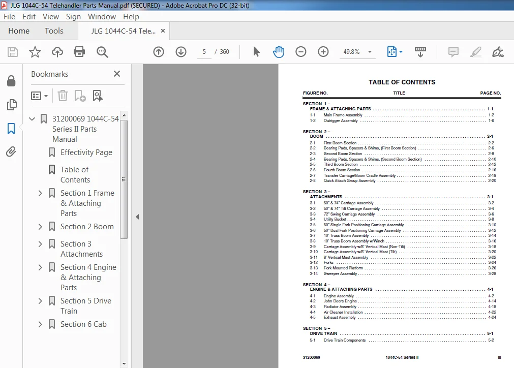
TABLE OF CONTENTS:
JLG 1044C-54 Telehandler Parts Manual – PDF DOWNLOAD
FIGURE NO. TITLE PAGE NO.
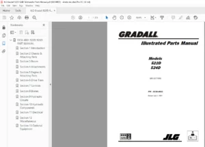
31200069 1044C-54 Series II iii
SECTION 1 –
FRAME & ATTACHING PARTS 1-1
1-1 Main Frame Assembly 1-2
1-2 Outrigger Assembly 1-6
SECTION 2 –
BOOM 2-1
2-1 First Boom Section 2-2
2-2 Bearing Pads, Spacers & Shims, (First Boom Section) 2-6
2-3 Second Boom Section 2-8
2-4 Bearing Pads, Spacers & Shims, (Second Boom Section) 2-10
2-5 Third Boom Section 2-12
2-6 Fourth Boom Section 2-16
2-7 Transfer Carriage/Boom Cradle Assembly 2-18
2-8 Quick Attach Group Assembly 2-20
SECTION 3 –
ATTACHMENTS 3-1
3-1 50” & 74” Carriage Assembly 3-2
3-2 50” & 74” Tilt Carriage Assembly 3-4
3-3 72” Swing Carriage Assembly 3-6
3-4 Utility Bucket 3-8
3-5 50” Single Fork Positioning Carriage Assembly 3-10
3-6 50” Dual Fork Positioning Carriage Assembly 3-12
3-7 10’ Truss Boom Assembly 3-14
3-8 10’ Truss Boom Assembly w/Winch 3-16
3-9 Carriage Assembly w/8’ Vertical Mast (Non-Tilt) 3-18
3-10 Carriage Assembly w/8’ Vertical Mast (Tilt) 3-20
3-11 8’ Vertical Mast Assembly 3-22
3-12 Forks 3-24
3-13 Fork Mounted Platform 3-26
3-14 Sweeper Assembly 3-28
SECTION 4 –
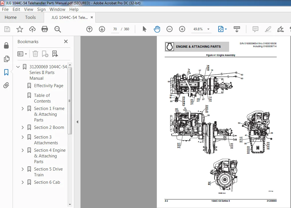
ENGINE & ATTACHING PARTS 4-1
4-1 Engine Assembly 4-2
4-2 John Deere Engine 4-14
4-3 Radiator Assembly 4-18
4-4 Air Cleaner Installation 4-22
4-5 Exhaust Assembly 4-24
SECTION 5 –
DRIVE TRAIN 5-1
5-1 Drive Train Components 5-2
5-2 Front Axle Assembly 5-4
5-3 Front Axle – Input 5-6
5-4 Front Axle – Limited Slip Differential 5-10
5-5 Front Axle – Axle Casing 5-12
5-6 Front Axle – M-Disc Brake 5-14
5-7 Front Axle – Brake 5-18
5-8 Front Axle – Joint Housing 5-20
5-9 Front Axle – Planetary Drive 5-22
5-10 Rear Axle Assembly 5-24
5-11 Rear Axle – Input 5-26
5-12 Rear Axle – Differential 5-30
5-13 Rear Axle – Axle Casing 5-32
5-14 Rear Axle – M-Disc Brake 5-34
5-15 Rear Axle – Brake 5-38
5-16 Rear Axle – Joint Housing 5-40
5-17 Rear Axle – Planetary Drive 5-44
5-18 ZF Transmission – Converter & Input 5-46
5-19 ZF Transmission – Gearbox Housing 5-48
5-20 ZF Transmission – Reversing Gear KV 5-50
5-21 ZF Transmission – Reversing Gear KR 5-52
5-22 ZF Transmission – Coupling Group K1 5-54
5-23 ZF Transmission – Coupling Group K2 5-56
5-24 ZF Transmission – Coupling Group K3 5-58
5-25 ZF Transmission – Coupling Group K4 5-60
5-26 ZF Transmission – Output 5-62
5-27 ZF Transmission – Control Unit 5-64
5-28 ZF Transmission – Gearshift System 5-66
5-29 ZF Transmission – Oil Pump, Filter & Dipstick 5-70
5-30 Drive Shaft 5-72
5-31 Tires and Rims 5-74
SECTION 6 –
CAB 6-1
6-1 Operators Compartment Assembly 6-2
6-2 Cab Enclosure Kit 6-4
6-3 Windshield Wiper Assembly 6-6
6-4 Windshield Assembly 6-8
6-5 Window Assembly 6-10
6-6 Door Assembly 6-12
6-7 Insulation Installation 6-14
6-8 Instrument Panel Assembly 6-16
6-9 Operator’s Seat 6-18
6-10 Heater & Air Conditioning System 6-22
6-11 Valve Plate Components Assembly
CONTROLS 7-1
7-1 Joystick Control Valve 7-2
7-2 3 Handle Single Axis Control Valve Assembly 7-4
7-3 Steer Column Assembly 7-6
7-4 Brake Valve Assembly 7-8
7-5 Accelerator Pedal 7-10
SECTION 8 –
HYDRAULIC CIRCUITS 8-1
8-1 Pump, Suction – Return 8-2
8-2 Boom Hydraulic Cylinder 8-4
8-3 Hoist & Rear Carriage Tilt 8-6
8-4 Second Auxiliary Circuit 8-8
8-5 Transfer Cylinder 8-10
8-6 Outrigger Cylinder & Joystick 8-12
8-7 Frame Tilt & Rear Axle Stabilizer 8-14
8-8 Steering Cylinder 8-18
8-9 Joystick Control Circuit 8-20
8-10 Service Brake Circuit 8-22
8-11 Park Brake Circuit 8-24
8-12 Test Port Hydraulic Assembly 8-26
SECTION 9 –
HYDRAULIC COMPONENTS 9-1
9-1 Front Carriage Tilt Cylinder 9-2
9-2 Rear Carriage Tilt Cylinder 9-4
9-3 Frame Tilt Cylinder 9-6
9-4 Hoist Cylinder 9-8
9-5 Boom Extension Cylinder 9-10
9-6 Transfer Cylinder 9-12
9-7 Outrigger Cylinder 9-14
9-8 Rear Stabilizer Cylinder 9-16
9-9 Steering Cylinder 9-18
9-10 Hydraulic Control Valve Assembly – Mid-Inlet 9-20
9-11 Valve Section Assembly – Boom Hoist/Boom Extension 9-22
9-12 Valve Section Assembly – Fork Tilt/Outrigger/Transfer/Auxiliary/Frame Tilt 9-24
9-13 Relief Valve Assembly 9-26
9-14 Relief Valve Assembly – Mid-Inlet 9-28
9-15 Tandem Pump 9-30
9-16 Accumulator Charge Valve 9-32
9-17 6-Port Circuit Selector Valve Assembly 9-34
9-18 Hydraulic Return Line Filter Assembly 9-36
9-19 Pressure Filter Assembly
9-20 Inline Filter Assembly 9-40
9-21 Accumulator Assembly 9-42
9-22 Rear Axle Stabilizer Control Valve, (under cab) 9-44
9-23 Rear Axle Stabilizer Valve, (on rear axle) 9-46
9-24 Fuel/Hydraulic Tank Assy 9-48
9-25 Boom Extend Lockout Valve Assembly 9-50
9-26 Park Brake Valve Assembly 9-52
SECTION 10 –
ELECTRICAL 10-1
10-1 Frame Harness Installation 10-2
10-2 Outrigger/Boom Extend Lockout Harness Installation 10-6
10-3 Engine Electrical Group 10-8
10-4 Transmission Harness Installation 10-10
10-5 Operator’s Compartment Electrical Group Installation 10-12
10-6 Fuses, Relays & Buzzer Mounting Panel 10-14
SECTION 11 –
DECALS 11-1
11-1 Decal Group 11-2
SECTION 12 –
OPTIONS 12-1
12-1 Worklight Option Installation 12-2
12-2 Roadway Light Option Installation 12-8
12-3 Strobe/Rotating Beacon Light Option Installation 12-16
12-4 Tilting Carriage Cylinder 12-20
12-5 Tower Cylinder 12-22
12-6 Fork Positioning Cylinder 12-24
12-7 Lockable Engine Side Panels Option 12-26
12-8 Battery Cold Start Option 12-28
SECTION 13 –
RECOMMENDED SPARE PARTS 13-1
SECTION 14 – PART NUMBER INDEX
JLG 1044C-54 TELEHANDLER PARTS MANUAL – PDF DOWNLOAD:
IMAGES PREVIEW OF THE MANUAL:
PLEASE NOTE:
- This is the same manual used by the DEALERSHIPS to SERVICE your vehicle.
- The manual can be all yours – Once payment is complete, you will be taken to the download page from where you can download the manual. All in 2-5 minutes time!!
- Need any other service / repair / parts manual, please feel free to contact us at heydownloadss @gmail.com . We may surprise you with a nice offer
Jakob –
Very efficient