JLG 1532E2 1932E2 2032E2 2632E2 2646E2 3246E2 Service & Maintenance Manual 3120855 – PDF DOWNLOAD
$25.95
JLG 1532E2 1932E2 2032E2 2632E2 2646E2 3246E2 Service & Maintenance Manual 3120855 – PDF DOWNLOAD
Description
JLG 1532E2 1932E2 2032E2 2632E2 2646E2 3246E2 Service & Maintenance Manual 3120855 – PDF DOWNLOAD
FILE DETAILS:
JLG 1532E2 1932E2 2032E2 2632E2 2646E2 3246E2 Service & Maintenance Manual 3120855 – PDF DOWNLOAD
Language : English
Pages : 80
Downloadable : Yes
File Type : PDF
DESCRIPTION:
JLG 1532E2 1932E2 2032E2 2632E2 2646E2 3246E2 Service & Maintenance Manual 3120855 – PDF DOWNLOAD
GENERAL
This section contains the general safety precautions which must be observed during maintenance of the aerial platform. It is of utmost importance that maintenance personnel pay strict attention to these warnings and precautions to avoid possible injury to themselves or others, or damage to the equipment. A maintenance program must be followed to ensure that the machine is safe to operate.
- The specific precautions to be observed during maintenance are inserted at the appropriate point in the manual. These precautions are, for the most part, those that apply when servicing hydraulic and larger machine component parts.
- Your safety, and that of others, is the first consideration when engaging in the maintenance of equipment. Always be conscious of weight. Never attempt to move heavy parts without the aid of a mechanical device.
- Do not allow heavy objects to rest in an unstable position. When raising a portion of the equipment, ensure that adequate support is provided.
B HYDRAULIC SYSTEM SAFETY
It should be noted that the machines hydraulic systems operate at extremely high potentially dangerous pressures. Every effort should be made to relieve any system pressure prior to disconnecting or removing any portion of the system. Relieve system pressure by cycling the applicable control several times with the engine stopped and ignition on, to direct any line pressure back into the reservoir. Pressure feed lines to system components can then be disconnected with minimal fluid loss.
MAINTENANCE
- NO SMOKING IS MANDATORY. NEVER REFUEL DURING ELECTRICAL STORMS. ENSURE THAT FUEL CAP IS CLOSED AND SECURE AT ALL OTHER TIMES.
- REMOVE ALL RINGS, WATCHES AND JEWELRY WHEN PERFORMING ANY MAINTENANCE.
- DO NOT WEAR LONG HAIR UNRESTRAINED, OR LOOSE-FITTING CLOTHING AND NECKTIES WHICH ARE APT TO BECOME CAUGHT ON OR ENTANGLED IN EQUIPMENT.
- OBSERVE AND OBEY ALL WARNINGS AND CAUTIONS ON MACHINE AND IN SERVICEMANUAL.
- KEEP OIL, GREASE, WATER, ETC. WIPED FROM STANDING SURFACES AND HAND HOLDS.
- USE CAUTION WHEN CHECKING A HOT, PRESSURIZED COOLANT SYSTEM.
- NEVER WORK UNDER AN ELEVATED BOOM UNTIL BOOM HAS BEEN SAFELY RESTRAINED FROM ANY MOVEMENT BY BLOCKING OR OVERHEAD SLING, OR BOOM SAFETY PROP HAS BEEN ENGAGED.
- BEFORE MAKING ADJUSTMENTS, LUBRICATING OR PERFORMING ANY OTHER MAINTENANCE, SHUT OFF ALL POWER CONTROLS.
- BATTERY SHOULD ALWAYS BE DISCONNECTEDDURING REPLACEMENT OF ELECTRICAL COMPONENTS
- KEEP ALL SUPPORT EQUIPMENT AND ATTACHMENTS STOWED IN THEIR PROPER PLACE.
- USE ONLY APPROVED, NONFLAMMABLE CLEANING SOLVENTS.
IMAGES PREVIEW OF THE MANUAL:
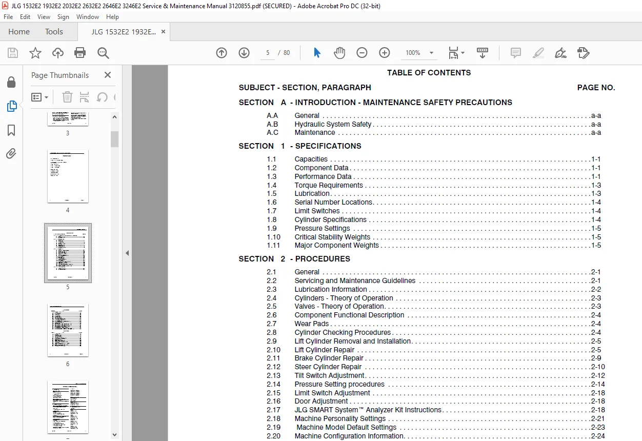
TABLE OF CONTENTS:
JLG 1532E2 1932E2 2032E2 2632E2 2646E2 3246E2 Service & Maintenance Manual 3120855 – PDF DOWNLOAD
Section A INTRODUCTION – MAINTENANCE SAFETY PRECAUTIONS 3
A A General 3
A B Hydraulic System Safety 3
A C Maintenance 3
Section 1 specifications 7
1 1 Capacities 7
Hydraulic Oil Tank 7
Hydraulic System (Including Tank) 7
1 2 Component Data 7
Hydraulic Pump/Electric Motor Assembly 7
Battery Charger 7
Batteries (4) 7
Steer/Drive System 7
Hydraulic Filter – Inline 7
Platform Size 7
1 3 Performance Data 7
Travel Speed 7
Gradeability 8
Inside Turning Radius 8
Lift (No Load in Platform) 8
Platform Capacity 8
Manual Platform Extension Capacity 8
Machine Weight 8
Wheelbase 8
Platform Height (Elevated) 8
Platform Height (Stowed) 8
Machine Height (Stowed) 8
Machine Length 8
Machine Width 8
Ground Clearance 9
Maximum Tire Load 9
Maximum Bearing Pressure 9
1 4 Torque Requirements 9
1 5 Lubrication 9
Hydraulic Oil 9
Lubrication Specifications 9
1 6 Serial Number Locations 10
1 7 Limit Switches 10
1 8 Cylinder Specifications 10
1 9 Pressure Settings 11
Pressure Settings for Non Proportional Control Machines 11
2632E2/2646E2/3246E2 – 165 bar 11
Pressure Settings for Proportional Control Machines 11
1 10 Critical Stability Weights 11
1 11 Major Component Weights 11
Section 2 procedures 13
2 1 General 13
2 2 Servicing and Maintenance Guidelines 13
General 13
Safety and Workmanship 13
Cleanliness 13
Components Removal and Installation 13
Component Disassembly and Reassembly 13
Pressure Washing 13
Pressure-Fit Parts 14
Bearings 14
Gaskets 14
Bolt Usage and Torque Application 14
Hydraulic Lines and Electrical Wiring 14
Hydraulic System 14
Lubrication 14
Batteries 14
Lubrication and Servicing 14
2 3 Lubrication Information 14
Hydraulic System 14
Hydraulic Oil 15
Changing Hydraulic Oil 15
Lubrication Specifications 15
2 4 Cylinders – Theory of Operation 15
2 5 Valves – Theory of Operation 15
Solenoid Control Valves (Bang-Bang) 15
Relief Valves 16
Crossover Relief Valves 16
2 6 Component Functional Description 16
Hydraulic Pump 16
2 7 Wear Pads 16
Sliding Pads 16
2 8 Cylinder Checking Procedures 16
Cylinder w/o Holding Valves – Brake Cylinder and Steer Cylinder 16
Cylinders w/Single Holding Valves – Lift Cylinder 17
2 9 Lift Cylinder Removal and Installation 17
Lift Cylinder Removal 17
Lift Cylinder Installation 17
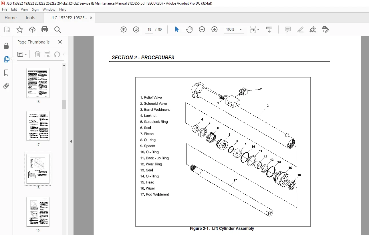
2 10 Lift Cylinder Repair 17
Disassembly 17
Cleaning and Inspection 19
Assembly 19
2 11 Brake Cylinder Repair 21
Disassembly 21
Cleaning and Inspection 22
Assembly 22
2 12 Steer Cylinder Repair 22
Disassembly 22
Cleaning and Inspection 23
Assembly 24
2 13 Tilt Switch Adjustment 24
Manual Adjustment 24
Voltmeter Adjustment 25
2 14 Pressure Setting procedures 26
Lift Relief for Non Proportional Control Machines 26
Steer Adjustment for Non Proportional Control Machines 26
Main Relief Pressure Switch for Non Proportional Control Machines 27
Lift Relief Adjustments for Proportional Control Machines 27
Steer Adjustment for Proportional Control Machines 27
Main Relief and High Drive Pressure Switch for Proportional Control Machines 27
2 15 Drive Motor (Sauer Danfoss) 30
Dismantling 30
Assembly 31
2 16 Drive Motor (Rexroth) 31
Disassembly 31
Assembly 31
2 17 Drive Motor (Parker) 32
Disassembly and inspection 32
Assembly 39
Torque the two shuttle valve plug assemblies (21) in end cover assembly to 9-12 ft lbs (12-16 N m) if cover is so equipped To 45
2 18 Limit Switch Adjustment 47
Platform Limit Switch 47
2 19 Door Adjustment 47
2 20 JLG SMART System™ Analyzer Kit Instructions 47
INTRODUCTION 48
To Connect the Hand Held Analyzer: 48
Using the Analyzer: 48
Changing the Access Level of the Hand Held Analyzer: 49
Adjusting Configuration Using the Hand Held Analyzer on All 1600286 Controllers: 49
2 21 Machine Personality Settings 52
2 22 Machine Model Default Settings 53
2 23 Machine Configuration Information 54
2 24 Jlg Smart System™ Help Messages and Flash Codes 56
2 25 Analyzer Menu Structure 59
2 26 Preventive Maintenance and Inspection Schedule 65
Section 3 Troubleshooting 67
3 1 General 67
3 2 Troubleshooting Information 67
3 3 Hydraulic Circuit Checks 67
Customer Support: [email protected]
PLEASE NOTE:
- This is the SAME manual used by the dealers to troubleshoot any faults in your vehicle. This can be yours in 2 minutes after the payment is made.
- Contact us at [email protected] should you have any queries before your purchase or that you need any other service / repair / parts operators manual.
S.M