JLG 1930ES 2030ES 2630ES 2646ES 3246ES Service & Maintenance Manual 3121166 – PDF DOWNLOAD
$25.95
JLG 1930ES 2030ES 2630ES 2646ES 3246ES Service & Maintenance Manual 3121166 – PDF DOWNLOAD
Description
JLG 1930ES 2030ES 2630ES 2646ES 3246ES Service & Maintenance Manual 3121166 – PDF DOWNLOAD
FILE DETAILS:
JLG 1930ES 2030ES 2630ES 2646ES 3246ES Service & Maintenance Manual 3121166 – PDF DOWNLOAD
Language : English
Pages : 212
Downloadable : Yes
File Type : PDF
DESCRIPTION:
JLG 1930ES 2030ES 2630ES 2646ES 3246ES Service & Maintenance Manual 3121166 – PDF DOWNLOAD
GENERAL
This section contains the general safety precautions which must be observed during maintenance of the aerial platform. It is of utmost importance that maintenance personnel pay strict attention to these warnings and precautions to avoid possible injury to themselves or others, or damage to the equipment. A maintenance program must be followed to ensure that the machine is safe to operate.
- The specific precautions to be observed during maintenance are inserted at the appropriate point in the manual. These precautions are, for the most part, those that apply when servicing hydraulic and larger machine component parts.
- Your safety, and that of others, is the first consideration when engaging in the maintenance of equipment. Always be conscious of weight. Never attempt to move heavy parts without the aid of a mechanical device.
- Do not allow heavy objects to rest in an unstable position. When raising a portion of the equipment, ensure that adequate support is provided.
B HYDRAULIC SYSTEM SAFETY
It should be noted that the machines hydraulic systems operate at extremely high potentially dangerous pressures. Every effort should be made to relieve any system pressure prior to disconnecting or removing any portion of the system. Relieve system pressure by cycling the applicable control several times with the engine stopped and ignition on, to direct any line pressure back into the reservoir. Pressure feed lines to system components can then be disconnected with minimal fluid loss.
MAINTENANCE
- NO SMOKING IS MANDATORY. NEVER REFUEL DURING ELECTRICAL STORMS. ENSURE THAT FUEL CAP IS CLOSED AND SECURE AT ALL OTHER TIMES.
- REMOVE ALL RINGS, WATCHES AND JEWELRY WHEN PERFORMING ANY MAINTENANCE.
- DO NOT WEAR LONG HAIR UNRESTRAINED, OR LOOSE-FITTING CLOTHING AND NECKTIES WHICH ARE APT TO BECOME CAUGHT ON OR ENTANGLED IN EQUIPMENT.
- OBSERVE AND OBEY ALL WARNINGS AND CAUTIONS ON MACHINE AND IN SERVICEMANUAL.
- KEEP OIL, GREASE, WATER, ETC. WIPED FROM STANDING SURFACES AND HAND HOLDS.
- USE CAUTION WHEN CHECKING A HOT, PRESSURIZED COOLANT SYSTEM.
- NEVER WORK UNDER AN ELEVATED BOOM UNTIL BOOM HAS BEEN SAFELY RESTRAINED FROM ANY MOVEMENT BY BLOCKING OR OVERHEAD SLING, OR BOOM SAFETY PROP HAS BEEN ENGAGED.
- BEFORE MAKING ADJUSTMENTS, LUBRICATING OR PERFORMING ANY OTHER MAINTENANCE, SHUT OFF ALL POWER CONTROLS.
- BATTERY SHOULD ALWAYS BE DISCONNECTEDDURING REPLACEMENT OF ELECTRICAL COMPONENTS
- KEEP ALL SUPPORT EQUIPMENT AND ATTACHMENTS STOWED IN THEIR PROPER PLACE.
- USE ONLY APPROVED, NONFLAMMABLE CLEANING SOLVENTS.
IMAGES PREVIEW OF THE MANUAL:
TABLE OF CONTENTS:
JLG 1930ES 2030ES 2630ES 2646ES 3246ES Service & Maintenance Manual 3121166 – PDF DOWNLOAD
Service & Maintenance Manual 1
Section A Introduction – Maintenance Safety Precautions 3
A A General 3
A B Hydraulic System Safety 3
A C Maintenance 3
Section 1 Specifications 13
1 1 Specifications 13
Capacities 14
Fluid Capacities 14
Tires 15
Batteries 15
Motors 15
Battery Charger 15
Travel Speed 16
Lift Speed (No Load in Platform) 16
Model Dimensions 17
1 2 Torque Requirements 18
1 3 Lubrication 18
Hydraulic Oil 18
1 4 Limit Switches 19
Tilt Alarm 19
High Drive Speed Cutout 19
Pressure Settings 19
1 5 Cylinder Specifications 20
1 6 Major Component Weights 20
1 7 Critical Stability Weights 20
1 8 Torque ChartS 21
Section 2 General 29
2 1 Machine Preparation, Inspection, and Maintenance 29
General 29
Preparation, Inspection, and Maintenance 29
Pre-Start Inspection 29
Pre-Delivery Inspection and Frequent Inspection 29
Annual Machine Inspection 29
Preventative Maintenance 29
2 2 Service and Guidelines 30
General 30
Safety and Workmanship 30
Cleanliness 30
Components Removal and Installation 30
Component Disassembly and Reassembly 30
Pressure-Fit Parts 31
Bearings 31
Gaskets 31
Bolt Usage and Torque Application 31
Hydraulic Lines and Electrical Wiring 31
Hydraulic System 31
Lubrication 31
Battery 31
Lubrication and Servicing 31
2 3 Lubrication and Information 32
Hydraulic System 32
Hydraulic Oil 32
Changing Hydraulic Oil 32
Lubrication Specifications 32
2 4 Cylinder Drift Test 33
Platform Drift 33
Cylinder Drift 33
2 5 Pins and Composite Bearing Repair Guidelines 33
2 6 Preventive Maintenance and Inspection Schedule 34
Section 3 Chassis & Scissor Arms 37
3 1 Diagnostic Port 37
3 2 MDI (Multifunction Digital Indicator) and brake release 37
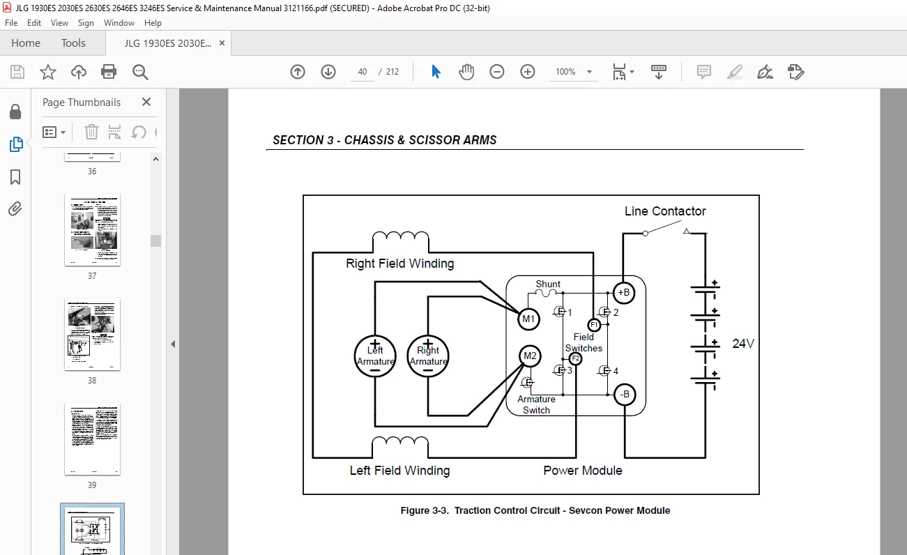
3 3 Traction System 39
Theory of Operation 39
3 4 Torque Hub 41
Roll Test 41
Leak Test 41
Oil Check/Fill Procedure 41
Manual Disengage Procedure 42
Manual Disengage Procedure 43
Manual Disengage Procedure 44
Motor and Brake Disassembly 45
Motor Disassembly 46
Drive Motor Removal 47
Main Gearbox Disassembly 48
Input Carrier Disassembly 49
Hub Disassembly 50
Spindle Disassembly 51
Spindle Sub-Assembly 52
Hub Sub-Assembly 53
Input Carrier Sub-Assembly 54
Main Gearbox Assembly 55
Motor and Brake Assembly 57
Motor Assembly 59
Motor Assembly 60
Tightening and Torquing Bolts 61
Assembly Tools 61
3 5 Electric Drive Motor 62
Disassembly 62
Replacing Motor Bearing 62
Inspecting Motor Brushes 62
Replacing Motor Brushes 62
Replacing the Motor Cable 62
Reassembling the Motor 63
Motor Maintenance 64
Disassembly 65
Inspection and Service 66
Reassembly 66
3 6 Electric Drive Motor 68
Drive Motor Troubleshooting 69
Drive Motor Disassembly 69
Drive Motor Inspection and Service 69
Drive Motor Reassembly 70
Drive Motor Servicing Guidelines 71
3 7 Drive Motor Electrical Evaluation 72
Servicing Guidelines 72
Common Traction System Difficulties 73
3 8 Power Module – Sevcon 74
Power Module Electrical Evaluation 75
3 9 Power Module – ZAPI 76
ZAPI Power Module Electrical Evaluation 77
3 10 Battery Removal 78
Battery Maintenance and Safety Practices 79
3 11 Battery Charger 79
Battery Charger Maintenance 80
Battery Charger Troubleshooting 81
3 12 Battery Charger/Inverter (Option) 84
Battery Charger/Inverter Troubleshooting 85
3 13 Drive Motor Cable Routing 86
3 14 Pothole Switch Replacement 91
Rotary Angle Sensor Replacement 95
3 15 Ground Control Station 95
Printed Circuit Board (PCB) Replacement 95
Tilt Sensor Replacement 96
3 16 Arms and Platform Positioning and Support 98
3 17 Platform Removal 99
3 18 Scissor Arms Removal 99
3 19 Platform Control Station 101
Joystick Controller 102
Section 4 Hydraulics 103
4 1 Cylinders – Theory of Operation 103
4 2 Valves – Theory of Operation 103
Solenoid Control Valves (Bang-Bang) 103
Relief Valves 103
Crossover Relief Valves 103
Proportional Valve 103
Manual Descent Valve 103
4 3 Cylinder Checking Procedure 104
Cylinders Without Counterbalance Valves and Steer Cylinder 104
4 4 Lift Pressure Setting Procedure 104
4 5 Hydraulic Oil Fill 105
Oil Check Procedure 105
Slide Block Lubrication 106
4 6 Lift Cylinder Removal 106
4 7 Pump/Motor 108
Pump Motor Electrical Evaluation 109
Pump Removal 110
Motor Removal 112
4 8 Cylinder Repair 113
Disassembly 113
Steer Cylinder Piston Removal – Cyl p/n- 1684456 114
Cleaning and Inspection 114
Assembly 115
Section 5 JLG Control System 121
5 1 Hand Held Analyzer 121
To Connect the Hand Held Analyzer: 121
Using the Analyzer: 122
Changing the Access Level of the Hand Held Analyzer: 123
Adjusting Parameters Using the Hand Held Analyzer 124
Machine Setup 124
5 2 Tilt Sensor Calibration 125
Ground Module Software Version 1 5 125
Ground Module Software Version 1 4 125
Failure Troubleshooting for The Field 126
5 3 Tilt Sensor Electrical Evaluation 126
5 4 Elevation Angle Sensor Electrical Evaluation 126
Tilt vs Allowed Height Evaluation 127
5 5 Elevation Sensor Calibration 128
5 6 Updating Software 128
5 7 Troubleshooting 129
Analyzer Flow Chart 142
5 8 Machine Model Adjustment – SEVCON – 1600346 Power Module 145
5 9 Machine Model Adjustment – ZAPI – 1001092456 Power Module 146
5 10 Machine Configuration Programming Information – SEVCON – 1600346 147
5 11 Machine Configuration Programming Information – ZAPI – 1001092456 148
Section 6 Diagnostic Trouble Codes 149
6 1 Introduction 149
6 2 DTC Index 149
6 3 DTC Check Tables 152
0-0 Help Comments 152
2-1 Power-Up 153
2-2 Platform Controls 153
2-3 Ground Controls 155
2-5 Function Prevented 155
3-1 Line Contactor Open Circuit 157
3-2 Line Contactor Short Circuit 157
3-3 Ground Output Driver 158
4-2 Thermal Limit (SOA) 160
4-4 Battery Supply 161
6-6 Communication 161
6-7 Accessory 163
7-7 Electric Motor 163
8-1 Tilt Sensor 165
8-2 Platform Load Sense 165
9-9 Hardware 165
Section 7 General Electrical Information & Schematics 169
7 1 General 169
7 2 Multimeter Basics 169
Grounding 169
Backprobing 169
Min/Max 169
Polarity 169
Scale 169
Continuity Measurement Over Long Distances 172
Requirements: 172
Procedure 172
7 3 Applying Silicone Dielectric Compound To Amp Connectors 173
Assembly 174
Disassembly 175
Wedge Lock 176
Service – Voltage Reading 177
7 4 Working With Deutsch Connectors 178
DT/DTP Series Assembly 178
DT/DTP Series Disassembly 178
HD30/HDP20 Series Assembly 178
HD30/HDP20 Series Disassembly 179
7 5 Switches 180
Basic check 180
Limit Switches 180
Automatic Switches 180
Switch Wiring – Low Side, High Side 181
7 6 Circuit Boards: Inputs and Outputs 181
7 7 Electrical Schematics and Layouts 186
Electrical Schematic – 1870164G – Sheet 1 of 2 186
Electrical Schematic – 1870164G – Sheet 2 of 2 187
Electrical Schematic – 1870205B – Sheet 1 of 2 188
Electrical Schematic – 1870205B – Sheet 2 of 2 189
Electrical Schematic – Sheet 1 of 2 (Machines with MDI) 190
Electrical Schematic – Sheet 2 of 2 (Machines with MDI) 191
Inverter/Charger Schematic 192
Electrical Components – Sheet 1 of 2 200
Electrical Components – Sheet 2 of 2 201
Electrical Components – Sheet 1 of 2 202
Electrical Components – Sheet 2 of 2 203
Electrical Components – Sheet 1 of 2 204
Electrical Components – Sheet 2 of 2 205
Electrical Components – Sheet 1 of 2 (Machines with MDI) 206
Electrical Components – Sheet 2 of 2 (Machines with MDI) 207
7 8 Hydraulic Schematic 210
Hydraulic Schematic – 2792599C 210
Need help? Contact: [email protected]
PLEASE NOTE:
- This is the SAME exact manual used by your dealers to fix your vehicle.
- The same can be yours in the next 2-3 mins as you will be directed to the download page immediately after paying for the manual.
- Any queries / doubts regarding your purchase, please feel free to contact [email protected]
S.M