★ TRUSTED BY 321,897+ PROFESSIONALS WORLDWIDE
🏢
Trusted Business
Verified & Licensed
🛡️
Virus Free Files
100% Safe Downloads
🔒
Secure Payment
SSL Protected
Instant Delivery
Available Immediately
Sale!

JLG 3369LE 4069LE M3369 M4069 Illustrated Parts Manual 3121640 Rev P

Original price was: $34.95.Current price is: $19.95.

Complete JLG illustrated parts manual for 3369LE, 4069LE, M3369 and M4069 scissor lifts. Document 3121640 Rev P with exploded views, part numbers and breakdowns for every major assembly.

SKU: JLG-3121640-P-IPM-HD Category: Tags: , , , Vendor: Generator Manuals
Instant PDF Download
Available immediately
💾
Save to Your Device
Download & keep forever
🛡️
Antivirus Scanned
100% virus-free
🌍
Trusted Worldwide
175,000+ customers

Description

JLG 3369LE 4069LE M3369 M4069 Illustrated Parts Manual – 3121640 Rev P

This is the complete JLG Illustrated Parts Manual covering the 3369LE, 4069LE, M3369 and M4069 scissor lift models. Published under document number 3121640 Rev P, this manual gives you the exploded-view parts breakdowns, item numbers and part numbers needed to identify and order the correct components for your machine.

Every major assembly is covered with illustrated figures and matching parts lists. Whether you are rebuilding a drive hub, replacing a lift cylinder seal kit, tracking down a hydraulic fitting or ordering a replacement decal, the exact part number is listed against its illustration callout.

File Details

  • Manual type: Illustrated Parts Manual
  • Brand: JLG
  • Models covered: 3369LE, 4069LE, M3369, M4069
  • Document number: 3121640
  • Revision: Rev P
  • Language: English
  • File format: PDF
  • Page count: 418 pages

Chapters Covered

The manual is divided into eleven sections, each containing illustrated figures and detailed parts lists:

  • Section 1 – Frame: Rear axle installations (fixed and oscillating), steering installations (2WD and 4WD), wheel drive and controller, hub assemblies, drive brake, drive motors, drive valve, flow divider valve, tire and wheel installations, leveling jacks, battery charger installations, inverter, beacon, ladder installations, frame covers
  • Section 2 – Ground Components: Main control valve, hydraulic compartment, motor assembly, ground control box and horn installations, ground control box assemblies, battery box installations, alarm installations, covers, tank installations
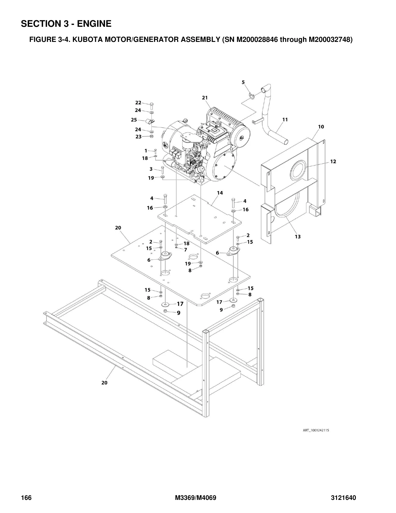
  • Section 3 – Engine: Kubota engine/generator installations and component breakdowns
  • Section 4 – Scissors Arms: Scissors arm installations and assemblies (with and without LSS), scissors arm guards
  • Section 5 – Platform: Platform installations (with and without D-rings and LSS), handrails, platform extension, console box assemblies, drive/steer controller
  • Section 6 – Cylinder: Axle lockout cylinder, leveling jack cylinder, lift cylinder assemblies, steer cylinder
  • Section 7 – Hydraulic: Hydraulic diagrams and schematics for 4WD, leveling jacks, lift cylinders, standard and oscillating axle configurations
  • Section 8 – Electrical: AC to platform installations, alarm and beacon harnesses, breaker box kits, charger cord plugs, front wheel assist harness, generator harness, ground control box harnesses, leveling jack harnesses, platform harnesses, receptacle box kits, valve harness
  • Section 9 – Decals: Decal installations for ANSI, Australian/CE, Brazil, Chinese, CSA, Japanese, Korean, Latin American specs and options
  • Section 10 – Recommended Service Parts Stock: Emergency repair parts list
  • Section 11 – Special Options: Airline to platform, arm guards, battery chargers, ClearSky telematics, decal kits, electrical connector kits, filter kits, fire extinguisher, fluids, ground control box illumination, platform padding, worklights, security lock, soft touch, spotlight, tie-strap, service tools
  • Part Number Index: Numerical listing of all part numbers with page references

IMAGES PREVIEW

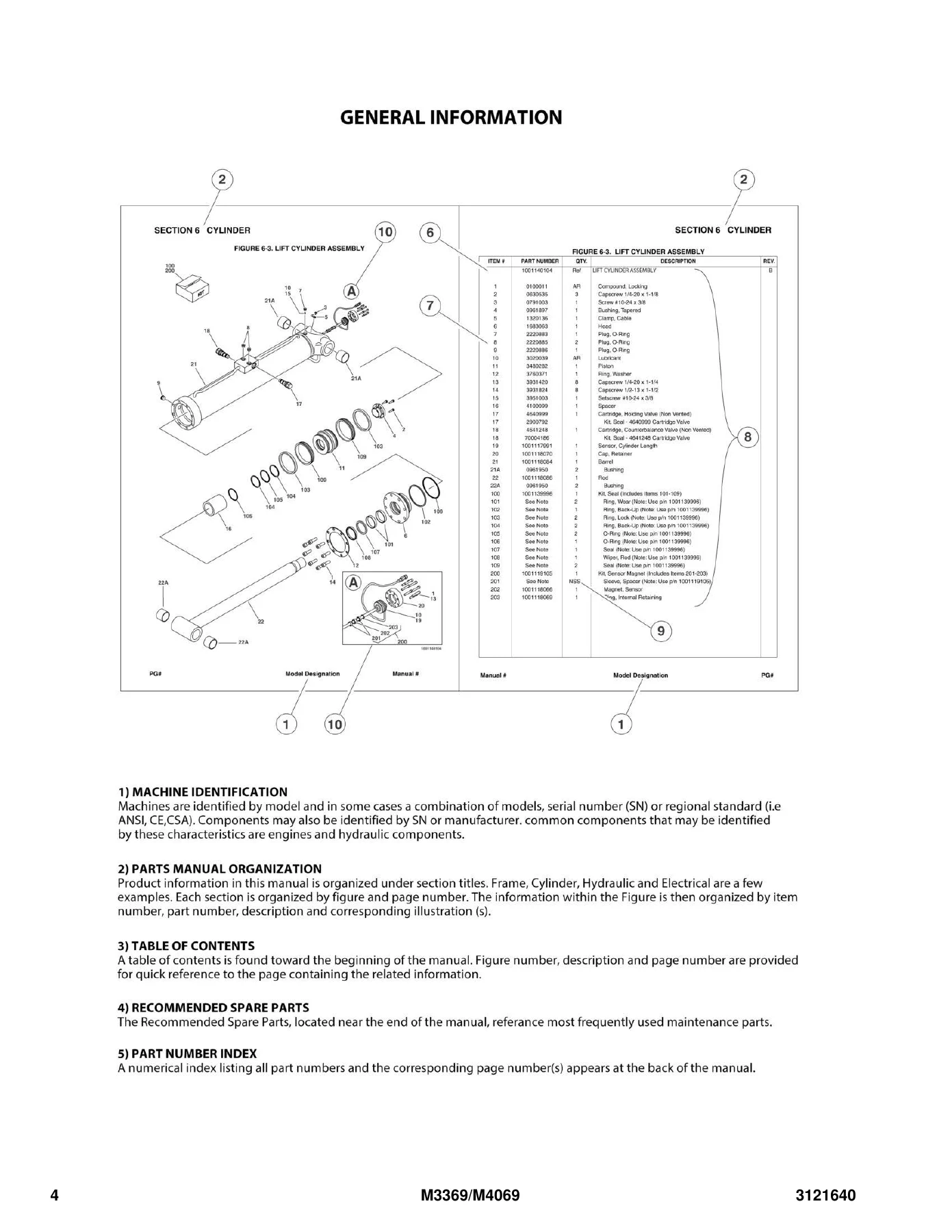
JLG 3369LE 4069LE M3369 M4069 Illustrated Parts Manual 3121640 Rev P — PDF page 4 preview
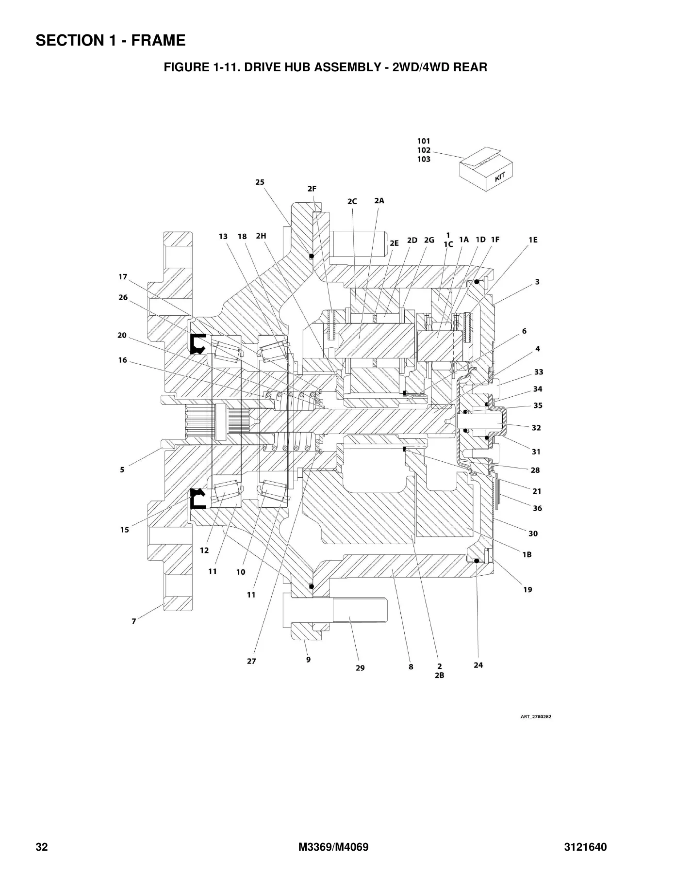
JLG 3369LE 4069LE M3369 M4069 Illustrated Parts Manual 3121640 Rev P — PDF page 32 preview
JLG 3369LE 4069LE M3369 M4069 Illustrated Parts Manual 3121640 Rev P — PDF page 166 preview

This JLG parts manual is organised so you can move from an illustration straight to the correct part number. Each figure shows a numbered exploded view of the assembly, and the facing parts list gives the item number, JLG part number, quantity, description and revision. The level of detail runs from complete assemblies down to individual O-rings, seals, bearings, bolts, washers and pins. Where a part has been superseded, the manual notes the replacement part number and the serial number range it applies to. Where a component is not sold separately, it is marked NSS or NLA so you know to purchase the complete assembly instead.

Serial number breaks are built into the listings throughout. Components for machines in the 0200230092 through 0200266243 range and the M200000100 through M200039307 range are called out separately where they differ, so you can match the right part to your exact machine.

Why This Manual Matters

Ordering the wrong part costs time and money. This JLG 3369LE 4069LE M3369 M4069 illustrated parts manual removes the guesswork by tying every part number to a picture and a position. Whether you are maintaining a single machine or running a fleet, having the correct exploded views and part numbers on hand means faster diagnosis, accurate ordering and fewer returns.

The manual covers the systems that matter most on these scissor lifts: the drive hubs and motors, the steering and axle assemblies, the hydraulic lift cylinders and control valves, the Kubota engine and generator package on the M-series, the ground and platform control boxes, the battery and charging systems, the leveling jacks, the scissors arms and the platform. Electrical harnesses are broken down to connector level, and hydraulic diagrams show the routing and fittings for each configuration.

Complete PDF Bookmark Tree

Complete Bookmarks

The complete bookmarks in the “JLG 3369LE 4069LE M3369 M4069 Illustrated Parts Manual 3121640 Rev P” are as follows:

SECTION 1 – FRAMEp. 11
FIGURE 1-1. REAR AXLE INSTALLATION – FIXEDp. 12
FIGURE 1-2. REAR AXLE INSTALLATION – OSCILLATING (ALL SPECS EXCEPT CE SPEC)p. 14
FIGURE 1-3. OSCILLATING AXLE VALVE ASSEMBLY (ALL SPECS EXCEPT CE SPEC)p. 16
FIGURE 1-4. REAR AXLE INSTALLATION – OSCILLATING (CE SPEC) (SN 0200246353 through 0200266243, SN M200000100 through M200039307)p. 18
FIGURE 1-5. OSCILLATING AXLE VALVE ASSEMBLY (CE SPEC) (SN 0200246353 through 0200266243, SN M200000100 through M200039307)p. 20
FIGURE 1-6. STEERING INSTALLATION – 2WDp. 22
FIGURE 1-7. STEERING INSTALLATION – 4WDp. 24
FIGURE 1-8. STEERING AND FRONT DRIVE INSTALLATION – 4WD FRONTp. 26
FIGURE 1-9. WHEEL DRIVE AND CONTROLLER INSTALLATION – 2WD/4WD REARp. 28
FIGURE 1-10. HUB ASSEMBLY – 2WD FRONTp. 30
FIGURE 1-11. DRIVE HUB ASSEMBLY – 2WD/4WD REARp. 32
FIGURE 1-12. DRIVE BRAKE ASSEMBLY – 2WD/4WD REARp. 36
FIGURE 1-13. DRIVE MOTOR ASSEMBLY – OPERATORS POSITION RH SIDE – 4WD FRONT (SN 0200230092 through 0200266243, SN M200000100 through M200023101)p. 38
FIGURE 1-14. DRIVE MOTOR ASSEMBLY – OPERATORS POSITION RH SIDE – 4WD FRONT (SN M200023102 through M200039307)p. 40
FIGURE 1-15. DRIVE MOTOR ASSEMBLY – OPERATORS POSITION LH SIDE – 4WD FRONT (SN 0200230092 through 0200266243, SN M200000100 through M200023101)p. 42
FIGURE 1-16. DRIVE MOTOR ASSEMBLY – OPERATORS POSITION LH SIDE – 4WD FRONT (SN M200023102 through M200039307)p. 44
FIGURE 1-17. DRIVE MOTOR ASSEMBLY – 2WD/4WD REARp. 46
FIGURE 1-18. DRIVE VALVE ASSEMBLY – 4WD ONLYp. 48
FIGURE 1-19. FLOW DIVIDER VALVE ASSEMBLY – 4WD ONLYp. 50
FIGURE 1-20. TIRE AND WHEEL INSTALLATION – IN240/55 X 17.5 FOAM-FILLEDp. 52
FIGURE 1-21. TIRE AND WHEEL INSTALLATION – IN240/55 X 17.5 NON-MARKING FOAM FILLEDp. 54
FIGURE 1-22. TIRE AND WHEEL INSTALLATION – 27.2/10.5LL X 15 TURF FOAM-FILLEDp. 56
FIGURE 1-23. LEVELING JACKS INSTALLATION – OPTIONALp. 58
FIGURE 1-24. LEVELING JACK CONTROL VALVE ASSEMBLYp. 60
FIGURE 1-25. BATTERY CHARGER INSTALLATION – 110V/60HZ (3369LE & 4069LE ANSI, ANSI EXPORT, CSA AND JAPANESE SPECS)p. 62
FIGURE 1-26. BATTERY CHARGER INSTALLATION – 110V/60HZ (M3369 & M4069 ANSI, ANSI EXPORT, CSA AND JAPANESE SPECS)p. 64
FIGURE 1-27. BATTERY CHARGER INSTALLATION – 120-240V/50-60HZ (3369LE & 4069LE ANSI, ANSI EXPORT, CSA AND CE SPECS)p. 66
FIGURE 1-28. BATTERY CHARGER INSTALLATION – 120-240V/50-60HZ (M3369 & M4069 ANSI, ANSI EXPORT, CSA AND CE SPECS)p. 68
FIGURE 1-29. BATTERY CHARGER INSTALLATION – 250V/50HZ (3369LE & 4069LE ANSI EXPORT AND AUSTRALIAN SPECS)p. 70
FIGURE 1-30. BATTERY CHARGER INSTALLATION – 250V/50HZ (M3369 & M4069 ANSI EXPORT AND AUSTRALIAN SPECS)p. 72
FIGURE 1-31. BATTERY CHARGER ASSEMBLYp. 74
FIGURE 1-32. BATTERY CHARGER DOOR ASSEMBLY – 3369LE & 4069LEp. 76
FIGURE 1-33. INVERTER INSTALLATION – OPTIONALp. 78
FIGURE 1-34. BEACON INSTALLATIONp. 80
FIGURE 1-35. LADDER INSTALLATION WITHOUT LEVELING JACKS – 3369LE/M3369 (ALL SPEC EXCEPT CE SPEC)p. 82
FIGURE 1-36. LADDER INSTALLATION WITHOUT LEVELING JACKS – 3369LE/M3369 (CE SPEC)p. 84
FIGURE 1-37. LADDER INSTALLATION WITHOUT LEVELING JACKS – 4069LE/M4069 (ALL SPECS EXCEPT CE SPEC)p. 86
FIGURE 1-38. LADDER INSTALLATION WITHOUT LEVELING JACKS – 4069LE/M4069 (CE SPECS)p. 88
FIGURE 1-39. LADDER INSTALLATION WITH LEVELING JACKSp. 90
FIGURE 1-40. FRAME COVER INSTALLATION (STANDARD)p. 92
FIGURE 1-41. FRAME COVER INSTALLATION (4069LE/M4069) (HOSTILE ENVIRONMENT)p. 94
FIGURE 1-42. FRAME COVER INSTALLATION (3369LE/M3369) (HOSTILE ENVIRONMENT)p. 96
SECTION 2 – GROUND COMPONENTSp. 99
FIGURE 2-1. MAIN CONTROL VALVE INSTALLATIONp. 100
FIGURE 2-2. MAIN CONTROL VALVE ASSEMBLYp. 102
FIGURE 2-3. HYDRAULIC COMPARTMENT INSTALLATIONp. 104
FIGURE 2-4. MOTOR ASSEMBLYp. 106
FIGURE 2-5. GROUND CONTROL BOX AND HORN INSTALLATIONS – 3369LE/4069LE WITHOUT LEVELING JACKS (ALL SPECS EXCEPT CE SPEC)p. 108
FIGURE 2-6. GROUND CONTROL BOX AND HORN INSTALLATIONS – 3369LE/4069LE WITHOUT LEVELING JACKS (CE SPEC)p. 110
FIGURE 2-7. GROUND CONTROL BOX AND HORN INSTALLATIONS – 3369LE/4069LE WITH LEVELING JACKS (ALL SPECS EXCEPT CE SPEC)p. 112
FIGURE 2-8. GROUND CONTROL BOX AND HORN INSTALLATIONS – 3369LE/4069LE WITH LEVELING JACKS (CE SPEC)p. 114
FIGURE 2-9. GROUND CONTROL BOX AND HORN INSTALLATIONS – M3369/M4069 (2WD – ALL SPECS EXCEPT CE SPEC)p. 116
FIGURE 2-10. GROUND CONTROL BOX AND HORN INSTALLATIONS – M3369/M4069 (2WD – CE SPEC)p. 118
FIGURE 2-11. GROUND CONTROL BOX AND HORN INSTALLATIONS – M3369/M4069 (4WD – ALL SPECS EXCEPT CE SPEC)p. 120
FIGURE 2-12. GROUND CONTROL BOX AND HORN INSTALLATIONS – M3369/M4069 (4WD – CE SPEC)p. 122
FIGURE 2-13. GROUND CONTROL BOX AND HORN INSTALLATIONS – M4069 (DRIVE AT FULL HEIGHT)p. 124
FIGURE 2-14. GROUND CONTROL BOX ASSEMBLY – 3369LE/4069LE (ALL SPECS EXCEPT CE SPEC)p. 126
FIGURE 2-15. GROUND CONTROL BOX ASSEMBLY – 3369LE/4069LE (CE SPEC)p. 128
FIGURE 2-16. GROUND CONTROL BOX ASSEMBLY – M3369/M4069 (ALL SPECS EXCEPT CE SPEC)p. 130
FIGURE 2-17. GROUND CONTROL BOX ASSEMBLY – M3369/M4069 (CE SPECS)p. 132
FIGURE 2-18. GROUND CONTROL BOX ASSEMBLY – M4069 DRIVE AT FULL HEIGHTp. 134
FIGURE 2-19. GROUND CONTROL BOX COMPONENTS (SN 0200243015 through 0200266243, SN M200000100 through M200039307)p. 136
FIGURE 2-20. BATTERY BOX INSTALLATION – 370A-H BATTERIES (SN 0200230092 through 0200258591)p. 138
FIGURE 2-21. BATTERY BOX INSTALLATION – 370A-H BATTERIES (SN 0200258591 through 0200266243)p. 140
FIGURE 2-22. BATTERY BOX INSTALLATION – 390A-H AGM BATTERIES (SN 0200230092 through 0200258591)p. 142
FIGURE 2-23. BATTERY BOX INSTALLATION – 390A-H AGM BATTERIES (SN 0200258591 through 0200266243, SN M200009860 through M200039307)p. 144
FIGURE 2-24. ALARM INSTALLATIONp. 146
FIGURE 2-25. ALARM INSTALLATION – MOTIONp. 148
FIGURE 2-26. COVERS INSTALLATIONp. 150
FIGURE 2-27. TANK INSTALLATION – M3369/M4069 (MACHINES WITH STANDARD BATTERY)p. 154
FIGURE 2-28. TANK INSTALLATION – M3369/M4069 (MACHINES WITH AGM BATTERY)p. 156
SECTION 3 – ENGINEp. 159
FIGURE 3-1. KUBOTA ENGINE/GENERATOR INSTALLATION – M3369/M4069 (WITH STANDARD BATTERY)p. 160
FIGURE 3-2. KUBOTA ENGINE/GENERATOR INSTALLATION – M3369/M4069 (WITH AGM BATTERY)p. 162
FIGURE 3-3. KUBOTA MOTOR/GENERATOR ASSEMBLY (SN 0200230092 through 0200266243, SN M200000100 through M200028845)p. 164
FIGURE 3-4. KUBOTA MOTOR/GENERATOR ASSEMBLY (SN M200028846 through M200032748)p. 166
FIGURE 3-5. KUBOTA MOTOR/GENERATOR ASSEMBLY (SN M200032749 through M200039307)p. 168
FIGURE 3-6. KUBOTA MOTOR/GENERATOR COMPONENTS (SN 0200230092 through 0200266243, SN M200000100 through M200028845)p. 170
FIGURE 3-7. KUBOTA MOTOR/GENERATOR COMPONENTS (SN M200028846 through M200032748)p. 174
FIGURE 3-8. KUBOTA MOTOR/GENERATOR COMPONENTS (SN M200032749 through M200039307)p. 178
SECTION 4 – SCISSORS ARMSp. 181
FIGURE 4-1. SCISSORS ARMS INSTALLATION WITHOUT LSS – 3369LE/M3369p. 182
FIGURE 4-2. SCISSORS ARMS ASSEMBLY WITHOUT LSS – 3369LE/M3369p. 184
FIGURE 4-3. SCISSORS ARMS INSTALLATION WITH LSS – 3369LE/M3369p. 188
FIGURE 4-4. SCISSORS ARMS ASSEMBLY WITH LSS – 3369LE/M3369p. 190
FIGURE 4-5. SCISSORS ARMS INSTALLATION WITHOUT LSS – 4069LE/M4069p. 194
FIGURE 4-6. SCISSORS ARMS ASSEMBLY WITHOUT LSS – 4069LE/M4069p. 196
FIGURE 4-7. SCISSORS ARMS INSTALLATION WITH LSS – 4069LE/M4069p. 200
FIGURE 4-8. SCISSORS ARMS ASSEMBLY WITH LSS – 4069LE/M4069p. 202
FIGURE 4-9. SCISSORS ARM GUARDS INSTALLATION (CE SPECS ONLY)p. 206
SECTION 5 – PLATFORMp. 209
FIGURE 5-1. PLATFORM INSTALLATION WITHOUT D-RINGSp. 210
FIGURE 5-2. PLATFORM INSTALLATION WITH D-RINGSp. 212
FIGURE 5-3. PLATFORM INSTALLATION WITHOUT D-RINGS AND WITH LSSp. 214
FIGURE 5-4. PLATFORM INSTALLATION WITH D-RINGS AND WITH LSSp. 218
FIGURE 5-5. HANDRAILS INSTALLATION WITH SELF-CLOSING GATEp. 222
FIGURE 5-6. HANDRAILS INSTALLATION WITH CHAIN GATEp. 224
FIGURE 5-7. 3FT PLATFORM EXTENSION W/RAILSp. 226
FIGURE 5-8. CONSOLE BOX ASSEMBLY – 3369LE/4069LE NO LEVELINGp. 228
FIGURE 5-9. CONSOLE BOX ASSEMBLY – 3369LE/4069LE WITH LEVELING JACKSp. 230
FIGURE 5-10. CONSOLE BOX ASSEMBLY – M3369/M4069 2WD NO LEVELING JACKSp. 232
FIGURE 5-11. CONSOLE BOX ASSEMBLY – M3369/M4069 2WD WITH LEVELING JACKSp. 234
FIGURE 5-12. CONSOLE BOX ASSEMBLY – M3369/M4069 4WD NO LEVELING JACKSp. 236
FIGURE 5-13. CONSOLE BOX ASSEMBLY – M3369/M4069 4WD WITH LEVELING JACKSp. 238
FIGURE 5-14. DRIVE/STEER CONTROLLER ASSEMBLYp. 240
SECTION 6 – CYLINDERp. 243
FIGURE 6-1. AXLE LOCKOUT CYLINDER ASSEMBLYp. 244
FIGURE 6-2. LEVELING JACK CYLINDER ASSEMBLYp. 246
FIGURE 6-3. LIFT CYLINDER ASSEMBLY – 3369LE/M3369p. 248
FIGURE 6-4. LIFT (LOWER) CYLINDER ASSEMBLY – 4069LE/M4069p. 250
FIGURE 6-5. LIFT (UPPER) CYLINDER ASSEMBLY – 4069LE/M4069p. 252
FIGURE 6-6. STEER CYLINDER ASSEMBLYp. 254
SECTION 7 – HYDRAULICp. 257
FIGURE 7-1. HYDRAULIC DIAGRAM LISTp. 258
FIGURE 7-2. HYDRAULIC DIAGRAM – 4WDp. 260
FIGURE 7-3. HYDRAULIC DIAGRAM – LEVELING JACKS (OPTIONAL)p. 262
FIGURE 7-4. HYDRAULIC DIAGRAM – LIFT CYLINDER – 3369LE/M3369 WITHOUT LSSp. 264
FIGURE 7-5. HYDRAULIC DIAGRAM – LIFT CYLINDER – 3369LE/M3369 WITH LSSp. 266
FIGURE 7-6. HYDRAULIC DIAGRAM – LIFT CYLINDER – 4069LE/M4069 WITHOUT LSSp. 268
FIGURE 7-7. HYDRAULIC DIAGRAM – LIFT CYLINDER – 4069LE/M4069 WITH LSSp. 270
FIGURE 7-8. HYDRAULIC DIAGRAM – STANDARD – 3369LE/M3369 WITH FIXED AXLEp. 272
FIGURE 7-9. HYDRAULIC DIAGRAM – STANDARD – 3369LE/M3369 WITH OSCILLATING AXLE (ALL SPECS EXCEPT CE SPEC)p. 274
FIGURE 7-10. HYDRAULIC DIAGRAM – STANDARD – 4069LE/M4069 WITH FIXED AXLEp. 278
FIGURE 7-11. HYDRAULIC DIAGRAM – STANDARD – 4069LE/M4069 WITH OSCILLATING AXLE (ALL SPECS EXCEPT CE SPEC)p. 280
FIGURE 7-12. HYDRAULIC DIAGRAM – STANDARD – 3369LE/M3369 WITH OSCILLATING AXLE (CE SPEC) (SN 0200246353 through 0200266243, SN M200000100 through M200039307)p. 284
FIGURE 7-13. HYDRAULIC DIAGRAM – STANDARD – 4069LE/M4069 WITH OSCILLATING AXLE (CE SPEC) (SN 0200246353 through 0200266243, SN M200000100 through M200039307)p. 288
SECTION 8 – ELECTRICALp. 293
FIGURE 8-1. ELECTRICAL DIAGRAM LISTp. 294
FIGURE 8-2. AC TO PLATFORM INSTALLATION – 110V GFI (3369LE/M3369)p. 296
FIGURE 8-3. AC TO PLATFORM INSTALLATION – 110V GFI (4069LE/M4069)p. 298
FIGURE 8-4. AC TO PLATFORM INSTALLATION – 110V IEC YELLOW (CE SPEC ONLY)p. 300
FIGURE 8-5. AC TO PLATFORM INSTALLATION – 220V IEC BLUE (CE SPEC ONLY)p. 302
FIGURE 8-6. AC TO PLATFORM INSTALLATION – 220V AFSINT107 (CE SPEC ONLY)p. 304
FIGURE 8-7. AC TO PLATFORM INSTALLATION – 220V CEE7 SIDE GROUND (CE SPEC ONLY)p. 306
FIGURE 8-8. AC TO PLATFORM INSTALLATION – 220V CEE7 POST GROUND (CE SPEC ONLY)p. 308
FIGURE 8-9. ALARM HARNESSp. 310
FIGURE 8-10. BEACON LIGHT HARNESSp. 312
FIGURE 8-11. BREAKER BOX KIT WITH TWO BREAKERS – CE SPEC ONLYp. 314
FIGURE 8-12. BREAKER BOX KIT WITH THREE BREAKERS – CE SPEC ONLYp. 316
FIGURE 8-13. CHARGER CORD PLUG INSTALLATION – 110V IEC YELLOW PLUG (CE SPEC)p. 318
FIGURE 8-14. CHARGER CORD PLUG INSTALLATION – 220V IEC BLUE PLUG (CE SPEC)p. 320
FIGURE 8-15. CHARGER CORD PLUG INSTALLATION – 220V AFSINT 107 KEYED GROUND (CE SPEC)p. 322
FIGURE 8-16. CHARGER CORD PLUG INSTALLATION – 220V CEE7 POST GROUND (CE SPEC)p. 324
FIGURE 8-17. CHARGER CORD PLUG INSTALLATION – 220V CEE7 SIDE GROUND (CE SPEC)p. 326
FIGURE 8-18. FRONT WHEEL ASSIST (4WD) HARNESSp. 328
FIGURE 8-19. GENERATOR HARNESS – M3369/M4069 ONLYp. 330
FIGURE 8-20. GROUND CONTROL BOX HARNESS – 3369LE/4069LEp. 332
FIGURE 8-21. GROUND CONTROL BOX HARNESS – M3369/M4069p. 334
FIGURE 8-22. GROUND CONTROL BOX HARNESS (M4069 DRIVE AT FULL HEIGHT)p. 336
FIGURE 8-23. GROUND CONTROL BOX TO BULKHEAD HARNESS INSTALLATION – 3369LE/M3369p. 338
FIGURE 8-24. GROUND CONTROL BOX TO BULKHEAD HARNESS INSTALLATION – 4069LE/M4069p. 340
FIGURE 8-25. GROUND CONTROL BOX TO BULKHEAD HARNESSp. 342
FIGURE 8-26. LEVELING JACK HARNESSp. 344
FIGURE 8-27. LEVELING JACK N.C. HARNESSp. 346
FIGURE 8-28. LEVELING JACK N.O. HARNESSp. 348
FIGURE 8-29. LEVELING JACK VALVE HARNESSp. 350
FIGURE 8-30. LIFT DOWN HARNESS – LOWERp. 352
FIGURE 8-31. LIFT DOWN HARNESS – 3369LE/M3369 UPPERp. 354
FIGURE 8-32. LIFT DOWN HARNESS – 4069LE/M4069 UPPERp. 356
FIGURE 8-33. PLATFORM CABLE HARNESS – 3369LE/M3369p. 358
FIGURE 8-34. PLATFORM CABLE HARNESS – 4069LE/M4069p. 360
FIGURE 8-35. PLATFORM CONSOLE BOX HARNESS WITHOUT LEVELING JACKSp. 362
FIGURE 8-36. PLATFORM CONSOLE BOX HARNESS WITH LEVELING JACKSp. 364
FIGURE 8-37. RECEPTACLE BOX KIT – 110V GFIp. 366
FIGURE 8-38. RECEPTACLE BOX KIT – 110V IEC YELLOW (CE SPEC)p. 368
FIGURE 8-39. RECEPTACLE BOX KIT – 220V IEC BLUE (CE SPEC)p. 370
FIGURE 8-40. RECEPTACLE BOX KIT – 220V AFSINT 107 (CE SPEC)p. 372
FIGURE 8-41. RECEPTACLE BOX KIT – 220V CEE7 SIDE GROUND (CE SPEC)p. 374
FIGURE 8-42. RECEPTACLE BOX KIT – 220V CEE7 POST GROUND (CE SPEC)p. 376
FIGURE 8-43. VALVE HARNESSp. 378
SECTION 9 – DECALSp. 381
FIGURE 9-1. DECAL INSTALLATION – ANSI SPEC (ENGLISH)p. 382
FIGURE 9-2. DECAL INSTALLATION – AUSTRALIAN AND CE SPECS – 3369LE & 4069LEp. 384
FIGURE 9-3. DECAL INSTALLATION – AUSTRALIAN AND CE SPECS – M3369 & M4069p. 386
FIGURE 9-4. DECAL INSTALLATION – BRAZIL SPEC (DUAL LANGUAGE – PORTUGUESE/SPANISH)p. 388
FIGURE 9-5. DECAL INSTALLATION – CHINESE SPEC (DUAL LANGUAGE – ENGLISH/CHINESE)p. 390
FIGURE 9-6. DECAL INSTALLATION – CSA SPEC (DUAL LANGUAGE – ENGLISH/FRENCH)p. 392
FIGURE 9-7. DECAL INSTALLATION – JAPANESE SPEC (DUAL LANGUAGE – ENGLISH/JAPANESE)p. 394
FIGURE 9-8. DECAL INSTALLATION – KOREAN SPEC (DUAL LANGUAGE – ENGLISH/KOREAN)p. 396
FIGURE 9-9. DECAL INSTALLATION – LATIN AMERICAN SPEC (DUAL LANGUAGE – ENGLISH/SPANISH)p. 398
FIGURE 9-10. DECAL INSTALLATION – OPTIONSp. 400
SECTION 10 – RECOMMENDED SERVICE PARTS STOCKp. 403
FIGURE 10-1. RECOMMENDED SERVICE PARTS STOCKp. 404
SECTION 11 – SPECIAL OPTIONSp. 405
FIGURE 11-1. SPECIAL OPTIONSp. 406
PART NUMBER INDEXp. 409

Because this is a parts manual rather than a service manual, it does not walk you through repair procedures – but it gives you the complete parts identification system that a service manual assumes you already have. Used alongside the machine’s service documentation, it lets you order seals, bearings, valves, coils, switches, cables, hoses, fittings, decals and structural components with confidence.

Who This Is For

This PDF is for JLG owners, fleet managers, workshop technicians and parts departments working on 3369LE, 4069LE, M3369 and M4069 scissor lifts. If you need to identify a part from a drawing, cross-reference a superseded number, or build a stock list for these machines, the 3121640 Rev P manual is the reference you want.

Instant PDF Delivery

You get the complete JLG 3369LE 4069LE M3369 M4069 Illustrated Parts Manual 3121640 Rev P as a PDF download immediately after purchase. No shipping, no waiting. View it on any device – laptop, tablet or phone – and print the pages you need for the workshop. The full document stays with you for as long as you need it.
Reviews

There are no reviews yet.

Be the first to review “JLG 3369LE 4069LE M3369 M4069 Illustrated Parts Manual 3121640 Rev P”

What Our Customers Say

★★★★★ Live reviews from customers
Loading customer reviews...
0
    0
    Your Cart
    Your cart is emptyReturn to Shop
    🛒
    Recently Purchased
    🕒 verified order