
JLG 400S & 460SJ Illustrated Parts Manual 3120789 – 2015 PDF
Original price was: $34.95.$20.95Current price is: $20.95.
338-page illustrated parts manual for JLG 400S and 460SJ boom lifts. Covers all major systems with exploded-view illustrations, part numbers, serial number breaks, and hydraulic/electrical diagrams for Caterpillar, Deutz, Ford, GM, and Isuzu engine configurations.
Description
JLG 400S & 460SJ Illustrated Parts Manual 3120789 – 2015 PDF
This JLG 400S & 460SJ Illustrated Parts Manual is the complete parts reference for these articulating boom lift models, covering every major system with exploded-view illustrations and detailed parts lists. With 338 pages, this manual gives technicians, fleet managers, and owners the exact part numbers, descriptions, and quantities needed to identify and order components correctly. Whether you’re performing routine maintenance or tackling a major repair, this illustrated parts manual for the JLG 400S and 460SJ provides the visual guidance and parts data you need.
File Details
- Manual Type: Illustrated Parts Manual
- Brand: JLG
- Models Covered: 400S, 460SJ
- Document Number: 3120789
- Date: 2015 (Revised November 20, 2015)
- Language: English
- Page Count: 338
- File Format: PDF
Chapters Covered
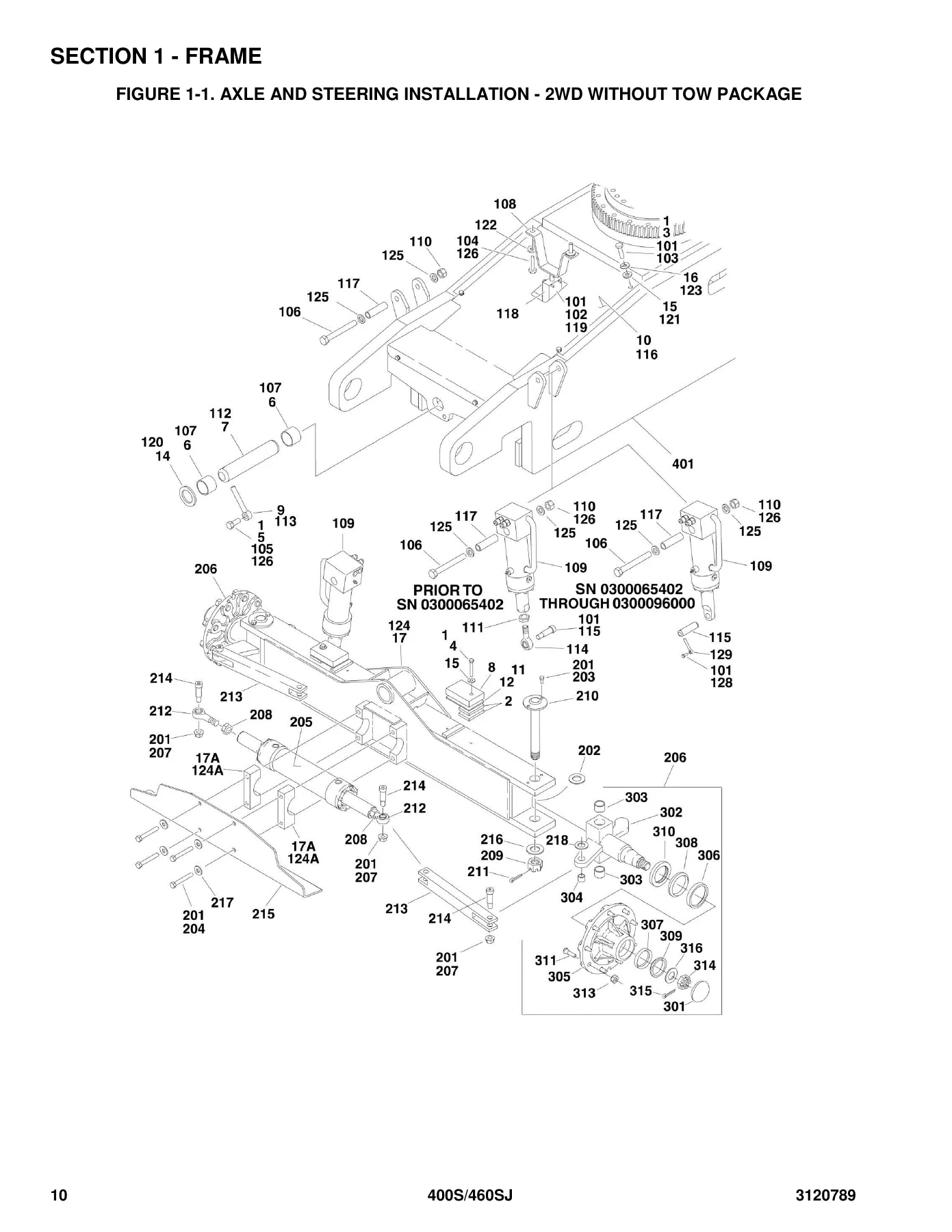
- Section 1 – Frame: Axle and Steering Installations (2WD Without Tow Package, 2WD With Tow Package, 4WD), Tire and Wheel Drive Installations, Drive Hub Assembly (4WD Front), Drive Hub/Brake Assembly (Rear), Drive Hub and Hub with Brake Assemblies, Drive Motor Assembly (Original Equipment – 4 Bolt), Drive Motor Assembly (Field Service Replacement – 5 Bolt), Frame Valves and Shields Installation, Semi-Track Installation, Tow Package Installation
- Section 2 – Turntable: Valves and Tilt Indicator Installations, Main Control Valve Assembly, Articulating Jib Valve Assembly, Turntable and Swing Drive Installations, Swing Brake Assembly, Swing Hub Assembly, Swing Motor Assembly, Caterpillar Engine Installation, Generator Installation (Caterpillar), Deutz Engine Installation, Generator Installation (Deutz), Ford Engine Installation, Dual Fuel Installations, Generator Installation (Ford), GM Engine Installation, Generator Installation (GM), Isuzu Engine Installation – 4LE1, Generator Installation (Isuzu), Piston Pump Assembly, Gear Pump Assembly, Auxiliary Pump Assembly, Tank Installations, Ground Control Box Assembly (Without ADE System), Ground Control Box Assembly (With ADE System), Electrical Options Installation, Hoods Installation
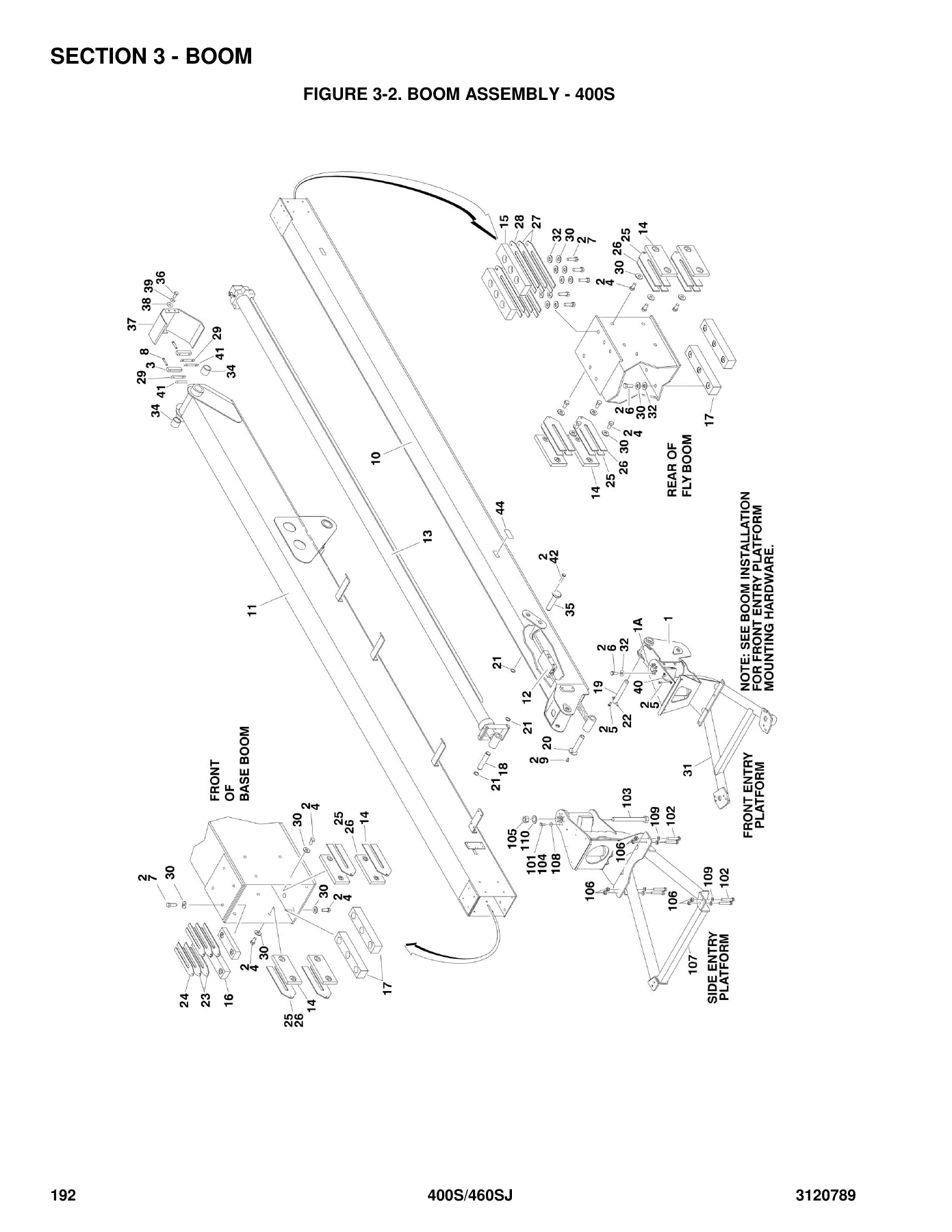
- Section 3 – Boom: Boom Installations, Boom Assembly – 400S, Boom Assembly – 460SJ, Rotator Assemblies
- Section 4 – Platform: Platform Installation (Front Entry Platform), Platform Installation (Side Entry Platform), Soft Touch Installation (Front Entry Platform), Soft Touch Installation (Side Entry Platform), Platform Console Assembly (Without ADE System), Platform Console Assembly (With ADE System), Controller Assembly (Swing and Lift), Controller Assembly (Drive and Steer)
- Section 5 – Cylinder: Axle Lockout Cylinder Assembly, Level (Platform Slave) Cylinder Assembly, Level (Platform Slave) Cylinder Assembly (400S Service Replacement), Lift Cylinder Assembly – Jib (460SJ), Lift Cylinder Assembly – Main, Master Cylinder Assembly (Original Equipment), Master Cylinder Assembly (Service Replacement), Steer Cylinder Assembly (Original Equipment), Steer Cylinder Assembly (Service Replacement and Original Equipment), Telescope Cylinder Assembly
- Section 6 – Hydraulic: Axle Lockout Hydraulic Diagram, Drive Hydraulic Diagram – 2WD, Drive Hydraulic Diagram – 4WD, Standard Hydraulic Diagram, Hydraulic Diagram List
- Section 7 – Electrical: Electrical Diagram List, Harness Components Installation (Without ADE System), Harness Components Installation (With ADE System)
- Section 8 – Decals: Decal Installation (ANSI Spec), Decal Installation (Country Spec)
- Section 9 – Recommended Service Parts Stock: Model 400S/460SJ Standard Parts, Model 400S/460SJ Variable Parts
- Section 10 – Special Options: Special Options List, SkyWelder Installation
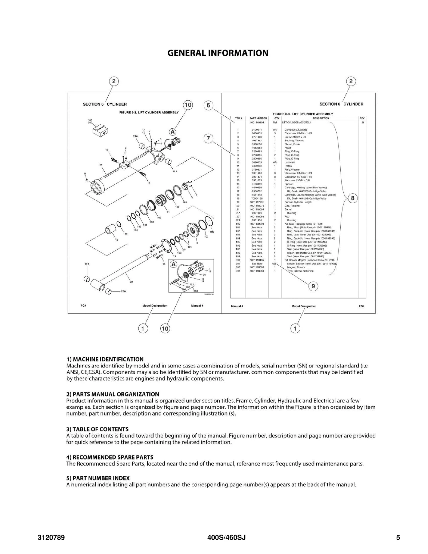
What makes this JLG 400S & 460SJ Illustrated Parts Manual particularly valuable is its organization by system and its attention to serial number breaks. Each figure is accompanied by a parts list that includes item numbers corresponding to callouts on the illustration, part numbers, quantities, and descriptions. The manual covers the full range of configurations, from 2WD to 4WD, from standard machines to those equipped with the ADE System, and from multiple engine platforms including Caterpillar, Deutz, Ford, GM, and Isuzu.
Serial Number Breaks and Model Variations
The JLG 400S and 460SJ machines were produced across a range of serial numbers, and this manual accounts for the parts changes that occurred throughout production. Serial number breaks are noted throughout the parts lists, with specific ranges indicated for components that changed over time. For example, the manual distinguishes between machines prior to SN 0300067471, SN 0300067471 through 0300072505, and SN 0300072506 through 0300096000 for various frame and axle components. Similar breakpoints exist for the ADE System introduction (SN 0300064404), drive hub assemblies (SN 0300076633), and many other components. Always compare your machine’s serial number against the ranges shown in the manual before ordering parts.
Engine and Powertrain Coverage
The JLG 400S & 460SJ Illustrated Parts Manual covers machines equipped with several engine options. The Caterpillar engine installation section includes detailed parts breakdowns for the engine assembly, cooling system, exhaust, air intake, and associated hardware. The Deutz engine installation covers the F3M2011 and F4M2011 engines, with separate sections for machines before and after SN 0300077682. The Ford engine installation covers the LRG-425 engine in both standard gas and dual fuel configurations, with coverage for Tier I and Tier II engines. The GM engine installation covers the 3.0L engine, and the Isuzu engine installation covers the 4LE1 diesel. Each engine section includes the pumps, generator (if equipped), and all mounting hardware.
Hydraulic and Electrical Systems
The hydraulic diagrams section provides complete schematics for the axle lockout system, 2WD drive system, 4WD drive system, and standard hydraulic system. These diagrams show hose routings, fitting part numbers, valve locations, and component connections. The electrical section includes harness component installations for machines both with and without the ADE System, showing connector part numbers, wire routing, and component locations. These diagrams are invaluable for troubleshooting and for identifying the correct hoses, fittings, and electrical components when replacements are needed.
Platform and Controller Assemblies
The platform section covers both front entry and side entry platforms, including the soft touch installation for each. The platform console assembly is detailed for machines both with and without the ADE System, with parts breakdowns for the console box, switches, relays, controllers, and associated hardware. The controller assemblies for swing/lift and drive/steer functions are shown in both original equipment and service replacement configurations, with detailed parts lists for each.
Cylinder Assemblies
Section 5 provides comprehensive parts breakdowns for every cylinder on the JLG 400S and 460SJ, including the axle lockout cylinder, level (platform slave) cylinder, jib lift cylinder (460SJ), main lift cylinder, master cylinder, steer cylinder, and telescope cylinder. Each cylinder assembly is shown in exploded view with part numbers for the barrel, rod, head, piston, seals, valves, and all internal components. Seal kits are listed separately where applicable, making it easy to order the correct seal kit for a rebuild.
Decals and Special Options
The decal section covers both ANSI spec and country spec decal installations, with part numbers for every safety and informational decal on the machine. The special options section covers the SkyWelder installation, with parts breakdowns for the welder assembly, mounting hardware, and electrical connections. Additional special options are listed with their part numbers for easy reference.
Recommended Service Parts Stock
Section 9 provides a list of recommended service parts to keep in stock for emergency repairs. This section is divided into standard parts (filters, relays, switches, controllers) and variable parts (engine-specific filters and components). This is a practical reference for fleet managers who want to minimize downtime by having commonly needed parts on hand.
Part Number Index
A comprehensive part number index at the back of the manual lists every part number in the book along with the page number(s) where it appears. This makes it easy to look up a specific part number and find all the information about it, including which assembly it belongs to and what other parts are used with it.
Get Instant Access to Your JLG 400S & 460SJ Parts Manual
This JLG 400S & 460SJ Illustrated Parts Manual is delivered as an instant PDF download, so you can start using it immediately after purchase. No shipping delays, no waiting for a physical book to arrive. The PDF format lets you search for part numbers, zoom in on illustrations, and print only the pages you need. Whether you’re a technician in the shop, a fleet manager in the office, or an owner-operator in the field, this manual gives you the parts information you need to keep your JLG boom lift running efficiently. With 338 pages of detailed illustrations and parts data, it’s an essential addition to your service library.

Reviews
There are no reviews yet.