JLG 400S 460SJ Service & Maintenance Manual (3120788) – PDF DOWNLOAD
TABLE OF CONTENTS:
JLG 400S 460SJ Service & Maintenance Manual (3120788) – PDF DOWNLOAD
Section A. INTRODUCTION - MAINTENANCE SAFETY PRECAUTIONS............................ 3
A General....................................................................... 3
B Hydraulic System Safety....................................................... 3
C Maintenance................................................................... 3
Section 1. SPECIFICATIONS....................................................... 21
1.1 Capacities.............................................................. 21
1.2 Engine Specifications................................................... 21
1.3 Tires................................................................... 22
1.4 Specifications and Performance Data..................................... 23
1.5 Torque Requirements..................................................... 24
1.6 Critical Stability Weights.............................................. 24
1.7 Major Component Weights................................................. 24
1.8 Function Speeds......................................................... 25
1.9 Pressure Settings - PSI (Bar)........................................... 25
1.10 Cylinder Specifications................................................ 25
1.11 Lubrication............................................................ 25
Hydraulic Oil........................................................... 25
1.12 Welder, Hydraulic (option)............................................. 26
1.13 Serial Number Location................................................. 26
1.14 Operator Maintenance and Lubrication................................... 27
Draining Oil Build Up From The Propane Regulator........................ 30
Propane Fuel Filter Replacement......................................... 31
Propane Fuel System Pressure Relief..................................... 32
Section 2. GENERAL.............................................................. 41
2.1 Machine Preparation, Inspection, and Maintenance........................ 41
General................................................................. 41
Preparation, Inspection, and Maintenance................................ 41
Pre-Start Inspection.................................................... 41
Pre-Delivery Inspection and Frequent Inspection......................... 41
Annual Machine Inspection............................................... 41
Preventative Maintenance................................................ 41
2.2 Service and Guidelines.................................................. 42
General................................................................. 42
Safety and Workmanship.................................................. 42
Cleanliness............................................................. 42
Components Removal and Installation..................................... 42
Component Disassembly and Reassembly.................................... 43
Pressure-Fit Parts...................................................... 43
Bearings................................................................ 43
Gaskets................................................................. 43
Bolt Usage and Torque Application....................................... 43
Hydraulic Lines and Electrical Wiring................................... 43
Hydraulic System........................................................ 43
Lubrication............................................................. 43
Battery................................................................. 43
Lubrication and Servicing............................................... 43
2.3 Lubrication and Information............................................. 43
Hydraulic System........................................................ 43
Hydraulic Oil........................................................... 44
Changing Hydraulic Oil.................................................. 44
Lubrication Specifications.............................................. 44
2.4 Cylinder Drift Test..................................................... 44
Platform Drift.......................................................... 44
Cylinder Drift.......................................................... 44
2.5 Pins and Composite Bearing Repair Guidelines............................ 45
2.6 Welding on JLG Equipment................................................ 45
Do the Following When Welding on JLG Equipment.......................... 45
Do NOT Do the Following When Welding on JLG Equipment................... 45
Section 3. CHASSIS & TURNTABLE.................................................. 55
3.1 Tires & Wheels.......................................................... 55
Tire Inflation.......................................................... 55
Tire Damage............................................................. 55
Tire Replacement........................................................ 55
Wheel Replacement....................................................... 55
Wheel Installation...................................................... 55
3.2 Drive Hub Part No. 2780243 (2wd Rear) Part No. 2780244 (4wd Rear)....... 56
Disassembly............................................................. 56
Disassembly of Cover Unit (8)........................................... 57
Disassembly of First Stage Planetary Assembly........................... 57
Disassembly of the Second Stage Planet Gears (1)........................ 57
Assembly of First Stage Planetary Assembly (7).......................... 57
Assembly Of End Cover Unit (8).......................................... 57
Final Assembly.......................................................... 57
3.3 Drive Hub Part No. 2780246 (4wd steer axle Prior to S/N 0300076633)..... 59
Disassembly............................................................. 59
Disassembly of Cover Unit (8)........................................... 59
Disassembly of First Stage Planetary Assembly........................... 59
Disassembly of the Second Stage Planet Gears (1)........................ 59
Assembly of First Stage Planetary Assembly (7).......................... 60
Assembly of End Cover Unit (8).......................................... 60
Final Assembly.......................................................... 60
3.4 Torque Hub - 4WD (Machines built after S/N 0300076633).................. 62
Roll and Leak Testing................................................... 62
Tightening and Torquing Bolts........................................... 62
Oil Information......................................................... 62
Main Disassembly for ”B” Drives......................................... 62
Hub-Spindle Disassembly................................................. 63
Cover Disassembly....................................................... 63
Carrier Disassembly..................................................... 63
Assembly of the Carrier................................................. 64
Cover Sub-Assembly...................................................... 66
Hub-Spindle Sub-Assembly................................................ 67
Main Assembly........................................................... 69
Tool List............................................................... 74
3.5 Re-Aligning Torque Hub Input Coupling................................... 75
Equipment Required...................................................... 75
Procedure............................................................... 75
3.6 Drive Brake............................................................. 76
Pre-Installation Checks................................................. 76
Installation............................................................ 77
Maintenance............................................................. 77
Disassembly............................................................. 77
Examination............................................................. 77
Assembly................................................................ 77
3.7 Drive Motor............................................................. 79
Description............................................................. 79
Shaft Seal Replacement.................................................. 79
Loop Flushing Valve..................................................... 80
Troubleshooting......................................................... 81
Disassembly............................................................. 82
Inspection.............................................................. 86
Assembly................................................................ 88
Initial Start-up Procedures............................................. 93
3.8 Adjustment Procedure For Lockout Valve.................................. 94
3.9 Toe-In Adjustment....................................................... 94
3.10 2WD Hub................................................................ 95
Removal & Disassembly................................................... 95
Cleaning & Inspection................................................... 95
Assembly & Installation................................................. 96
3.11 Oscillating Axle Bleeding Procedure.................................... 97
3.12 Oscillating Axle Lockout Test.......................................... 97
3.13 Swing Bearing.......................................................... 98
Turntable Bearing Mounting Bolt Condition Check......................... 98
Wear Tolerance.......................................................... 99
Replacement of Swing Bearing............................................100
Swing Bearing Torque Value..............................................101
Swing Drive Installation................................................101
3.14 Swing Brake (Prior to S/N 64802).......................................104
Installation............................................................104
Brake Disassembly.......................................................104
Assembly Information....................................................104
3.15 Swing Brake S/N 64802 to Present.......................................106
Disassembly.............................................................106
Assembly................................................................106
3.16 Swing Drive Torque Hub.................................................108
Disassembly Procedure...................................................108
Hub Shaft Sub-Assembly Procedure........................................112
Carrier Sub-Assembly Procedure..........................................114
3.17 Semi-Track.............................................................115
Testing the Track.......................................................115
Removing the Track......................................................116
Assuming Normal Wear....................................................116
Adjustment..............................................................116
3.18 Generator..............................................................120
Every 250 hours.........................................................120
Every 500 hours.........................................................120
Overload Protection.....................................................120
Inspecting Brushes, Replacing Brushes, and Cleaning Slip Rings..........120
3.19 Ford EFI Engine........................................................122
Performing Diagnostics..................................................122
Visual/Physical Engine Inspection Check.................................122
EFI Diagnostics (Prior to S/N 61718)....................................122
ECM AND SENSORS.........................................................123
Fuel System.............................................................129
3.20 Throttle Checks and Adjustments - Deutz Engine (Prior to S/N 61718)....133
General.................................................................133
Procedure...............................................................134
Controller Status.......................................................134
Failure Modes...........................................................134
3.21 Tilt Alarm Switch (Prior to S/N 61718).................................137
Manual Adjustment.......................................................137
3.22 Hydraulic Welder (225-4)...............................................140
Replacement of Weld Transformer.........................................140
Replacement of Hydraulic Motor..........................................140
Replacement of Fine Control.............................................140
Rotor Replacement.......................................................141
Replacement of Flow Regulator...........................................141
Replacement of Exciting Rectifier Bridge................................141
Replacement of Weld Rectifier Bridge....................................142
Replace Brushes on Sky Welder...........................................142
Replacing Range Switch..................................................142
Replacing Selector Switch...............................................142
Replacement of Couplings................................................143
Voltage Change Over - 120/240 Volt......................................143
3.23 Troubleshooting of the Sky Welder......................................144
Low Sky Welder Speed....................................................144
Low Welding Amps........................................................144
No Output on Weld Receptacles or AC Receptacles.........................144
No Ac Output but Weld Output............................................144
No Output on Weld Receptacle but AC Receptacle Output OK................148
Welder Completely Dead - No AC or Weld Power............................148
Intermittent Welder Operation...........................................148
3.24 Deutz EMR 2 (S/N 77682 to Present).....................................149
3.25 GM Engine General Maintenance..........................................162
Maintenance of the Drive Belt...........................................162
Engine Electrical System Maintenance....................................162
Checking/Filling Engine Oil Level.......................................162
Changing The Engine Oil.................................................163
Coolant Fill Procedure - Dual Fuel Engine...............................163
3.26 GM Engine Dual Fuel System.............................................165
Fuel Filter.............................................................165
Electric Lock Off.......................................................165
EPR Assembly............................................................166
Low Pressure Regulator (LPR)............................................166
Air Fuel Mixer..........................................................167
Electronic Throttle Control (ETC).......................................167
Engine Control Module...................................................168
Heated Exhaust Gas Oxygen Sensor........................................168
Gasoline Multi Point Fuel Injection System (MPFI).......................168
Gasoline Fuel Pump......................................................169
Gasoline Pressure And Temperature Sensor Manifold.......................169
Fuel Filter.............................................................169
Fuel Injector Rail......................................................169
Fuel Injector...........................................................169
3.27 GM Engine Fuel System Repair...........................................170
Propane Fuel System Pressure Relief.....................................170
Propane Fuel System Leak Test...........................................170
Propane Fuel Filter Replacement.........................................170
Electronic Pressure Regulator (EPR) Assembly Replacement................171
Temperature Manifold Absolute Pressure (TMAP) Sensor....................172
Electronic Throttle Control Replacement.................................173
Mixer Replacement.......................................................174
Coolant Hose Replacement................................................174
Vapor Hose Replacement..................................................174
Engine Control Module Replacement.......................................175
Heated Exhaust Gas Oxygen Sensor Replacement............................175
3.28 GM Engine LPG Fuel System Diagnosis....................................175
Fuel System Description.................................................175
Diagnostic Aids.........................................................176
3.29 Perkins Engine General Maintenance.....................................192
Replacing the Engine Crankcase Breather.................................192
Engine Oil Level - Check................................................192
Engine Oil and Filter - Change..........................................192
Fuel Filter/Water Separator.............................................194
Setting the Actuator....................................................195
Speed Sensor Installation...............................................196
3.30 Engine Radiator Fill Procedure - Perkins & Caterpillar.................196
3.31 DGC DIAGNOSTIC SUPPORT AND TROUBLE CODE DEFINITIONS....................198
Section Layout..........................................................198
List of Abbreviations in this Section...................................199
Fault Code Broadcast....................................................200
Diagnostic Trouble Codes................................................200
CAN.....................................................................200
MIL Output..............................................................201
Diagnostic Calibration Configuration and Corrective Actions.............201
Fault/Diagnostic Trouble Code Interaction...............................202
DBW Diagnostic Test.....................................................207
3.32 Diagnostic Trouble Code Fault Descriptions.............................208
DTC 116- ECT Higher Than Expected Stage 1...............................208
DTC 117- ECT/CHT Low Voltage............................................209
DTC 118- ECT/CHT High Voltage...........................................211
DTC 122- TPS1 Signal Voltage Low........................................213
DTC 123- TPS1 Signal Voltage High.......................................216
DTC 217- ECT Higher Than Expected 2.....................................218
DTC 219- RPM Higher Than Max Allowed Governed Speed.....................219
DTC 336- Crank Signal Input Noise.......................................220
DTC 337- Loss of Crank Input Signal.....................................222
DTC 521- Oil Pressure Sender/Switch High Pressure.......................223
DTC 524- Oil Pressure Low...............................................226
DTC 562- Battery Voltage (VBat) Low.....................................230
DTC 563- Battery Voltage (VBat) High....................................232
DTC 601- Microprocessor Failure - FLASH.................................234
DTC 604- Microprocessor Failure - RAM...................................236
DTC 606- Microprocessor Failure - COP...................................238
DTC 642- 5 Volt External Low Voltage....................................240
DTC 643- 5 Volt External High Voltage...................................242
DTC 1612- Microprocessor Failure - RTI 1................................244
DTC 1613- Microprocessor Failure - RTI 2................................245
DTC 1614- Microprocessor Failure - RTI 3................................247
DTC 1615- Microprocessor Failure - A/D..................................249
DTC 1616- Microprocessor Failure - interrupt............................251
DTC 1625- CAN J1939 Shutdown Request....................................253
DTC 1626- CAN J1939 Transmit (Tx) Fault.................................254
DTC 1627- CAN J1939 Receive (Rx) Fault..................................255
DTC 1628- CAN Address Conflict Failure..................................256
DTC 1629- J1939 TSC1 Message Reciept Loss...............................258
DTC 1652- TPS1 Loss of Communications...................................259
DTC 2111- Unable to Reach Lower TPS.....................................260
DTC 2112- Unable to Reach Higher TPS....................................262
DTC 9999- Throttle Actuator Failsafe Spring Failure.....................263
DTC to SPN/FMI Table....................................................264
Section 4. BOOM & PLATFORM......................................................267
4.1 Boom....................................................................267
Removal.................................................................267
Disassembly.............................................................268
Inspection..............................................................269
Assembly................................................................270
Installation............................................................271
4.2 Articulating jib........................................................272
Removal.................................................................272
4.3 Limit Switch Adjustments................................................272
Boom Horizontal Limit Switch............................................272
Dual Capacity Angle Limit Switch........................................272
Boom Length Limit Switch................................................272
4.4 Drive Card Setup Procedures.............................................276
Machine Orientation When Doing Speed Tests..............................276
Test Notes..............................................................276
Lift, Swing, and Drive Cards............................................277
Flow Control Card.......................................................277
4.5 Helac Rotary actuator...................................................279
Theory Of Operation.....................................................279
Tools Required for Assembly/Disassembly.................................282
Disassembly.............................................................282
Inspection..............................................................286
Assembly................................................................286
Installing Counterbalance Valve.........................................289
Section 5. HYDRAULICS...........................................................291
5.1 Cylinders - Theory of Operation.........................................291
Systems Incorporating Double Acting Cylinders...........................291
Systems Incorporating Holding Valves....................................291
5.2 Cylinder Repair.........................................................291
Cylinders Without Counterbalance Valves.................................291
Cylinders With Dual Counterbalance Valves...............................291
Disassembly.............................................................292
Cleaning and Inspection.................................................293
Assembly................................................................294
5.3 Valves - Theory of Operation............................................304
Solenoid Control Valve..................................................304
Relief Valves...........................................................307
5.4 Pressure Setting Procedures.............................................307
1. Bang-Bang Main Relief Valve;.........................................307
2. Steer;...............................................................307
3. Platform Level Up;...................................................307
4. Platform Level Down;.................................................307
5. Articulating Jib Up;.................................................307
6. Articulating Jib Down;...............................................308
7. The Bang-Bang Main Relief Valve;.....................................308
8. The Proportional Main Relief Valve;..................................308
9. Lift Down;...........................................................308
10. Swing;..............................................................308
5.5 Hydraulic Motor Repair (H Series Char-lynn).............................308
Disassembly.............................................................308
Reassembly Shaft End....................................................310
Gerotor End.............................................................312
Timing Procedure........................................................313
Standard Rotation.......................................................313
Reverse Rotation........................................................313
5.6 Hydraulic Pump “Neutral” Or Null Adjustment.............................316
5.7 Non-feedback, Proportional Electrical Control - NFPE....................316
Features and Benefits of the NFPE Control...............................316
Input Signal requirements...............................................316
5.8 Hydraulic Component Start-Up Procedures and Recommendations.............317
Section 6. JLG CONTROL SYSTEM (S/N 61718 to Present)............................319
6.1 Introduction............................................................319
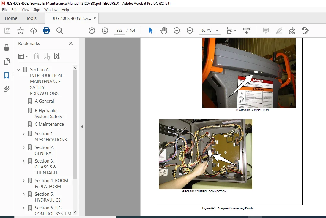
6.2 To Connect the JLG Control System Analyzer..............................321
6.3 Using the Analyzer......................................................321
6.4 Changing the Access Level of the Hand Held Analyzer.....................323
6.5 Adjusting Parameters Using the Hand Held Analyzer.......................325
6.6 Machine Setup...........................................................326
6.7 Level Vehicle Description...............................................326
6.8 Machine Personality Settings............................................335
6.9 System Test.............................................................380
Test from the Platform..................................................380
Test from the Ground Station............................................382
6.10 Analyzer Diagnostics Menu Structure....................................399
Section 7. BASIC ELECTRICAL INFORMATION & SCHEMATICS............................405
7.1 General.................................................................405
7.2 Multimeter Basics.......................................................405
Grounding...............................................................405
Backprobing.............................................................405
Min/Max.................................................................405
Polarity................................................................405
Scale...................................................................405
Voltage Measurement.....................................................405
Resistance Measurement..................................................406
Continuity Measurement..................................................406
Current Measurement.....................................................407
7.3 Checking Switches.......................................................407
Basic Check.............................................................407
Limit Switches..........................................................407
Automatic Switches......................................................408
Switch Wiring - Low Side, High Side.....................................408
7.4 Applying Silicone Dielectric Compound to Electrical Connections.........408
Installation of Dielectric Grease.......................................409
Deutsch HD, DT, DTM, DRC Series.........................................409
AMP Seal................................................................409
AMP Mate-N-Lok..........................................................410
DIN Connectors..........................................................410
Exclusions..............................................................410
7.5 AMP Connector...........................................................412
Applying Silicone Dielectric Compound to AMP Connectors.................412
Assembly................................................................412
Disassembly.............................................................414
Wedge Lock..............................................................414
Service - Voltage Reading...............................................414
7.6 Deutsch Connectors......................................................416
DT/DTP Series Assembly..................................................416
DT/DTP Series Disassembly...............................................416
HD30/HDP20 Series Assembly..............................................417
HD30/HDP20 Series Disassembly...........................................417
IMAGES PREVIEW OF THE MANUAL:
JLG 400S 460SJ Service & Maintenance Manual (3120788) – PDF DOWNLOADJLG 400S 460SJ Service & Maintenance Manual (3120788) – PDF DOWNLOAD
PLEASE NOTE:
This is the same manual used by the dealers to diagnose and troubleshoot your vehicle
You will be directed to the download page as soon as the purchase is completed. The whole payment and downloading process will take anywhere between 2-5 minutes
Need any other service / repair / parts manual, please feel free to contact [email protected] . We still have 50,000 manuals unlisted
S.M
✹
What Our Customers Say
★★★★★Live reviews from customers
Loading customer reviews...
🌟 Related Products
Discover more professional manuals for your equipment


 - PDF DOWNLOAD")
 - PDF DOWNLOAD")
 - PDF DOWNLOAD")
 - PDF DOWNLOAD")