JLG 40HT Parts Manual (3120244) – PDF Download En
Original price was: $80.00.$24.95Current price is: $24.95.
JLG 40 HT Parts Manual (3120244) – PDF Download
Description
JLG 40 HT Parts Manual (3120244) – PDF Download
TABLE OF CONTENTS:
JLG 40HT Parts Manual (3120244) – PDF Download
SUBJECT
SECTION 1 – RECOMMENDED SERVICE PARTS STOCK
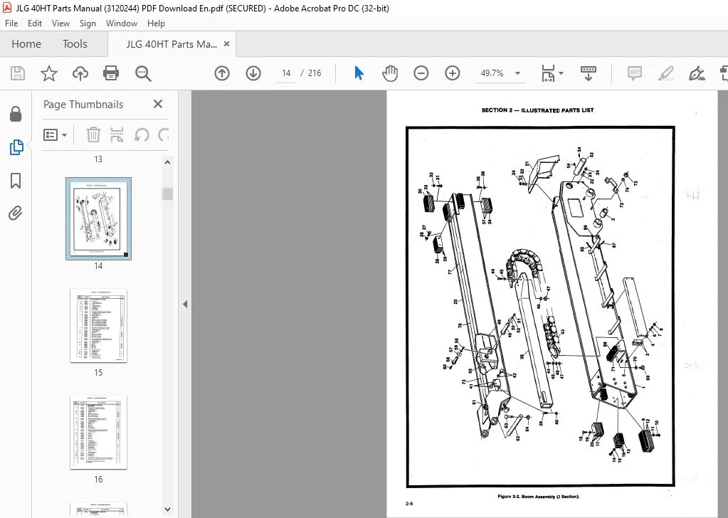
SECTION 2 – ILLUSTRATED PARTS LIST
Boom, Turntable and Horizontal Cutout Switch Installations
Boom Assembly (2 Section) ·
Telescope Cylinder Assembly (2 Section Boom)
Boom Assembly (3 Section)
Telescope Cylinder Assembly (3 Section Boom) _
Slave Cylinder Assembly
Lift Cylinder Assembly
Master Cylinder Assembly
Boom Wipers Installation (2 Section)
Boom Wipers Installation (3 Section) : ;
Platform and Control Stands Assemblies and Installations
Rotator Motor Assembly
Platform Control Box Assemblies – PQ Controllers (Circa 1983-1984)
Platform Control Box Assemblies – PQ Controllers (Circa 1984 and Newer)
Platform Control Box Assemblies – OEM Controllers
Ground Control Box Assemblies (Racine Valves)
Ground Control Box Assemblies (Vickers Valves)
Control Valves Installation (Racine Valves)
Proportional Control Valve Assembly – Outlet Section
Proportional Control Valve Assembly – Working Sections
Proportional Control Valve Assembly – Inlet (Dump) Section
Proportional Control Valve Assembly – Servo Assembly
Control Valve Assembly – Racine Bang-Bang
Control Valve Installation (Vickers Valves)
Control Valve Assembly – Vickers
Engine Components, Assemblies and Installations – Wisconsin VH4D Gas
Dual Fuel and LPG Components Installation – Wisconsin
110 Volt Generator Installation – Wisconsin
Engine Components, Assemblies and Installations – Deutz F2L511
110 Volt Generator Installation – Deutz
Motor Components, Assemblies and Installation – Electric
Gear Pump Assembly
Tandem Pump Assembly (Piston Pump Section)
Tandem Pump Assembly (Gear Pump Section)
Tanks Installation ;
Hoods Installation
Remote Lubrication and Turntable Locking Pin Installation
Rotar1 Oil Coupling Installation
Oil Cooler Installation
Swing Drive and Swing Bearing Installations
Swing Brake Assembly
Swing Motor Assembly
Swing Hub Assembly
Frame, Steering and Drive Components Installation (Double Acting Steer Cylinder)
Steer Cylinder Assembly (Double Acting)
Frame, Steering and Drive Components Installation (Single Acting Steer Cylinder)
Steer Cylinder Assembly (Single Acting)
Drive Motor Assembly
Drive Brake Assembly (Housing Length – 3 3/4″)
Drive Brake Assembly – Ausco (Housing Length – 4″)
Drive Brake Assembly – Mico (Housing Length – 4″)
Drive Hub Assembly
Tow Package (Single Acting Steer Cylinder Machines)
Placards and Decals Installation – Model 40HT
TABLE OF CONTENTS (CONTINUED)
TITLE
Hydraulic Diagram – Drive _
Hydraulic Diagram – Level
Hydraulic Diagram – Lift
Hydraulic Diagram – Manual Desc ent
Hydraulic Diagram – Pump (Racine Valves Without Steering Wheel)
Hydraulic Diagram – Pump (Racine Valves With Steering Wheel)
Hydraulic Diagram – Pump (Vickers Valves Without Steering Wheel)
Hydraulic Diagram – Pump (Vickers Valves With Steering Wheel)
Hydraulic Diagram – Rotate (Without Steering Wheel)
Hydraulic Diagram – Rotate (With Steering Wheel)
Hydraulic Diagram – Steer (Without Steering Wheel)
Hydraulic Diagram -·steer {With Steering Wheel)
Hydraulic Diagram – Swing ;
Hydraulic Diagram -Telescope
Hydraulic Diagram -Tow :
Electrical Wiring Diagrams – Racine Valves
Electrical Wiring Diagrams – Vickers Valves
SECTION 1 – RECOMMENDED SERVICE PARTS STOCK
MODEL 40HT LIFT
The following list will service each Model 40HT Lift with the most commonly used parts For further information, contact
the JLG Industries Parts Department at Area Code (717) 485-5161
Note: The following Parts are Integral of Section 2 – Illustrated Parts Ust
Limit Switch (Figure 2-1) ·
DESCRIPTION
STANDARD PARTS
Wear Pad Carrier (Figure 2-2, 2-4)
Valve Counterbalance (Figure 2-3)
Valve, Lift Cylinder (Figure 2-7)
Seal Kit Lift Cylinder (Figure 2-7)
Door Latch Basket (Figure 2-11)
Footswltch (Figure 2-11)
Contact Block, Footswitch (Figure 2-11)
Brake Disc (Figure 2-11)
Switch, Emergency, Stop Lights, Drive, Speed
(Figure 2-13, 2-14, 2-15)
Switch, Start, Horn (Figure 2-13, 2-14, 2-15)
Valve, Needle (Figure 2-16, 2-17)
Auxiliary Pump (Figure 2-26, 2-29)
Relay Prestolite (Figure 2-29)
Solenoid Hi-Engine (Figure 2-26, 2-29)
Hydraulic Filter Return (Figure 2-35)
Sensor, Level Indicator (Figure 2-36)
Seal Kit, Rotary Oil Coupling (Figure 2-38)
Seal Kit, Swing Motor (Figure 2-42)
Repair Kit, Swing Hub (Figure 2-43)
Bearing Cup (Figure 2-44)
Bearing Cone (Figure 2-44)
Seal Kit Drive Motor (Figure 2-48)
Disconnect Cap Drive Hub (Figure 2-52)
Disconnect Rod Drive Hub (Figure 2-52)
OPTIONAL/VARIABLE
Wear Pad, 1/2″ Hardware (Figure 2-2) 2 Section Boom
Wear Pad, 3/8″ Hardware, 3 Mounting Holes (Figure 2-2)
2 Section Boom
Wear Pad 3 1/2″ Length (Figure 2-2) 2 Section Boom
Wear Pad 5 1/2” Length (Figure 2-2) 2 Section Boom
Wear Pad 3/8″ Thick (Figure 2-2) 2 Section Boom
Wear Pad 7 /8″ Thick (Figure 2-2) 2 Section Boom
Wear Pad, 8″ Length, 2 Mounting Holes (Figure 2-2)
2 Section Boom
Wear Pad, 3 Mounting Holes (Figure 2-2) 2 Section Boom
Carrier Power Track (Figure 2-2) 2 Section Boom
Seal Kit, Telescope Cylinder 1681510 (Figure 2-3)
Seal Kit, Telescope Cylinder 1681583 (Figure 2-3)
Wear Pad, Base Front Bottom (Figure 2-4) 3 Section Boom
Wear Pad, Base Front Side (Figure 2-4) 3 Section Boom
Wear Pad, Base Front Top (Figure 2-4) 3 Section Boom
Retract Chair, (Figure 2-4) 3 Section Boom
Extend Chain (FlgurJ 2-4) 3 Section Boom
Carrier Power Track (Figure 2-4) 3 Section Boom
Wear _Pad, Mid Front Bottom (Figure 2-4) 3 Section Boom
Wear Pad, Mid Front Side (Figure 2-4) 3 Section Boom
Wear Pad, Fly Rear Top (Figure 2-4) 3 Section Boom
SECTION 1 – RECOMMENDED SERVICE PARTS STOCK (CONTINUED)
DESCRIPTION PART NO QTY
OPTIONAL/VARIABLE (CONTINUED)
Seal Kit, Telescope Cylinder (Figure 2-5) 3 Section Boom 2900347 1
Valve Telescope Cylinder (Figure 2-5) 3 Section Boom 4640212 1
Seal Kit, Slave Cylinder 1681518 (Figure 2-6) 3 Section Boom 2901119 1
Seal Kit, Slave Cylinder 1681722, 1681548 (Figure 2-6) 2900381 1
3 Section Boom
Valve, Slave Cylinder 1681518 (Figure 2-6) 3 Section Boom 4640269 1
Valve, Slave Cylinder 1681548 (Figure 2-6) 3 Section Boom 4640495 2
: \:= Valve, Slave Cylinder 1681722 (Figure 2-6) 3 Section Boom 4640509 2 : :: ·
Seal Kit Master Cylinder (Figure 2-S) 1681519, 1681547 2901119 1
Seal Kit Master Cyliner (Agure 2-S) 1681580 2901120 1
Brake Pad, Shaft With Internal Threads (Figure 2-11) 3340454 2
Brake Pad, Shaft With External Threads (Figure 2-11) 3340287 2
Sleeve Bearing (Figure 2-11) 0440134 2
Needle Bearing (figure 2-11) 0440120 2
Seal Kit Rotator Motor, (Figure 2-12} 2900455 1
Cable Capacity Indicator (figure 2-13) 1060138 1
Cable Capacity Indicator (Figure 2-14, 2-15) 1060168 1
Controller PQ (figure 2-13, 2-14) 1600094 2
Knob PO Tele (figure 2-13, 2-14) 2560039 1
Knob PQ Swing (Figure 2-13, 2-14) 2560040 1
Knob PO Lift (Figure 2-13, 2-14) 2560038 1
Knob PQ Drive (Figure 2-13, 2-14} 2560041 1
Switch, Emergency Stop, Engine Speed 4360199 2
(Figure 2-14, 2-15, 2-16, 2-17)
Switch, Aux Power’ Racine (Figure 2-14, 2-15, 2-16, 2-17) 4360204 2
Switch Aux Power Vickers, Choke 4360200 2
(Figure 2-14, 2-15, 2-16, 2-17)
Switch, Rotate, Steer, Tele, Platform 4360202 · 4
(Figure 2-14, 2-15, 2-16, 2-17)
Circuit Breaker 20A (Figure 2-14) 4360209 1 –
Controller OEM (Figure 2-15) Swing, Drive, Tele 1600092 2
Controller OEM (Figure 2-15) Tele 1600093 1
Switch Level, Tele, Rot , Steer (Figure 2-13) 4360077 4
‘Switch Aux Power (Figure 2-13, 2-16) 4360084 1
Switch Hom, Glow Plug, Choke (Figure 2-13) 4360114 1
Relay SPOT (Figure 2-16, 2-17) 3740049 10
Relay PB (Figure 2-16, 2-17) 3740016 2
Circuit Breaker 35A (Figure 2-16, 2-17) 4360186 1
Circuit Breaker 3A (Figure 2-16, 2-17) 4360212 1
Circuit Breaker 10A (Figure 2-16, 2-17) 4360069 3
Switch, Master (Figure 2-16, 2•17) 4360003 1
Switch, Toggle DPDT (Figure 2-16, 2-17} 4360073 1
Switch Toggle DPST (Figure 2-16, 2-17) Lift, Swing, Tele 4360074 1
Coil 12VDC Racine (Figure 2-18, 2-23, 2-24) 7000418 3
Coil FPS (Figure 2-18, 2-24) 7000558 1
Coil Hydroforce (Figure 2-18, 2-24) 7004368 1
Coil Modular Controls (Figure 2-18, 2-24) 7009745 1
Element Hydraulic Filter (Figure 2-18 ) 2120079 4
Coil 12VDC Racine (Figure 2-21, 2-23) 7000417 1
Coil 7 5 voe Racine (Figure 2-22) 1420003 1
Coil Modular Controls (Figure 2-24) 7003640 1 -—
Coll, Vickers (Figure 2-25} 7009315 1
Switch, Vacuum (Figure 2-26) 4360067 1
Solenoid, Racine Valves ( Figure 2-26, 2-29) 3740002 2
Solenoid, Vickers Valves (Figure 2-26) 3740067 r··
<f
Actuator, Single Speed, Wisconsin (Figure 2-26, 2-29) 0060020 1
Actuator, Two Speed, Wisconsin (Figure 2-26, 2-29) 0060024 ·1
1-2
SECTION 1 – RECOM MENDED SERVICE PARTS STOCK (CO NTI NUED)
DESCRIPTION
OPTI ONALNARIABLE (CONTI NUED)
Fi lter lnline (Fi gure 2-26)
Solenoid Start (Figure 2-29)
Relay Adlo (Figure 2-29)
Relay Motorcraft (Figure 2-29)
Adeco Module (Figure 2-29)
Repair Kit 3600078 (Figure 2-32)
Seal Kit 36001 26 Piston Pump (Figure 2-33)
Seal Kit 36001 26 Tandem Pu mp (Figure 2-33)
Cap, Hyd raulic Tank (Figure 2-35)
Cap and Dipstick Hydraulic Tank (Figure 2-35)
Breat her Hydraulic Tank (Figure 2-35)
Breather With Ea rs Hydraulic Ta nk (Figure 2-35)
Mechanical Fuel Gauge (Figure 2-35)
Cap, Fuel (Figure 2-35 )
Seal Kit, Ausco Swi ng Brake (Figure 2-41 )
Seal Kit ,Mico Swing Brake (Figure 2-41 )
Seal Kit Steer Cylinder Do u ble Acti ng (Fi gure 2-45)
Seal Kit Steer Cylinder Single Acti ng 3″ Bore
(Figure 2-47)
Seal Kit Steer Cylinder Single Acti ng 2 1/2″ Bore
(Figure 2-47)
Seal Kit Drive Brake 0920072 (Figure 2-49)
Seal Kit Drive Brake 0920027 Ausco (Figure 2-50)
Seal Kit Drive Brake 0920027 Mico (Figure 2-5 1 )
IMAGES PREVIEW OF THE MANUAL:
 - PDF Download")
 - PDF Download")
PLEASE NOTE:
- This is the same manual used by the dealers to diagnose and troubleshoot your vehicle
- You will be directed to the download page as soon as the purchase is completed. The whole payment and downloading process will take anywhere between 2-5 minutes
- Need any other service / repair / parts manual, please feel free to contact [email protected] . We still have 50,000 manuals unlisted
S.M