JLG 450A 450AJ Series II Service & Maintenance Manual (3121180) – PDF DOWNLOAD
TABLE OF CONTENTS:
JLG 450A 450AJ Series II Service & Maintenance Manual (3121180) – PDF DOWNLOAD
Section A. Introduction - Maintenance Safety Precautions.......................... 3
A. General.................................................................... 3
B. Hydraulic System Safety.................................................... 3
C. Maintenance................................................................ 3
Section 1. Specifications..................................................... 17
1.1 Capacities............................................................ 17
1.2 Tires................................................................. 17
1.3 Engine................................................................ 17
1.4 Specifications and Performance Data................................... 18
Reach Specifications.................................................. 18
Dimensional Data...................................................... 18
Chassis............................................................... 18
1.5 Function Speeds....................................................... 19
Machine Orientation When Doing Speed Tests............................ 19
Test Notes............................................................ 19
1.6 Torque Requirements................................................... 19
1.7 Lubrication........................................................... 21
Hydraulic Oil......................................................... 21
1.8 Major Component Weights............................................... 22
1.9 Pressure Settings - PSI (BAR)......................................... 22
1.10 Serial Number Location............................................... 22
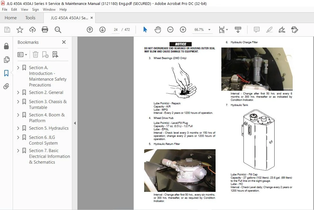
1.11 Operator Maintenance................................................. 23
1.12 Draining Propane Regulator Oil Build Up (Prior to S/N 0300137808).... 27
1.13 Propane Fuel Filter Replacement...................................... 28
Removal............................................................... 28
Installation.......................................................... 28
1.14 Propane System Pressure Relief....................................... 28
Section 2. General................................................................ 37
General....................................................................... 37
Preparation, Inspection, and Maintenance...................................... 37
Pre-Start Inspection.......................................................... 37
Pre-Delivery Inspection and Frequent Inspection............................... 37
Annual Machine Inspection..................................................... 37
Preventative Maintenance...................................................... 37
2.2 Service and Guidelines.................................................... 38
General................................................................... 38
Safety and Workmanship.................................................... 38
Cleanliness............................................................... 38
Components Removal and Installation....................................... 38
Component Disassembly and Reassembly...................................... 39
Pressure-Fit Parts........................................................ 39
Bearings.................................................................. 39
Gaskets................................................................... 39
Bolt Usage and Torque Application......................................... 39
Hydraulic Lines and Electrical Wiring..................................... 39
Hydraulic System.......................................................... 39
Lubrication............................................................... 39
Battery................................................................... 39
Lubrication and Servicing................................................. 39
2.3 Lubrication and Information............................................... 40
Hydraulic System.......................................................... 40
Hydraulic Oil............................................................. 40
Changing Hydraulic Oil.................................................... 40
Lubrication Specifications................................................ 40
2.4 Cylinder Drift Test....................................................... 41
Platform Drift............................................................ 41
Cylinder Drift............................................................ 41
2.5 Pins and Composite Bearing Repair Guidelines.............................. 41
2.6 Welding on JLG Equipment.................................................. 42
DO the Following When Welding on JLG Equipment............................ 42
DO NOT Do the Following When Welding on JLG Equipment..................... 42
Section 3. Chassis & Turntable.................................................... 51
3.1 Tires & Wheels............................................................ 51
Tire Inflation............................................................ 51
Tire Damage............................................................... 51
Pneumatic Tires........................................................... 51
Polyurethane Foam Filled Tires............................................ 51
Solid Flex Tires.......................................................... 51
Tire Replacement.......................................................... 51
Wheel Replacement......................................................... 51
Wheel Installation........................................................ 52
3.2 Torque Hub (Machines Built Before S/N 0300071527)......................... 53
Roll, Leak, and Brake Testing............................................. 53
Tightening and Torquing Bolts............................................. 53
Main Disassembly.......................................................... 54
Input Carrier Disassembly................................................. 56
Output Carrier Disassembly................................................ 57
Housing-Spindle Disassembly............................................... 58
Spindle-Brake Disassembly................................................. 59
Input Carrier Sub-Assembly................................................ 60
Output Carrier Sub-Assembly............................................... 62
Spindle-Brake Sub-Assembly................................................ 64
Housing-Spindle Sub-Assembly.............................................. 66
DW2B INTEGRAL BRAKE CHECK................................................. 66
Main Assembly............................................................. 68
3.3 Torque Hub (Machines built after S/N 0300071527).......................... 80
Roll and Leak Testing..................................................... 80
Tightening and Torquing Bolts............................................. 80
Oil Information........................................................... 80
MAIN DISASSEMBLY for “B” Drives........................................... 80
Hub-Spindle Disassembly................................................... 81
Cover Disassembly......................................................... 81
Carrier Disassembly....................................................... 81
Assemble Carrier.......................................................... 82
Cover Sub-Assembly........................................................ 84
Hub-Spindle Sub-Assembly.................................................. 85
Main Assembly............................................................. 87
Tool List................................................................. 92
3.4 Re-Aligning Torque Hub Input Coupling..................................... 93
Equipment Required........................................................ 93
Procedure................................................................. 93
3.5 Drive Motor............................................................... 93
Disassembly............................................................... 93
Inspection................................................................ 94
Assembly.................................................................. 96
Drive Motor Troubleshooting............................................... 96
3.6 Drive Motor............................................................... 97
Description............................................................... 97
Shaft Seal Replacement.................................................... 97
Loop Flushing Valve....................................................... 98
Troubleshooting........................................................... 99
Disassembly...............................................................100
Inspection................................................................104
Assembly..................................................................106
Initial Start-up Procedures...............................................111
3.7 Adjustment Procedure For Lockout Valve....................................114
3.8 Oscillating Axle Bleeding Procedure and Lockout Test......................114
Lockout Cylinder Bleeding (Early Cylinders)...............................114
Lockout Cylinder Bleeding (Ram Cylinders).................................114
Oscillating Axle Lockout Test.............................................115
3.9 Swing Bearing.............................................................115
Description...............................................................115
Removal...................................................................115
Disassembly...............................................................117
Assembly..................................................................119
Installation..............................................................119
Turntable Bearing Mounting Bolt Condition Check...........................120
Check Frame To Bearing Bolts..............................................120
Wear Tolerance............................................................121
3.10 Swing Motor..............................................................122
Preparation Before Disassembly............................................122
Removal...................................................................124
Preparation Before Disassembly............................................124
Disassembly and Inspection................................................125
Assembly..................................................................132
One Piece Stator Assembly.................................................138
Two Piece Stator Assembly.................................................139
Final Checks..............................................................139
Installation..............................................................139
3.11 Semi-Track...............................................................140
Testing...................................................................140
Removing..................................................................140
Normal Wear...............................................................140
Adjustment................................................................140
3.12 Generator................................................................144
Every 250 hours...........................................................144
Every 500 hours...........................................................144
Overload Protection.......................................................144
Brushes and Slip Rings....................................................144
3.13 Ford EFI Engine..........................................................146
Performing Diagnostics....................................................146
EFI Diagnostics...........................................................146
ECM and Sensors...........................................................146
Intake Air Temperature (IAT) Sensor.......................................150
Manifold Absolute Pressure (MAP) Sensor...................................150
Engine Control Module (ECM)...............................................150
ECM Inputs/Outputs........................................................151
Throttle Position (TP) Sensor.............................................151
3.14 Circuit Testing Tools....................................................152
Electrostatic Discharge Damage............................................152
Fuel System...............................................................152
3.15 Deutz Engine.............................................................156
Checking Oil Level........................................................156
Changing Engine Oil.......................................................156
Changing Oil Filter.......................................................157
Replacing Fuel Filter.....................................................157
Cleaning Fuel Strainer....................................................157
3.16 Deutz EMR 2 (S/N 85332 to Present).......................................158
3.17 GM Engine General Maintenance............................................170
Drive Belt Maintenance....................................................170
Engine Electrical System Maintenance......................................170
Checking/Filling Engine Oil Level.........................................170
Changing Engine Oil.......................................................171
Coolant Fill Procedure - Dual Fuel Engine.................................171
3.18 GM Engine Dual Fuel System...............................................172
Fuel Filter...............................................................172
Electric Lock Off.........................................................172
EPR Assembly..............................................................173
Low Pressure Regulator (LPR)..............................................173
Air Fuel Mixer............................................................174
Electronic Throttle Control (ETC).........................................174
Engine Control Module.....................................................175
Heated Exhaust Gas Oxygen Sensor..........................................175
Gasoline Multi Point Fuel Injection System (MPFI).........................175
Gasoline Fuel Pump........................................................176
Gasoline Pressure And Temperature Sensor Manifold.........................176
Fuel Filter...............................................................176
Fuel Injector Rail........................................................176
Fuel Injector.............................................................176
3.19 GM Engine Fuel System Repair.............................................176
Propane Fuel System Pressure Relief.......................................176
Propane Fuel System Leak Test.............................................177
Propane Fuel Filter Replacement...........................................177
Removal...................................................................177
Installation..............................................................177
Electronic Pressure Regulator (EPR) Assembly Replacement..................178
Temperature Manifold Absolute Pressure (TMAP) Sensor......................179
Electronic Throttle Control Replacement...................................179
MIXER REPLACEMENT.........................................................180
Coolant Hose Replacement..................................................180
Vapor Hose Replacement....................................................181
Engine Control Module Replacement.........................................181
Heated Exhaust Gas Oxygen Sensor Replacement..............................181
3.20 GM Engine LPG Fuel System Diagnosis......................................182
Fuel System Description...................................................182
Diagnostic Aids...........................................................182
3.21 Perkins Engine General Maintenance.......................................197
Replacing the Engine Crankcase Breather...................................197
Engine Oil Level - Check..................................................197
Engine Oil and Filter - Change............................................197
Fuel Filter/Water Separator...............................................199
Setting Actuator..........................................................200
Speed Sensor Installation.................................................201
3.22 Engine Radiator Fill Procedure - Perkins & Caterpillar...................201
3.23 DGC DIAGNOSTIC SUPPORT AND TROUBLE CODE DEFINITIONS......................203
Section Layout............................................................203
Fault Code Broadcast......................................................205
Diagnostic Trouble Codes..................................................205
CAN.......................................................................205
MIL Output................................................................205
Diagnostic Calibration Configuration and Corrective Actions...............206
Fault/Diagnostic Trouble Code Interaction.................................207
DBW Diagnostic Test.......................................................209
3.24 Diagnostic Trouble Code Fault Descriptions...............................212
DTC 116- ECT Higher Than Expected Stage 1.................................212
DTC 117- ECT/CHT Low Voltage..............................................213
DTC 118- ECT/CHT High Voltage.............................................215
DTC 122- TPS1 Signal Voltage Low..........................................217
DTC 123- TPS1 Signal Voltage High.........................................219
DTC 217- ECT Higher Than Expected 2.......................................221
DTC 219- RPM Higher Than Max Allowed Governed Speed.......................222
DTC 336- Crank Signal Input Noise.........................................223
DTC 337- Loss of Crank Input Signal.......................................225
DTC 521- Oil Pressure Sender/Switch High Pressure.........................226
DTC 524- Oil Pressure Low.................................................229
DTC 562- Battery Voltage (VBat) Low.......................................233
DTC 563- Battery Voltage (VBat) High......................................235
DTC 601- Microprocessor Failure - FLASH...................................237
DTC 604- Microprocessor Failure - RAM.....................................239
DTC 606- Microprocessor Failure - COP.....................................241
DTC 642- 5 Volt External Low Voltage......................................243
DTC 643- 5 Volt External High Voltage.....................................244
DTC 1612- Microprocessor Failure - RTI 1..................................245
DTC 1613- Microprocessor Failure - RTI 2..................................245
DTC 1614- Microprocessor Failure - RTI 3..................................247
DTC 1615- Microprocessor Failure - A/D....................................249
DTC 1616- Microprocessor Failure - interrupt..............................251
DTC 1625- CAN J1939 Shutdown Request......................................253
DTC 1626- CAN J1939 Transmit (Tx) Fault...................................254
DTC 1627- CAN J1939 Receive (Rx) Fault....................................255
DTC 1628- CAN Address Conflict Failure....................................256
DTC 1629- J1939 TSC1 Message Receipt Loss.................................258
DTC 1652- TPS1 Loss of Communications.....................................259
DTC 2111- Unable to Reach Lower TPS.......................................260
DTC 2112- Unable to Reach Higher TPS......................................262
DTC 9999- Throttle Actuator Failsafe Spring Failure.......................263
DTC to SPN/FMI Table......................................................264
Section 4. Boom & Platform........................................................267
4.1 Boom Maintenance..........................................................267
Removal of Boom Assembly..................................................267
Disassembly of Main Boom..................................................268
Inspection................................................................268
Assembly of Main Boom.....................................................269
Installation of Boom Assembly.............................................269
4.2 Rotator...................................................................274
Theory of Operation.......................................................274
Disassembly and Inspection................................................274
Assembly and Testing......................................................274
4.3 Rotary Actuator (S/N 0300130812 and 1300006433 to Present)................277
Theory of Operation.......................................................277
Required Tools............................................................277
Disassembly...............................................................280
Inspection................................................................284
Assembly..................................................................284
Installing Counterbalance Valve...........................................289
Section 5. Hydraulics.............................................................291
5.1 Cylinder Repair -USA Manufactured Only....................................291
Disassembly...............................................................291
Cleaning and Inspection...................................................312
Assembly..................................................................313
5.2 Hydraulic Pump (Gear).....................................................316
Disassembly...............................................................316
Inspect Parts For Wear....................................................318
General Information.......................................................319
Reverse Shaft Rotation of Pump............................................319
Assembly..................................................................319
Placing Pump Back Into Service............................................322
5.3 Variable Pump.............................................................322
Ports and Pressure Gauges.................................................322
NFPE Control..............................................................322
Removal and Installation of FNR and NFPE Modules..........................323
Removal and Installation of FNR and NFPE Control Orifices.................323
Charge Relief Valve.......................................................323
Shaft Seal and Shaft Replacement..........................................326
Charge Pump...............................................................328
5.4 Hydraulic Component Start-Up Procedures and Recommendations...............330
5.5 Pressure Setting Procedure................................................332
Bang-Bang Main Relief.....................................................332
Steer.....................................................................332
Platform Level Up.........................................................332
Platform Level Down.......................................................332
Articulating Jib..........................................................332
Proportional Main Relief..................................................332
Lift Down.................................................................332
Swing.....................................................................332
Section 6. JLG Control System.....................................................337
6.1 Introduction..............................................................337
6.2 Connect JLG Control System Analyzer.......................................339
6.3 Using Analyzer............................................................339
6.4 Changing Hand Held Analyzer Access Level..................................341
6.5 Adjusting Parameters Using the Hand Held Analyzer.........................343
6.6 Machine Setup.............................................................343
6.7 Machine Personality Settings..............................................355
6.8 System Test...............................................................375
Test from Platform........................................................375
Test from the Ground Station..............................................377
Section 7. Basic Electrical Information & Schematics..............................417
7.1 General...................................................................417
7.1 Multimeter Basics.........................................................417
Grounding.................................................................417
Backprobing...............................................................417
Min/Max...................................................................417
Polarity..................................................................417
Scale.....................................................................417
Voltage Measurement.......................................................417
Resistance Measurement....................................................418
Continuity Measurement....................................................418
Current Measurement.......................................................419
7.2 Applying Silicone Dielectric Compound to Electrical Connections...........419
7.3 AMP Connector.............................................................420
Applying Silicone Dielectric Compound to AMP Connectors...................420
Assembly..................................................................420
Disassembly...............................................................422
Wedge Lock................................................................422
7.4 Deutsch Connectors........................................................424
DT/DTP Series Assembly....................................................424
DT/DTP Series Disassembly.................................................424
HD30/HDP20 Series Assembly................................................425
HD30/HDP20 Series Disassembly.............................................425
IMAGES PREVIEW OF THE MANUAL:
JLG 450A 450AJ Series II Service & Maintenance Manual (3121180) – PDF DOWNLOADJLG 450A 450AJ Series II Service & Maintenance Manual (3121180) – PDF DOWNLOAD
PLEASE NOTE:
This is not a physical manual but a digital manual – meaning no physical copy will be couriered to you. The manual can be yours in the next 2 mins as once you make the payment, you will be directed to the download page IMMEDIATELY.
This is the same manual used by the dealers inorder to diagnose your vehicle of its faults.
Require some other service manual or have any queries: please WRITE to us at [email protected]
s.m
✹
What Our Customers Say
★★★★★Live reviews from customers
Loading customer reviews...
🌟 Related Products
Discover more professional manuals for your equipment


 - PDF DOWNLOAD")
 - PDF DOWNLOAD")
 - PDF DOWNLOAD")
 - PDF DOWNLOAD")