
JLG 600A / 600AJ Boom Lift Illustrated Parts Manual 3121177 Rev AJ
Original price was: $34.95.$20.95Current price is: $20.95.
Complete illustrated parts catalog for JLG 600A and 600AJ articulating boom lifts — document 3121177, Revision AJ. Exploded-view figures with itemized part numbers covering the frame, turntable, boom, platform, cylinders, hydraulics, electrical harnesses, decals, and every major assembly across serial range 0300069000–0300087000.
Description
JLG 600A / 600AJ Illustrated Parts Manual — Document 3121177, Revision AJ
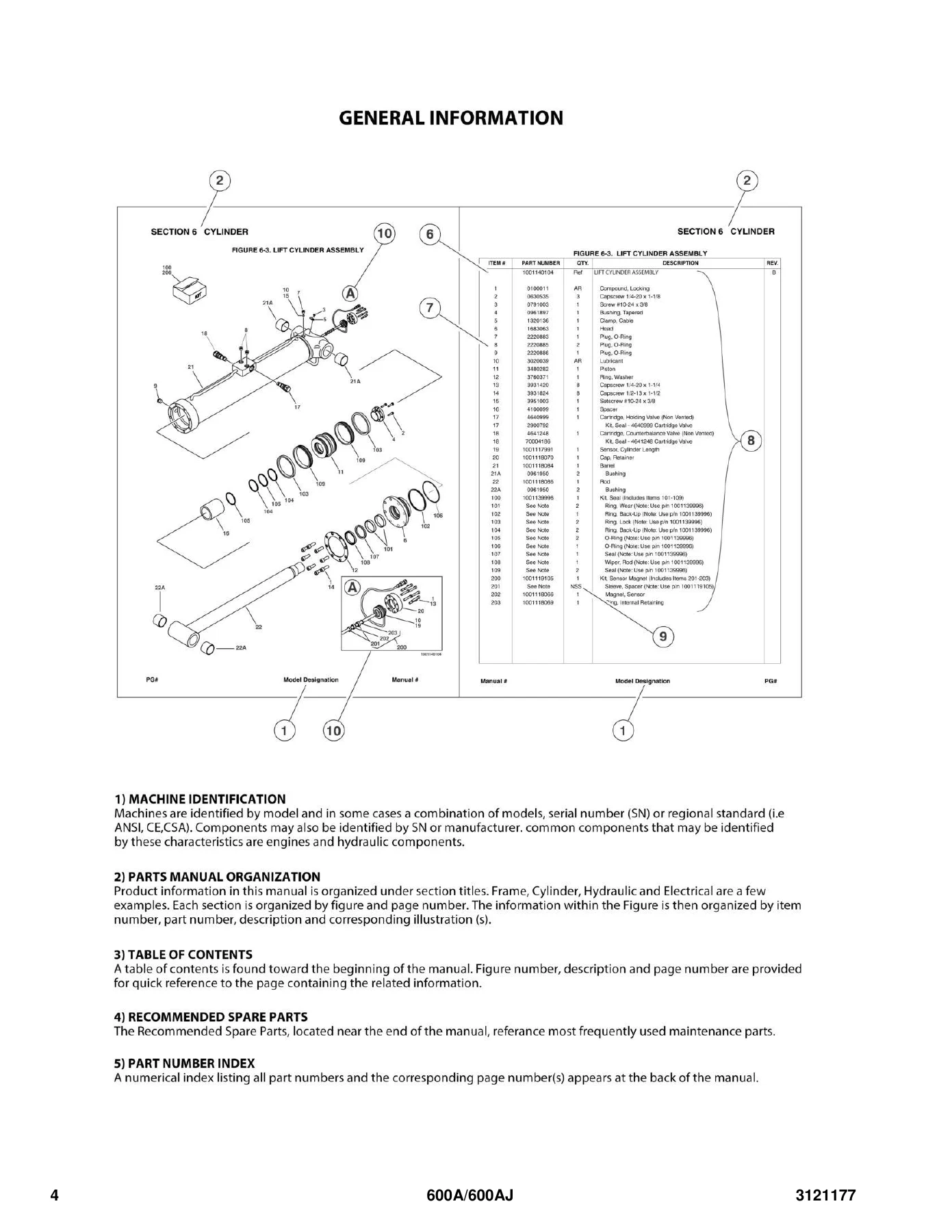
This is the full illustrated parts manual for the JLG 600A and 600AJ articulating boom lifts, published under document number 3121177 at revision level AJ. Running close to 400 pages, the catalog pairs detailed exploded-view illustrations with itemized part number tables for every major assembly on these machines — from the frame and axles up through the turntable, boom sections, rotators, and platform. If you need to order a replacement seal kit for a lift cylinder, track down a specific hydraulic fitting, or confirm the correct cartridge valve for a main valve block, this JLG 600A 600AJ parts manual gives you the figure number, item number, JLG part number, quantity, and description needed to get the right component on the first attempt.
The coverage spans machines built within serial number range 0300069000 through 0300087000 and addresses all three engine variants offered for the 600A and 600AJ: Caterpillar, Deutz, and Ford LRG-425. Because part numbers changed frequently across the production run, the catalog is organized so you can match your machine’s serial number to the correct figure before ordering. Dedicated breakdowns separate original equipment from service replacement components, so you always know which revision of an assembly you are dealing with.
File Details
- Manual type: Illustrated Parts Manual (IPL / parts catalog)
- Brand: JLG
- Models covered: 600A, 600AJ
- Document number: 3121177
- Revision: AJ
- Language: English
- Page count: Approximately 398 pages
- File format: PDF
- Serial number coverage: 0300069000 through 0300087000
Chapters Covered
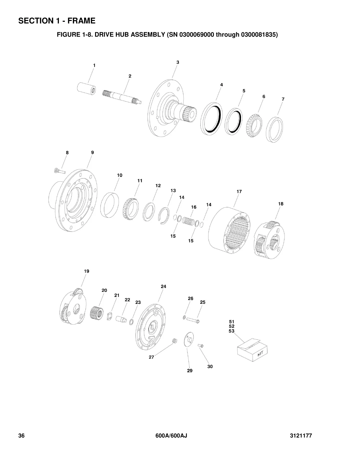
- Section 1 — Frame: 2WD and 4WD front axle and steering installations, 4WS rear steering installations, tire and wheel drive installations, drive hub assembly, drive hub/brake assembly, 2WD and 4WD drive motor assemblies, frame-mounted drive valves and shields, tow package installation.
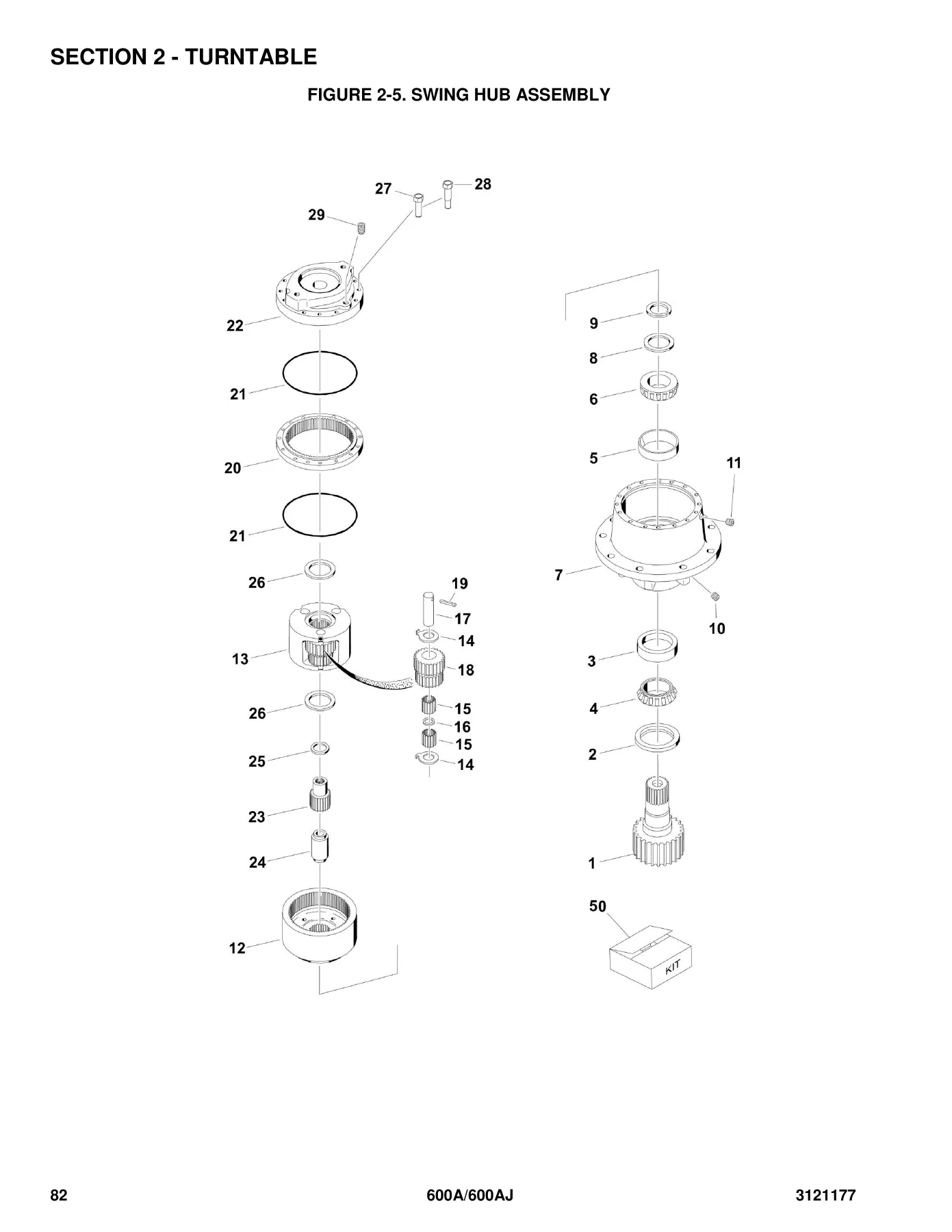
- Section 2 — Turntable: Control valves installations, main valve block assembly, accessory valve assemblies, swing drive/turntable bearing and lock installations, swing hub assembly, swing motor assembly, Caterpillar engine installation, Deutz engine installation, Ford LRG-425 engine installation, dual fuel installation, piston pump assembly, gear pump assembly, tank installations, rotary coupling installations, ground control box assemblies, electrical options installations, engine tray jack installations, hoods installations, 2500W generator installations, 7500W SkyPower generator installations.
- Section 3 — Boom: Booms and cylinders installation (600A and 600AJ), tower boom assemblies, main boom assemblies, rotator assemblies for front entry and side entry platforms, boom-mounted valves and switches installation.
- Section 4 — Platform: Platform assemblies (front entry and side entry), platform components installation for fall arrest platform, platform console assembly, controller assemblies for lift/swing and drive/steer, soft touch system installation, platform padding installation.
- Section 5 — Cylinder: Axle lockout cylinder assembly, platform level cylinder assembly, level cylinder assembly (platform slave), level cylinder assembly (upright), lift cylinder assembly (articulating jib), lift cylinder assembly (main boom), lift cylinder assembly (tower boom), master cylinder assembly, steer cylinder assembly, telescope cylinder assembly (main boom and tower boom), cylinder bellows installation.
- Section 6 — Hydraulic: Drive hydraulic diagrams for 2WD/2WS and 4WD/2WS, oscillating axle hydraulic diagram, standard hydraulic diagrams, hydraulic diagram list.
- Section 7 — Electrical: Electrical diagram list, electrical schematics for Deutz, Caterpillar, and Ford engines, harness components installation.
- Section 8 — Decals: Decal installation for ANSI spec machines and country-specific specs.
- Section 9 — Recommended Service Parts Stock: Standard parts list and variable parts list.
- Section 10 — Special Options: Special equipment and option installations.
- Part Number Index: Numerical index listing all part numbers with their corresponding page numbers.
What sets this catalog apart from a generic service manual is its part-number-first organization. Every figure is built around a callout table that ties each illustrated component to a specific JLG part number, quantity, and description — so a technician, parts manager, or fleet mechanic can identify a component visually, cross-reference the part number, and place an order without guesswork. The manual also flags non-serviced parts (marked NSS or NLA), assemblies with no separately available components, and breakdowns that carry a Ref quantity rather than a stocked part.
How This JLG 600A 600AJ Parts Manual Helps You Order the Right Part
The biggest risk when repairing a boom lift is ordering the wrong component — a seal kit that doesn’t match the cylinder revision on your machine, a valve cartridge that fits a different serial range, or a hose assembly that routes differently on a 2WD versus 4WD machine. This 600A / 600AJ illustrated parts manual removes that risk by showing you exactly which figure and item number correspond to your machine’s configuration. The parts lists include Rev-level notes, SN range callouts, and separate line items for original equipment versus service replacement parts, so you can confirm fitment before money changes hands.
Among the most valuable sections are the drive hub and drive motor assemblies, which include detailed exploded views of the coupling, input shaft, spindle, ring gear, secondary carrier, primary carrier, sun gear, disengage plunger, and hub cover — with a dedicated seal kit and bearing kit listed so you don’t have to piece together individual O-rings and retaining rings. The cylinder section is equally deep, breaking down the axle lockout, platform level, upright level, jib lift, main boom lift, tower boom lift, master, steer, and telescope cylinders with their barrels, rods, pistons, heads, cartridges, and complete seal kits. For hydraulic troubleshooting and hose replacement, the drive hydraulic diagrams and standard hydraulic diagrams give you a full map of fittings, hoses, valves, and quick-couplings across the 2WD/2WS and 4WD/2WS configurations.
Serial Number and Engine Variation Coverage
JLG built the 600A and 600AJ across a long production window, and this manual reflects the differences by splitting many figures into SN-range-specific sections. For example, the 2WD front axle and steering installation is broken into two figures — one for machines 0300069000 through 0300081835, another for 0300081836 through 0300087000 — because the axle weldment, lockout cylinder, and pin hardware changed between those ranges. Similarly, the Deutz engine installation is split at SN 0300077490, the Ford LRG-425 installation is split at SN 0300079888, and the Caterpillar installation is split at SN 0300084829. Generator installations, rotary coupling installations, hood installations, decal kits, and even the ground control box assemblies all carry SN-specific variants. Before ordering, cross-reference your machine’s serial number against the applicable figure heading to confirm you’re looking at the right breakdown.
Who This Manual Is For
This illustrated parts manual is built for anyone who maintains, repairs, or restores a JLG 600A or 600AJ boom lift: fleet maintenance departments, independent equipment mechanics, rental companies keeping machines in service, and owners who prefer to source parts themselves rather than through a dealer counter. Because it is organized by assembly rather than by procedure, it works equally well as a counter reference for parts staff and as a bench reference for technicians disassembling a drive hub, cylinder, or swing drive. The part number index at the back makes it fast to look up a known part number and jump straight to the page that shows where it goes.
Get the JLG 600A 600AJ Illustrated Parts Manual — Instant PDF Delivery
With this JLG 600A / 600AJ parts catalog in hand, you can identify and order the correct components for axle and steering assemblies, drive hubs and motors, control and main valve blocks, swing drive and swing hub, engine and pump installations, rotary couplings, hydraulic hose and fitting runs, boom and cylinder assemblies, rotator assemblies, platform consoles and controllers, electrical harnesses, and decal sets. Correct part identification matters on a boom lift — a wrong seal or valve cartridge can mean a machine sitting out of service for days while the right part is re-ordered. This 3121177 Rev AJ parts manual eliminates that downtime by showing exactly which part number belongs to your machine’s configuration and serial range. Delivered as an instant PDF download after payment, it arrives on any device, requires no shipping, and can be printed and kept on the service truck or in the shop for quick reference. The manual is also useful as a permanent reference for part-number verification during inspections, rebuilds, and warranty documentation.
Reviews
There are no reviews yet.