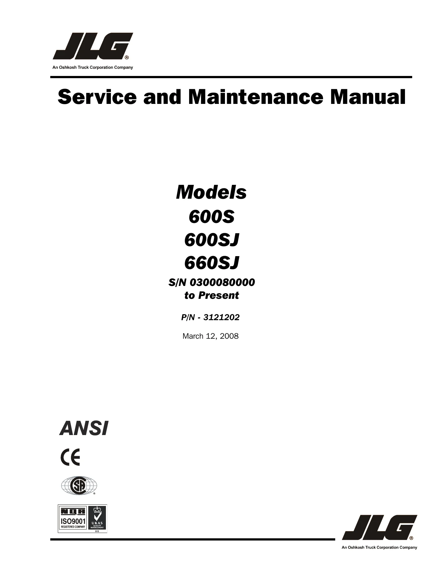
JLG 600S 600SJ 660SJ Boom Lift Service and Maintenance Manual – P/N 3121202
$29.95 Original price was: $29.95.$17.95Current price is: $17.95.
Factory Service and Maintenance Manual for JLG 600S, 600SJ, and 660SJ telescopic boom lifts, S/N 0300080000 to Present. Covers chassis, boom, hydraulics, control system, and electrical schematics. Instant PDF download.
Description
JLG 600S 600SJ 660SJ Boom Lift Service and Maintenance Manual
This is the complete JLG 600S 600SJ 660SJ Boom Lift Service and Maintenance Manual, document number 3121202, covering machines from serial number 0300080000 to present. Originally issued October 15, 2004 and revised through March 12, 2008, this manual gives technicians the full factory-level detail needed to service, troubleshoot, and repair these telescopic boom lifts.
File Details
- Manual Type: Service and Maintenance Manual
- Brand/Models: JLG 600S, 600SJ, 660SJ
- Language: English
- Page Count: 304 pages
- File Format: PDF
- Document Number: 3121202
- Revision Date: March 12, 2008
- Serial Number Range: 0300080000 to Present
Chapters Covered
- Introduction – Maintenance Safety Precautions
- Section 1 – Specifications
- Capacities, Component Data, Engine Data (Ford LRG-425, Deutz F4M1011F/F4M2011, Deutz D2011L04, Caterpillar 3044C, GM 3.0L)
- Performance Data, Machine Weight, Dimensional Data
- Function Speeds, Torque Requirements, Lubrication
- Pressure Settings, Cylinder Specifications
- Major Component Weights, Critical Stability Weights
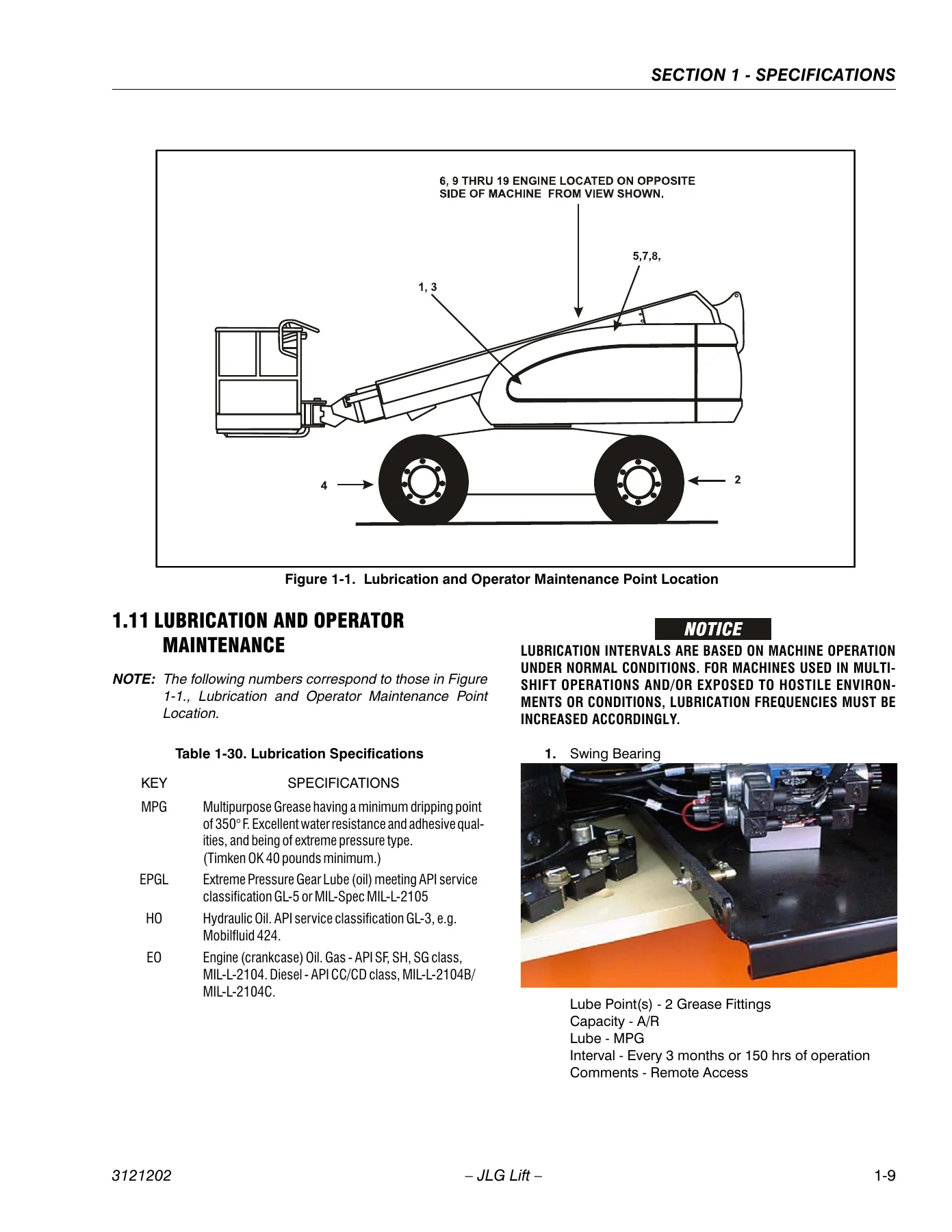
- Lubrication and Operator Maintenance, Serial Number Locations
- Section 2 – General
- Machine Preparation, Inspection, and Maintenance
- Service and Guidelines, Lubrication and Information
- Cylinder Drift Test, Pins and Composite Bearing Repair Guidelines
- Welding on JLG Equipment
Complete PDF Bookmark TreeComplete Bookmarks
The complete bookmarks in the “JLG 600S 600SJ 660SJ Boom Lift Service and Maintenance Manual – P/N 3121202” are as follows:
+Section A. Introduction – Maintenance Safety Precautionsp. 3
A Generalp. 3B Hydraulic System Safetyp. 3C Maintenancep. 3+Section 1. Specificationsp. 17
1.1 Capacitiesp. 17+1.2 Component Datap. 17
Engine Datap. 17Drive Systemp. 18Tiresp. 18Swing Systemp. 18Auxiliary Power Pumpp. 18Hydraulic Filtersp. 18+1.3 Performance Datap. 19
Machine Weight (Approximate)p. 19Dimensional Datap. 19+1.4 Function Speedsp. 20
Machine Orientation When Doing Speed Testsp. 20Test Notesp. 201.5 Torque Requirementsp. 21+1.6 Lubricationp. 21
Ford Engine Oil Specificationsp. 21Deutz Engine Oil Specificationsp. 21Hydraulic Oilp. 221.7 Pressure Settingsp. 221.8 Cylinder Specificationsp. 231.9 Major Component Weightsp. 231.10 Critical Stability Weightsp. 24+1.11 Lubrication and Operator Maintenancep. 25
Draining Oil Build Up From The Propane Regulatorp. 29Propane Fuel Filter Replacementp. 30Propane Fuel System Pressure Reliefp. 311.12 Serial Number Locationsp. 31+Section 2. Generalp. 35
+2.1 Machine Preparation, Inspection, and Maintenancep. 35
Generalp. 35Preparation, Inspection, and Maintenancep. 35Pre-Start Inspectionp. 35Pre-Delivery Inspection and Frequent Inspectionp. 35Annual Machine Inspectionp. 35Preventative Maintenancep. 35+2.2 Service and Guidelinesp. 36
Generalp. 36Safety and Workmanshipp. 36Cleanlinessp. 36Components Removal and Installationp. 37Component Disassembly and Reassemblyp. 37Pressure-Fit Partsp. 37Bearingsp. 37Gasketsp. 37Bolt Usage and Torque Applicationp. 37Hydraulic Lines and Electrical Wiringp. 37Hydraulic Systemp. 37Lubricationp. 38Batteryp. 38Lubrication and Servicingp. 38+2.3 Lubrication and Informationp. 38
Hydraulic Systemp. 38Hydraulic Oilp. 38Changing Hydraulic Oilp. 39Lubrication Specificationsp. 39+2.4 Cylinder Drift Testp. 39
Platform Driftp. 39Cylinder Driftp. 392.5 Pins and Composite Bearing Repair Guidelinesp. 40+2.6 Welding on JLG Equipmentp. 40
Do the Following When Welding on JLG Equipmentp. 40Do NOT Do the Following When Welding on JLG Equipmentp. 40+Section 3. Chassis & Turntablep. 49
+3.1 Drive Torque hubp. 49
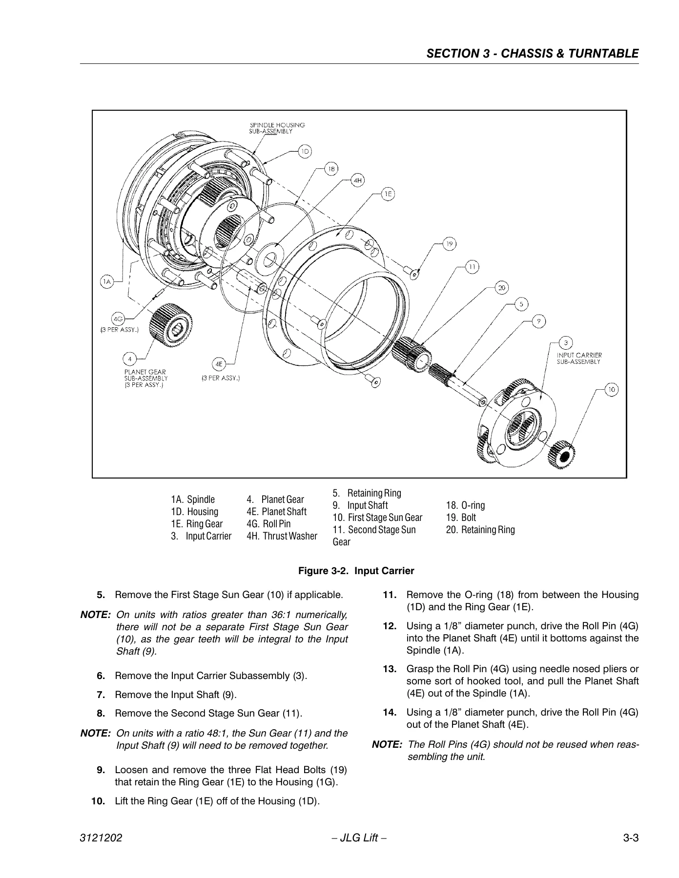
Roll, Leak and Brake Testingp. 49Tightening and Torquing Boltsp. 49Main Disassemblyp. 50Input Carrier Disassemblyp. 53Hub-Spindle Disassemblyp. 54Spindle-Brake Disassemblyp. 55Cover Disassemblyp. 57Input Carrier Sub-Assemblyp. 58Output Planet Gear Sub-Assemblyp. 58Spindle – Brake Sub-Assemblyp. 58Hub-Spindle Sub-Assemblyp. 59Cover Sub-Assemblyp. 60Main Assemblyp. 60Integral Brake Checkp. 60+3.2 Free Wheeling Optionp. 64
To Disengage Drive Motors and Brakes (Free Wheel) for Towing, etc.p. 64To Engage Drive Motors and Brakes (Normal Operation)p. 64+3.3 Drive Motor (S/N 75606 to Present)p. 64
Descriptionp. 64Shaft Seal Replacementp. 65Loop Flushing Valvep. 66Troubleshootingp. 67Disassemblyp. 68Inspectionp. 72Assemblyp. 74Initial Start-up Proceduresp. 79+3.4 Oscillating Axle Bleeding Procedure and Lockout Testp. 80
Lockout Cylinder Bleedingp. 80Oscillating Axle Lockout Testp. 803.5 Steer Adjustmentsp. 81+3.6 Swing Hubp. 82
Adjustment Proceduresp. 82+3.7 Swing Bearingp. 82
Turntable Bearing Mounting Bolt Condition Checkp. 82Wear Tolerancep. 83Swing Bearing Replacementp. 85Swing Bearing Torque Valuesp. 86+3.8 Swing Brake – Micop. 87
Disassemblyp. 87Inspectionp. 87Assemblyp. 87+3.9 Tires & Wheelsp. 89
Tire Inflationp. 89Tire Damagep. 89Tire Replacementp. 89Wheel Replacementp. 89Wheel Installationp. 893.10 Rotary Couplingp. 90+3.11 Generatorp. 95
Every 250 hoursp. 95Every 500 hoursp. 95Overload Protectionp. 96Inspecting Brushes, Replacing Brushes, and Cleaning Slip Ringsp. 963.12 Spark Arrester Cleaning Instructionsp. 983.13 Glow Plugsp. 98+3.14 Ford EFI Enginep. 98
Performing Diagnosticsp. 98ECM/EPM and Sensorsp. 99Fuel Systemp. 104+3.15 Ford LPG Systemp. 109
Descriptionp. 109Regulatorp. 109Megajectorp. 109Mixerp. 109Lockoff Solenoidp. 109Megajector Diagnostic Code Descriptionsp. 111Changing from Gasoline to LP Gasp. 112Changing from LP Gas to Gasolinep. 1123.16 Deutz EMR 2 (S/N 84827 to Present)p. 120+3.17 Bio Fuel in Deutz Enginesp. 133
Generalp. 133Bio Fuelp. 133Biological Contamination In Fuelsp. 134+3.18 GM Engine General Maintenancep. 135
Maintenance of the Drive Beltp. 135Engine Electrical System Maintenancep. 135Checking/Filling Engine Oil Levelp. 135Changing The Engine Oilp. 136Coolant Fill Procedure – Dual Fuel Enginep. 136+3.19 GM Engine Dual Fuel Systemp. 137
Fuel Filterp. 138Electric Lock Offp. 138EPR Assemblyp. 138Low Pressure Regulator (LPR)p. 139Air Fuel Mixerp. 139Electronic Throttle Control (ETC)p. 140Engine Control Modulep. 140Heated Exhaust Gas Oxygen Sensorp. 141Gasoline Multi Point Fuel Injection System (MPFI)p. 141Gasoline Fuel Pumpp. 141Gasoline Pressure And Temperature Sensor Manifoldp. 141Fuel Filterp. 142Fuel Injector Railp. 142Fuel Injectorp. 142+3.20 GM Engine Fuel System Repairp. 142
Propane Fuel System Pressure Reliefp. 142Propane Fuel System Leak Testp. 142Propane Fuel Filter Replacementp. 143Electronic Pressure Regulator (EPR) Assembly Replacementp. 143Temperature Manifold Absolute Pressure (TMAP) Sensorp. 145Electronic Throttle Control Replacementp. 145MIXER REPLACEMENTp. 146Coolant Hose Replacementp. 147Vapor Hose Replacementp. 147Engine Control Module Replacementp. 147Heated Exhaust Gas Oxygen Sensor Replacementp. 147+3.21 GM Engine LPG Fuel System Diagnosisp. 148
Fuel System Descriptionp. 148Diagnostic Aidsp. 148+Section 4. Boom & Platformp. 163
4.1 Boom Rope Torquing Proceduresp. 163+4.2 Wear Padsp. 164
Main Boomp. 164+4.3 Wire Ropep. 164
Inspectionp. 164Three Month Inspectionp. 165Seven Year Inspectionp. 165Replacement Criteriap. 165+4.4 Boom Maintenancep. 165
Removalp. 165Disassembly of Boom Sectionsp. 167Inspectionp. 171Assemblyp. 173Installationp. 176+4.5 Articulating Jib Boomp. 177
Removalp. 177Disassemblyp. 177Inspectionp. 177Assemblyp. 1784.6 Limit Switches and Cam Valve Adjustmentp. 178+4.7 Platformp. 181
Platform Sections Replacementp. 181+4.8 Rotator – Helacp. 181
Disassemblyp. 181Inspectionp. 183Assemblyp. 1834.9 Foot Switch Adjustmentp. 184+Section 5. Hydraulicsp. 187
+5.1 Cylinders – Theory of Operationp. 187
Systems Incorporating Double Acting Cylindersp. 187Systems Incorporating Holding Valvesp. 187+5.2 Cylinder Checking Procedurep. 187
Cylinders Without Counterbalance Valves – Master Cylinder and Steer Cylinderp. 187Cylinders With Single Counterbalance Valvep. 187Cylinders With Dual Counterbalance Valvesp. 188+5.3 Cylinder Removal and Installationp. 188
Main Boom Telescope Cylinder Removalp. 188Main Boom Telescope Cylinder Installationp. 189Main Boom Lift Cylinder Removalp. 190Main Boom Lift Cylinder Installationp. 190+5.4 Cylinder Repairp. 190
Disassemblyp. 190Cleaning and Inspectionp. 192Assemblyp. 193+5.5 Variable Displacement pump (M46 series)p. 204
Troubleshootingp. 204Inspections and Adjustmentsp. 208Minor Repair and Replacementp. 211+5.6 Valves – Theory of Operationp. 215
Solenoid Control Valve – Rexrothp. 215Relief Valvesp. 215+5.7 Pressure Setting Proceduresp. 216
Main Relief, Steer, Swing and Lift Downp. 216Platform Levelp. 216Articulating Jib Boom (If Equipped)p. 2164 Wheel Steer (If Equipped)p. 2205.8 Hydraulic Component Start-Up Procedures and Recommendationsp. 2205.9 Hydraulic Pump W/hayes Pump Drive Coupling Lubricationp. 221+Section 6. JLG Control Systemp. 223
6.1 Introductionp. 2236.2 To Connect the JLG Control System Analyzerp. 2256.3 Using the Analyzerp. 2256.4 Changing the Access Level of the Hand Held Analyzerp. 2276.5 Adjusting Parameters Using the Hand Held Analyzerp. 2296.6 Machine Setupp. 2306.7 Level Vehicle Descriptionp. 2306.8 Machine Personality Settingsp. 2396.9 Analyzer Diagnostics Menu Structurep. 271+Section 7. Basic Electrical Information & Schematicsp. 277
7.1 Generalp. 277+7.2 Multimeter Basicsp. 277
Groundingp. 277Backprobingp. 277Min/Maxp. 277Polarityp. 277Scalep. 277Voltage Measurementp. 277Resistance Measurementp. 278Continuity Measurementp. 278Current Measurementp. 2797.3 Applying Silicone Dielectric Compound to Electrical Connectionsp. 279+7.4 AMP Connectorp. 280
Applying Silicone Dielectric Compound to AMP Connectorsp. 280Assemblyp. 280Disassemblyp. 282Wedge Lockp. 282Service – Voltage Readingp. 282+7.5 Deutsch Connectorsp. 284
DT/DTP Series Assemblyp. 284DT/DTP Series Disassemblyp. 284HD30/HDP20 Series Assemblyp. 285HD30/HDP20 Series Disassemblyp. 285 - Section 3 – Chassis & Turntable
- Drive Torque Hub Disassembly, Assembly and Testing
- Free Wheeling Option, Drive Motor Service and Troubleshooting
- Oscillating Axle Bleeding Procedure, Steer Adjustments
- Swing Hub, Swing Bearing, Swing Brake – Mico
- Tires & Wheels, Rotary Coupling, Generator
- Ford EFI Engine Diagnostics, ECM/EPM and Sensors, Fuel System
- Ford LPG System
- Section 4 – Boom & Platform
- Boom Rope Torquing Procedures, Wear Pads, Wire Rope Inspection
- Boom Maintenance – Removal, Disassembly, Assembly, Installation
- Articulating Jib Boom, Limit Switches and Cam Valve Adjustment
- Platform Sections Replacement, Rotator – Helac, Foot Switch Adjustment
- Section 5 – Hydraulics
- Cylinders – Theory of Operation, Cylinder Checking Procedure
- Cylinder Removal, Installation and Repair
- Variable Displacement Pump (M46 Series) Troubleshooting
- Valves – Theory of Operation, Pressure Setting Procedures
- Section 6 – JLG Control System
- Connecting and Using the JLG Control System Analyzer
- Machine Setup, Level Vehicle Description
- Machine Personality Settings, Diagnostics Menu Structure
- Section 7 – Basic Electrical Information & Schematics
- Multimeter Basics, AMP and Deutsch Connectors
- Electrical and Hydraulic Schematics
Together these sections give a technician everything needed to move from routine inspection through full component teardown and rebuild, with the specification tables and schematics needed to work to factory tolerances rather than guesswork.
IMAGES PREVIEW
What This JLG 600S 600SJ 660SJ Service Manual Covers
With this JLG 600S 600SJ 660SJ Boom Lift Service and Maintenance Manual you can diagnose drive hub and swing bearing wear, rebuild drive motors and hydraulic cylinders, set relief and pressure valve settings to factory specification, service the Ford, Deutz, Caterpillar and GM engine options fitted to these boom lifts, and work through the JLG Control System Analyzer for fault codes and machine personality settings. Having the correct torque values, cylinder bore and stroke dimensions, and pressure settings on hand means repairs are done to the same standard JLG technicians use, reducing comebacks and premature part failure. This JLG 600S 600SJ 660SJ manual downloads instantly as a PDF after purchase – no shipping wait, no physical book to store. Read it on a laptop, tablet, or phone in the shop, or print out the pages you need for a specific 600S, 600SJ, or 660SJ repair job.
What Our Customers Say
🌟 Related Products
Discover more professional manuals for your equipment

JLG 600S 600SJ 660SJ Service & Maintenance Manual 3121202 - January 2018 PDF


Reviews
There are no reviews yet.