
JLG Lull 1044C-54 Series II Rough Terrain Forklift Service Manual 31200079 PDF
Original price was: $61.95.$39.95Current price is: $39.95.
Complete JLG Lull 1044C-54 Series II Service Manual (publication 31200079) — 382-page PDF covering the John Deere 4045T diesel engine, ZF 4WG-98TC transmission, 4-section boom, mid-inlet hydraulics, frame tilt, rear oscillation lock, axles, brakes and outriggers. Instant download.
Description
JLG Lull 1044C-54 Series II Service Manual — Publication 31200079
This is the complete JLG Lull 1044C-54 Series II Service Manual, document number 31200079, issued July 1, 2005 as the 2005-A edition. It is the full shop-floor reference for the 1044C-54 rough terrain forklift, spanning every system from the John Deere 4045T turbocharged diesel engine and the ZF 4WG-98TC four-speed powershift transmission through the four-section boom, mid-inlet hydraulics, frame tilt, rear oscillation lock system, axles, service brakes and outriggers. The manual documents removal, installation, overhaul, adjustment and troubleshooting procedures with the torque values, fluid capacities, hydraulic pressures and exploded views a technician actually needs when the machine is in the bay.
File Details
- Manual type: Service Manual
- Brand: JLG (Lull)
- Model: 1044C-54 Series II
- Document number: 31200079
- Edition / Date: 2005 – A · Original Issue July 1, 2005 (Revised)
- Language: English
- Page count: 382 pages
- File format: PDF — instant download
Chapters Covered
- Section 1 — Safety
- Section 2 — Identification and Specifications
- Section 3 — General Maintenance
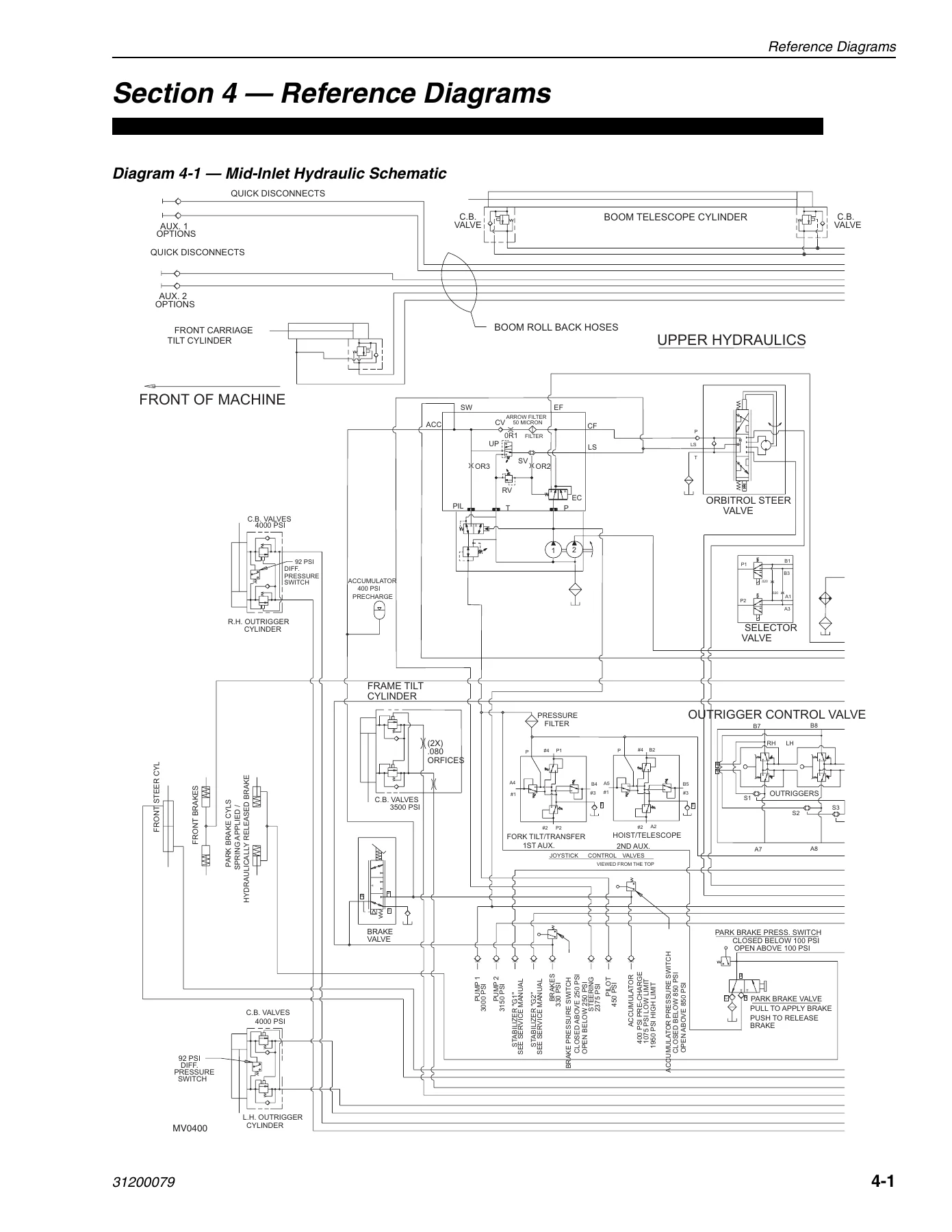
- Section 4 — Reference Diagrams
- Section 5 — Supply, Pressure, and Return Hydraulics
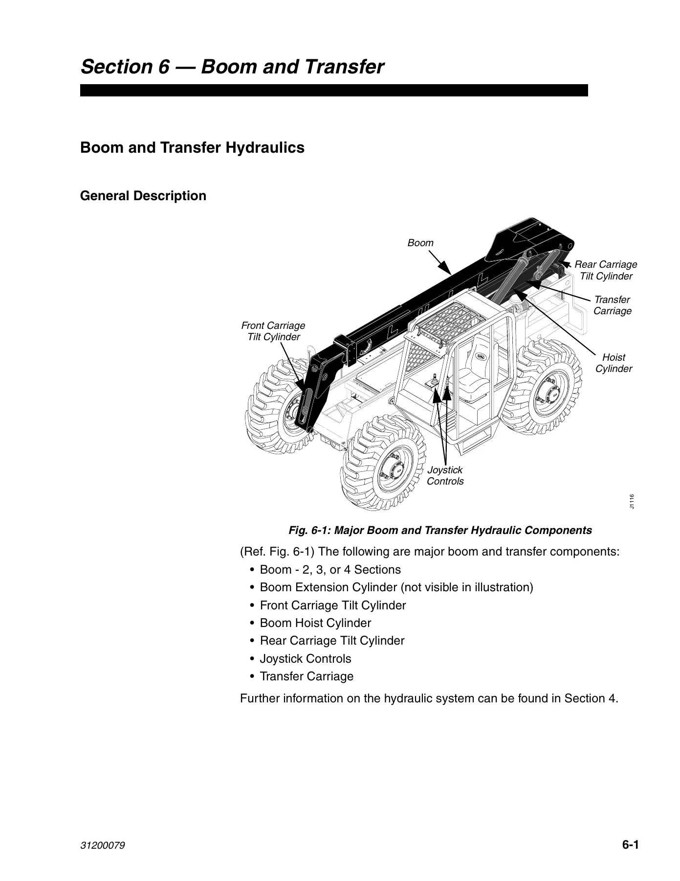
- Section 6 — Boom and Transfer Hydraulics
- Section 7 — Frame Tilt and Oscillation
- Section 8 — Transmission
- Section 9 — Axles and Brakes
- Section 10 — Outriggers
Safety, Identification, Specifications and General Maintenance (Sections 1–3)
Section 1 lays out the entire safety framework for the 1044C-54 Series II: the Caution, Warning and Danger signal-word hierarchy, the ASME/ANSI B56.6 rough terrain forklift truck standard, mounting and dismounting rules, and dedicated safety coverage for fuel, engine coolant, hydraulic systems, electrical systems, tires and wheels, and the ROPS/FOPS structure. It also lists every decal and placard with its location — attachment capacity plate, boom extension indicator, boom movement control, cab transfer extension, California Proposition 65 warning, low brake pressure, outrigger caution, parking brake, pressure test ports, tire ballast and more. Section 2 gives the serial number locations (machine plate on the frame behind the right front tire, John Deere engine plate on the left side of the engine near the starter and fuel pump, front and rear axle plate locations, attachment plate) and the identification and specification tables for the 1044C-54. Section 3 is the maintenance backbone: fluid and lubricant specifications, John Deere engine oil grades and temperature ranges, ZF transmission oil specifications, diesel fuel requirements (1D and 2D), lithium-base grease guidance, exterior and cab cleaning, long-term storage preparation and return-to-service steps, torque tables for standard and metric bolts, capscrews and nuts, hydraulic fitting torque tables for JIC, SAE, adjustable and non-adjustable O-ring fittings and O-ring plugs, pipe thread fitting turns, jump starting procedures and full inch/fraction/metric and miscellaneous conversion charts.
Reference Diagrams (Section 4)
A dedicated diagram section: the complete mid-inlet hydraulic schematic, the control valve diagram showing every spool section, and the full electrical schematic. These pages are the circuit-tracing reference for diagnosing hydraulic and electrical faults on the mid-inlet machine.
Supply, Pressure and Return Hydraulics (Section 5)
The full upstream hydraulic story for the JLG Lull 1044C-54 Series II: hydraulic reservoir and sight gauge, suction strainer, return filter with pressure-gauge condition check, reservoir breather, hydraulic pressure filter, and the two-section Vickers gear pump (G2020, 18 GPM cover-end and 26 GPM shaft-end at 2500 RPM) with removal, installation, internal inspection and a pump-flow-rate test procedure. Also covers the mid-inlet control valve (described in 6-spool, 7-spool with unloader, 8-spool with outriggers and 9-spool with 2nd auxiliary configurations), the rear axle stabilizer control valve with its full port and marking chart, the boom extend lockout valve, the roll-back hose tray and the eight hydraulic diagnostic ports (Pump 1, Pump 2, Rear Osc. Lock G1/G2, Brakes, Steering, Pilot and Accumulator) with their pressure limits.
Boom and Transfer Hydraulics (Section 6)
The largest chapter of the manual. Joystick controls with full disassembly and pilot-pressure adjustment (510 ±25 psi at idle). Hydraulic cylinder description, condition checking and internal-leakage testing. Boom hoist cylinder, front and rear carriage tilt cylinders with exploded views and rod-nut torque values. Selector valve for mid-inlet machines, boom slide pads (inspection, shimming, surface finish repair), the quick attach system (disconnect/connect procedure), boom angle inclinometer, and the complete 4-section boom: shimming procedure with the exact gap tolerances, deflection inspection limits, boom removal and installation, full boom disassembly and assembly with chain routing, chain tension check (1.5″–2.5″ sag), boom hose replacement, the 4-section extension cylinder (650 lb, 3000 psi, 149-3/4″ retracted / 280-3/4″ extended) with overhaul, boom extension proximity switch adjustment (0.19″–0.25″ gap), and the transfer carriage with front and rear rollers, bushings, spacer washers and scraper plate replacement (1/16″ roller-to-rail gap).
Frame Tilt and Oscillation (Section 7)
Frame tilt system with counterbalance valve cartridges, the multi-spool frame tilt control valve with its safety lock ring, the frame tilt cylinder with 10° side-to-side tilt, and the frame level indicator adjustment. The rear oscillation lock system gets full theory-of-operation coverage including four circuit-operation diagrams (below 40°, above 40°, above 20° below 40°, and with service brake applied) plus a Rear Oscillation Lock Circuit Test Matrix. Rear oscillation lock cylinder with removal, installation and overhaul. Oscillation control block with full component breakdown including pressure reducing cartridge, check valve cartridges, pilot pistons, solenoid valve and orifice plugs. Boom elevation proximity switch removal, installation and 0.19″–0.25″ gap adjustment.
Transmission (Section 8)
The ZF 4WG-98TC four-speed powershift transmission. Transmission description, torque converter operation, general and performance specifications (3.5, 6, 15.2 and 22 mph travel speeds), 19-quart fluid capacity, maintenance schedule (10-hour oil level check, 50-hour filter, 1000-hour oil and filter), transmission removal and installation procedures with all mount hardware torque values, transmission shift logic with the full K11–K17 relay and D1–D9 diode circuit schematic, and a detailed troubleshooting chart covering engagement faults, low clutch pressure, overheating, noise and leaks. External service references are given for the ZF 4WG-98TC Transmission Repair Manual (P/N 8990455) and Technical Data and Maintenance Manual (P/N 8990449).
Axles and Brakes (Section 9)
Front axle (ZF MS-T-3060, with parking brake mechanism and limited-slip) and rear axle (ZF MS-T-3055). Axle maintenance, inspection, internal service guidance, removal and installation procedures with wheel and tire handling. Drive shafts with inspection and service of cross-and-bearing assemblies, transmission-to-axle drive shaft removal and installation, drive shaft disassembly and assembly with the yoke-alignment procedure. Service brake pressure switch replacement. Accumulator — 3000 psi piston type, 116 cu in oil volume, 126 cu in gas volume, 4-inch bore — with pre-charging procedure, pre-charge check (375–425 psi nitrogen) and recharge pressure check (950–1200 psi). Towing a disabled machine with the manual park-brake release and reset procedures.
Outriggers (Section 10)
Outrigger assemblies with full removal and installation procedures including shaft, shim and clamp-plate details (torque to 320 ft-lbs). Outrigger cylinders with 15.63″ stroke, 3000 psi operating pressure, counterbalance valve cartridges, bushing replacement and rod-nut assembly. Differential pressure switch (cartridge-style, 6000 psi max, closes at 92 psi). Boom extension proximity switch removal, installation and gap adjustment. Outrigger control valves with tie-rod assembly and hydraulic hose torque values.
What This Service Manual Enables You to Do
With the 1044C-54 Series II Service Manual on the bench, every job on the machine is documented with the exact procedure and the exact value. Trace a hydraulic fault using the mid-inlet schematic and the eight diagnostic ports. Set boom chain tension to the specified sag. Shim boom slide pads to the correct gap and torque every slide-pad capscrew to 180 in-lbs. Overhaul the 4-section extension cylinder, torque the rod nut to 1460 ft-lbs and secure it with the setscrews. Repack the transmission relay and diode logic — and diagnose why the transmission won’t shift. Adjust the rear oscillation lock proximity switch to the 0.19″–0.25″ gap, or work through the full Rear Oscillation Lock Circuit Test Matrix when the lock light behaves unexpectedly. Pre-charge the brake accumulator to 375–425 psi and verify recharge pressure at 950–1200 psi. Everything is here in one 382-page PDF: correct fluid and lubricant choices, torque tables for metric and standard hardware, hydraulic fitting torque tables, capacities, pressures and step-by-step removal and installation procedures with exploded views.
Getting the procedure and the torque values right on a 32,000 lb rough terrain forklift is not optional. A wrong chain adjustment, a mis-shimmed boom, or a transmission repaired without the correct shift-logic reference can cause a failure that takes the machine off the job for days. This manual removes the guesswork — the values are the manufacturer’s, and the procedures are the ones the machine was designed around.
IMAGES PREVIEW
Delivery is instant. This is a digital PDF download — no shipping, no waiting. The file works on any laptop, tablet or phone and every page is printable, so you can keep a clean reference on the bench or a printed copy in the shop binder. Order today, download immediately after checkout, and start the job with the manual open.
Reviews
There are no reviews yet.