JLG T350 Service & Maintenance Manual (3121198) – PDF DOWNLOAD
TABLE OF CONTENTS:
JLG T350 Service & Maintenance Manual (3121198) – PDF DOWNLOAD
Section A. Introduction - Maintenance Safety Precautions............................................................................................................................................................................................................................. 3
A General........................................................................................................................................................................................................................................................................ 3
B Hydraulic System Safety........................................................................................................................................................................................................................................................ 3
C Maintenance.................................................................................................................................................................................................................................................................... 3
REVISON LOG.......................................................................................................................................................................................................................................................................... 4
Original Issue A - January 15, 2005.............................................................................................................................................................................................................................................. 4
Revised B - July 15, 2005........................................................................................................................................................................................................................................................ 4
Revised C - August 26, 2005...................................................................................................................................................................................................................................................... 4
Revised D - December 12, 2005.................................................................................................................................................................................................................................................... 4
Revised E - February 24, 2006.................................................................................................................................................................................................................................................... 4
Revised F - May 1, 2007.......................................................................................................................................................................................................................................................... 4
Revised G - September 28, 2011................................................................................................................................................................................................................................................... 4
Revised H - January 9, 2013...................................................................................................................................................................................................................................................... 4
Revised I - July XX, 2018........................................................................................................................................................................................................................................................ 4
Section 1. Specifications............................................................................................................................................................................................................................................................ 17
1.1 Operating Specifications..................................................................................................................................................................................................................................................... 17
1.2 Dimensional Data............................................................................................................................................................................................................................................................. 17
1.3 Capacities................................................................................................................................................................................................................................................................... 17
Fuel Tank.................................................................................................................................................................................................................................................................... 17
1.525 Gallon (5.77 Liters)................................................................................................................................................................................................................................................... 17
Hydraulic Tank Filling Volume Usable Volume.................................................................................................................................................................................................................................. 17
4.4 Gallon (16.65 Liters) 4.0 Gallon (15.1 Liters)........................................................................................................................................................................................................................... 17
1.16 qt. (1.0 Liter)......................................................................................................................................................................................................................................................... 17
1.4 Electric Power Unit.......................................................................................................................................................................................................................................................... 18
Power........................................................................................................................................................................................................................................................................ 18
3.0 kW....................................................................................................................................................................................................................................................................... 18
3.0 kW....................................................................................................................................................................................................................................................................... 18
3.0 kW....................................................................................................................................................................................................................................................................... 18
Voltage...................................................................................................................................................................................................................................................................... 18
24 VDC....................................................................................................................................................................................................................................................................... 18
24 VDC....................................................................................................................................................................................................................................................................... 18
24 VDC....................................................................................................................................................................................................................................................................... 18
Amperage..................................................................................................................................................................................................................................................................... 18
90........................................................................................................................................................................................................................................................................... 18
140.......................................................................................................................................................................................................................................................................... 18
230.......................................................................................................................................................................................................................................................................... 18
Speed........................................................................................................................................................................................................................................................................ 18
4000 rpm..................................................................................................................................................................................................................................................................... 18
3600 rpm..................................................................................................................................................................................................................................................................... 18
2900 rpm..................................................................................................................................................................................................................................................................... 18
Short Term Operation......................................................................................................................................................................................................................................................... 18
9 minutes.................................................................................................................................................................................................................................................................... 18
6 minutes.................................................................................................................................................................................................................................................................... 18
2 minutes.................................................................................................................................................................................................................................................................... 18
Intermittent Operation....................................................................................................................................................................................................................................................... 18
28%.......................................................................................................................................................................................................................................................................... 18
19%.......................................................................................................................................................................................................................................................................... 18
10%.......................................................................................................................................................................................................................................................................... 18
Flow Rate.................................................................................................................................................................................................................................................................... 18
3.0 gpm (11.3 lpm)........................................................................................................................................................................................................................................................... 18
2.7 gpm (10.2 lpm)........................................................................................................................................................................................................................................................... 18
2.2 gpm (8.3 lpm)............................................................................................................................................................................................................................................................ 18
Displacement................................................................................................................................................................................................................................................................. 18
0.192 cu.in. (3.15 cc)....................................................................................................................................................................................................................................................... 18
1.5 Tires........................................................................................................................................................................................................................................................................ 18
36 lbs. (16 kg).............................................................................................................................................................................................................................................................. 18
50 psi (350 kpa)............................................................................................................................................................................................................................................................. 18
90-120 ft. lbs. (122-164 Nm)................................................................................................................................................................................................................................................. 18
66 ft. lbs. (90 Nm).......................................................................................................................................................................................................................................................... 18
1.6 Engine....................................................................................................................................................................................................................................................................... 18
4-stroke, overhead valve, single cylinder.................................................................................................................................................................................................................................... 18
16.5 cu.in. (270 cm³)........................................................................................................................................................................................................................................................ 18
3.0 x 2.3 in. (77 x 58 mm)................................................................................................................................................................................................................................................... 18
8.4 hp (6.3 kW) at 3,600 rpm................................................................................................................................................................................................................................................. 18
14.1 ft.lbs. (19.1 Nm) at 2,500 rpm.......................................................................................................................................................................................................................................... 18
3.8 lb/hr (2.4 L/hr) at3600rpm............................................................................................................................................................................................................................................... 18
Unleaded gasoline with a pump octane......................................................................................................................................................................................................................................... 18
rating of 86 or higher....................................................................................................................................................................................................................................................... 18
NGK: BPR6ES.................................................................................................................................................................................................................................................................. 18
DENSO: W20EPR-U.............................................................................................................................................................................................................................................................. 18
0.028 - 0.031 in. (0.70 - 0.80 mm)........................................................................................................................................................................................................................................... 18
1.7 Battery...................................................................................................................................................................................................................................................................... 18
1.8 Batteries (Electric Machines)................................................................................................................................................................................................................................................ 18
Prior to 0030001804.......................................................................................................................................................................................................................................................... 18
0030001804 to Present........................................................................................................................................................................................................................................................ 18
Type......................................................................................................................................................................................................................................................................... 18
GC-110VNL.................................................................................................................................................................................................................................................................... 18
EVGC6A-A..................................................................................................................................................................................................................................................................... 18
Voltage...................................................................................................................................................................................................................................................................... 18
6-V Deep Cycle............................................................................................................................................................................................................................................................... 18
6-Volt....................................................................................................................................................................................................................................................................... 18
Amp Hour Rating.............................................................................................................................................................................................................................................................. 18
225Ah @ 20hr................................................................................................................................................................................................................................................................. 18
213Ah @ 20hr................................................................................................................................................................................................................................................................. 18
Reserve Capacity @ 75 Amps................................................................................................................................................................................................................................................... 18
447 Minutes.................................................................................................................................................................................................................................................................. 18
492 Minutes.................................................................................................................................................................................................................................................................. 18
AT -40° F (-40° C) Open Circuit Voltage...................................................................................................................................................................................................................................... 18
Greater or Equal to 6 Volts.................................................................................................................................................................................................................................................. 18
Life Cycle Rating............................................................................................................................................................................................................................................................ 18
600 Cycles................................................................................................................................................................................................................................................................... 18
Internal Resistance.......................................................................................................................................................................................................................................................... 18
No more than 2.5 mOhms @ 70° F (21° C) / 4.0................................................................................................................................................................................................................................. 18
m Ohms @ 0° F (-18°C)........................................................................................................................................................................................................................................................ 18
Battery Weight............................................................................................................................................................................................................................................................... 18
(minimum allowable).......................................................................................................................................................................................................................................................... 18
60 lbs.(27.12 kg)............................................................................................................................................................................................................................................................ 18
66 lbs.(30 kg)............................................................................................................................................................................................................................................................... 18
1.9 Lubrication.................................................................................................................................................................................................................................................................. 19
Hydraulic Oil................................................................................................................................................................................................................................................................ 19
1.10 Component Weights........................................................................................................................................................................................................................................................... 19
592.......................................................................................................................................................................................................................................................................... 19
269.......................................................................................................................................................................................................................................................................... 19
127.......................................................................................................................................................................................................................................................................... 19
58........................................................................................................................................................................................................................................................................... 19
1144......................................................................................................................................................................................................................................................................... 19
520.......................................................................................................................................................................................................................................................................... 19
983.......................................................................................................................................................................................................................................................................... 19
284.......................................................................................................................................................................................................................................................................... 19
113.......................................................................................................................................................................................................................................................................... 19
51........................................................................................................................................................................................................................................................................... 19
57........................................................................................................................................................................................................................................................................... 19
26........................................................................................................................................................................................................................................................................... 19
64........................................................................................................................................................................................................................................................................... 19
29........................................................................................................................................................................................................................................................................... 19
140.......................................................................................................................................................................................................................................................................... 19
64........................................................................................................................................................................................................................................................................... 19
137.......................................................................................................................................................................................................................................................................... 19
62........................................................................................................................................................................................................................................................................... 19
83........................................................................................................................................................................................................................................................................... 19
38........................................................................................................................................................................................................................................................................... 19
1.11 Pressure Settings........................................................................................................................................................................................................................................................... 19
Cold temperatures have a significant impact on pressure readings. JLG Industries Inc. recommends operating the machine until the hydraulic system has warmed to normal operating temperatures prior to checking pressures. JLG Industries Inc. also recomm................... 19
1.12 Maintenance & Lubrication................................................................................................................................................................................................................................................... 21
1. Wheel Bearings............................................................................................................................................................................................................................................................ 21
2. Hydraulic Oil............................................................................................................................................................................................................................................................. 21
3. Hydraulic Filter & Breather............................................................................................................................................................................................................................................... 21
4. Swing Bearing............................................................................................................................................................................................................................................................. 22
5. Swing Bearing Teeth....................................................................................................................................................................................................................................................... 22
6. Swing Drive............................................................................................................................................................................................................................................................... 22
7. Engine.................................................................................................................................................................................................................................................................... 22
8. Fuel Tank................................................................................................................................................................................................................................................................. 22
a. Engine (Prior to SN 0030004208)....................................................................................................................................................................................................................................... 22
b. Engine (SN 0030004208 to Present)..................................................................................................................................................................................................................................... 22
9. Trailer Jack.............................................................................................................................................................................................................................................................. 23
10. Surge Brake.............................................................................................................................................................................................................................................................. 23
11. Coupler & Hitch Ball..................................................................................................................................................................................................................................................... 23
12. Jockey Wheel Bearing (Drive and Set Option Only)......................................................................................................................................................................................................................... 23
Section 2. General................................................................................................................................................................................................................................................................... 29
2.1 Machine Preparation, Inspection, and Maintenance............................................................................................................................................................................................................................. 29
General...................................................................................................................................................................................................................................................................... 29
Preparation, Inspection, and Maintenance..................................................................................................................................................................................................................................... 29
Pre-Start Inspection......................................................................................................................................................................................................................................................... 29
Pre-Delivery Inspection and Frequent Inspection.............................................................................................................................................................................................................................. 29
Annual Machine Inspection.................................................................................................................................................................................................................................................... 29
Preventative Maintenance..................................................................................................................................................................................................................................................... 29
2.2 Service and Guidelines....................................................................................................................................................................................................................................................... 30
General...................................................................................................................................................................................................................................................................... 30
The following information is provided to assist you in the use and application of servicing and maintenance procedures contained in this book............................................................................................................................ 30
Safety and Workmanship....................................................................................................................................................................................................................................................... 30
Your safety, and that of others, is the first consideration when engaging in the maintenance of equipment. Always be conscious of weight. Never attempt to move heavy parts without the aid of a mechanical device. Do not allow heavy objects to rest in ............... 30
Cleanliness.................................................................................................................................................................................................................................................................. 30
1. The most important single item in preserving the long service life of a machine is to keep dirt and foreign materials out of the vital components. Precautions have been taken to safeguard against this. Shields, covers, seals, and filters are provi............... 30
2. At any time when air, fuel, or oil lines are disconnected, clear adjacent areas as well as the openings and fittings themselves. As soon as a line or component is disconnected, cap or cover all openings to prevent entry of foreign matter......................... 30
3. Clean and inspect all parts during servicing or maintenance, and assure that all passages and openings are unobstructed. Cover all parts to keep them clean. Be sure all parts are clean before they are installed. New parts should remain in their co............... 30
Components Removal and Installation.......................................................................................................................................................................................................................................... 30
1. Use adjustable lifting devices, whenever possible, if mechanical assistance is required. All slings (chains, cables, etc.) should be parallel to each other and as near perpendicular as possible to top of part being lifted......................................... 30
2. Should it be necessary to remove a component on an angle, keep in mind that the capacity of an eyebolt or similar bracket lessens, as the angle between the supporting structure and the component becomes less than 90 degrees....................................... 30
3. If a part resists removal, check to see whether all nuts, bolts, cables, brackets, wiring, etc., have been removed and that no adjacent parts are interfering......................................................................................................... 30
Component Disassembly and Reassembly......................................................................................................................................................................................................................................... 31
When disassembling or reassembling a component, complete the procedural steps in sequence. Do not partially disassemble or assemble one part, then start on another. Always recheck your work to assure that nothing has been overlooked. Do not make any ............... 31
Pressure-Fit Parts........................................................................................................................................................................................................................................................... 31
When assembling pressure-fit parts, use an anti-seize or molybdenum disulfide base compound to lubricate the mating surface.............................................................................................................................................. 31
Bearings..................................................................................................................................................................................................................................................................... 31
1. When a bearing is removed, cover it to keep out dirt and abrasives. Clean bearings in nonflammable cleaning solvent and allow to drip dry. Compressed air can be used but do not spin the bearing..................................................................... 31
2. Discard bearings if the races and balls (or rollers) are pitted, scored, or burned.................................................................................................................................................................................... 31
3. If bearing is found to be serviceable, apply a light coat of oil and wrap it in clean (waxed) paper. Do not unwrap reusable or new bearings until they are ready to install........................................................................................... 31
4. Lubricate new or used serviceable bearings before installation. When pressing a bearing into a retainer or bore, apply pressure to the outer race. If the bearing is to be installed on a shaft, apply pressure to the inner race..................................... 31
Gaskets...................................................................................................................................................................................................................................................................... 31
Bolt Usage and Torque Application............................................................................................................................................................................................................................................ 31
1. Use bolts of proper length. A bolt which is too long will bottom before the head is tight against its related part. If a bolt is too short, there will not be enough thread area to engage and hold the part properly. When replacing bolts, use only t............... 31
2. Unless specific torque requirements are given within the text, standard torque values should be used on heat- treated bolts, studs, and steel nuts, in accordance with recommended shop practices. (See Torque Chart Section 1.)...................................... 31
Hydraulic Lines and Electrical Wiring........................................................................................................................................................................................................................................ 31
Hydraulic System............................................................................................................................................................................................................................................................. 31
1. Keep the system clean. If evidence of metal or rubber particles are found in the hydraulic system, drain and flush the entire system.................................................................................................................................. 31
2. Disassemble and reassemble parts on clean work surface. Clean all metal parts with non-flammable cleaning solvent. Lubricate components, as required, to aid assembly................................................................................................. 31
Lubrication.................................................................................................................................................................................................................................................................. 32
Battery...................................................................................................................................................................................................................................................................... 32
Lubrication and Servicing.................................................................................................................................................................................................................................................... 32
2.3 Lubrication and Information.................................................................................................................................................................................................................................................. 32
Hydraulic System............................................................................................................................................................................................................................................................. 32
1. The primary enemy of a hydraulic system is contamination. Contaminants enter the system by various means, e.g., using inadequate hydraulic oil, allowing moisture, grease, filings, sealing components, sand, etc., to enter when performing maintenanc............... 32
2. The design and manufacturing tolerances of the component working parts are very close, therefore, even the smallest amount of dirt or foreign matter entering a system can cause wear or damage to the components and generally results in faulty opera............... 32
3. Cloudy oils indicate a high moisture content which permits organic growth, resulting in oxidation or corrosion. If this condition occurs, the system must be drained, flushed, and refilled with clean oil............................................................ 32
4. It is not advisable to mix oils of different brands or types, as they may not contain the same required additives or be of comparable viscosities. Good grade mineral oils, with viscosities suited to the ambient temperatures in which the machine is............... 32
Hydraulic Oil................................................................................................................................................................................................................................................................ 32
1. Refer to Section 1 for recommendations for viscosity ranges........................................................................................................................................................................................................... 32
2. JLG recommends Mobil 424 hydraulic oil, which has an SAE viscosity of 10W-30 and a viscosity index of 152............................................................................................................................................................. 32
Changing Hydraulic Oil....................................................................................................................................................................................................................................................... 32
1. Filter elements must be changed after the first 50 hours of operation and every 300 hours thereafter. If it is necessary to change the oil, use only those oils meeting or exceeding the specifications appearing in this manual. If unable to obtain t............... 32
2. Use every precaution to keep the hydraulic oil clean. If the oil must be poured from the original container into another, be sure to clean all possible contaminants from the service container. Always clean the mesh element of the filter and replac............... 32
3. While the unit is shut down, a good preventive maintenance measure is to make a thorough inspection of all hydraulic components, lines, fittings, etc., as well as a functional check of each system, before placing the machine back in service...................... 32
Lubrication Specifications................................................................................................................................................................................................................................................... 32
Specified lubricants, as recommended by the component manufacturers, are always the best choice, however, multi-purpose greases usually have the qualities which meet a variety of single purpose grease requirements. Should any question arise, regardin............... 32
2.4 Cylinder Drift............................................................................................................................................................................................................................................................... 33
Theory....................................................................................................................................................................................................................................................................... 33
Platform Drift............................................................................................................................................................................................................................................................... 33
Measure the drift of the platform to the ground. Lower booms (if equipped) slightly elevated, main boom fully extended with the rated load in the platform and power off. Maximum allowable drift is 2 inches (5 cm) in 10 minutes. If the machine does no............... 33
Cylinder Leakage Test........................................................................................................................................................................................................................................................ 33
Cylinder leakage is acceptable if it passes this test.................................................................................................................................................................................................................... 33
Cylinder Thermal Drift....................................................................................................................................................................................................................................................... 33
2.5 Pins and Composite Bearing Repair Guidelines................................................................................................................................................................................................................................. 34
1. Pinned joints should be disassembled and inspected if the following occurs:............................................................................................................................................................................................... 34
a. Excessive sloppiness in joints........................................................................................................................................................................................................................................ 34
b. Noise originating from the joint during operation..................................................................................................................................................................................................................... 34
2. Filament wound bearings should be replaced if any of the following is observed:........................................................................................................................................................................................... 34
a. Frayed or separated fibers on the liner surface....................................................................................................................................................................................................................... 34
b. Cracked or damaged liner backing...................................................................................................................................................................................................................................... 34
c. Bearings that have moved or spun in their housing..................................................................................................................................................................................................................... 34
d. Debris embedded in liner surface...................................................................................................................................................................................................................................... 34
3. Pins should be replaced if any of the following is observed (pin should be properly cleaned prior to inspection):......................................................................................................................................................... 34
a. Detectable wear in the bearing area................................................................................................................................................................................................................................... 34
b. Flaking, peeling, scoring, or scratches on the pin surface............................................................................................................................................................................................................ 34
c. Rusting of the pin in the bearing area................................................................................................................................................................................................................................ 34
4. Re-assembly of pinned joints using filament wound bearings................................................................................................................................................................................................................ 34
a. Blow out housing using compressed air to remove all dirt and debris. Bearings and bearing housings must be free of all contamination.................................................................................................................................. 34
b. Bearing/pins should be cleaned with a solvent to remove all grease and oil. Filament wound bearing are a dry joint and should not be lubricated unless otherwise instructed (i.e. sheave pins)........................................................................ 34
c. Pins should be inspected to ensure it is free of burrs, nicks, and scratches which would damage the bearing during installation and operation......................................................................................................................... 34
2.6 Welding on JLG Equipment..................................................................................................................................................................................................................................................... 34
Do the Following When Welding on JLG Equipment............................................................................................................................................................................................................................... 34
Do Not Do The Following When Welding On Jlg Equipment........................................................................................................................................................................................................................ 34
Section 3. Chassis & Turntable....................................................................................................................................................................................................................................................... 37
3.1 Breaking-in a New Trailer.................................................................................................................................................................................................................................................... 37
Retighten Lug Nuts at First 10, 25 & 50 Miles................................................................................................................................................................................................................................ 37
Adjust Brake Shoes at First 200 Miles........................................................................................................................................................................................................................................ 37
Synchronizing the Brake Systems.............................................................................................................................................................................................................................................. 37
3.2 Trailer inspection and Service Instructions.................................................................................................................................................................................................................................. 37
Fasteners and Frame Members.................................................................................................................................................................................................................................................. 37
Brake Shoes and Drums........................................................................................................................................................................................................................................................ 37
Manually Adjusting Brake Shoes............................................................................................................................................................................................................................................... 38
1. Jack up the trailer and secure it on adequate capacity jack stands.................................................................................................................................................................................................... 38
2. Be sure the wheel and brake drum rotate freely........................................................................................................................................................................................................................ 38
3. Remove the wheel and brake drum. Because of the special stub axle arrangement, adjustment cannot be made through the backing plate.................................................................................................................................... 38
4. With a screwdriver or standard adjusting tool, rotate the starwheel of the adjuster assembly to expand the brake shoes. Adjust the brake shoes out until the pressure of the linings against the drum produces a slight drag.......................................... 38
5. Remount the wheel and brake drum...................................................................................................................................................................................................................................... 38
6. Repeat the above procedure on all brakes.............................................................................................................................................................................................................................. 38
7. Lower the trailer to the ground....................................................................................................................................................................................................................................... 38
3.3 Electric Brakes.............................................................................................................................................................................................................................................................. 38
1. Primary Shoe.............................................................................................................................................................................................................................................................. 38
2. Retractor Spring.......................................................................................................................................................................................................................................................... 38
3. Secondary Shoe............................................................................................................................................................................................................................................................ 38
4. Hold Down Spring.......................................................................................................................................................................................................................................................... 38
5. Adjuster Assembly......................................................................................................................................................................................................................................................... 38
6. Adjuster Spring........................................................................................................................................................................................................................................................... 38
7. Magnet.................................................................................................................................................................................................................................................................... 38
8. Actuating Lever........................................................................................................................................................................................................................................................... 38
Brake Controller............................................................................................................................................................................................................................................................. 39
Brake Cleaning and Inspection................................................................................................................................................................................................................................................ 39
Shoes and Linings............................................................................................................................................................................................................................................................ 39
3.4 Hydraulic (Surge) Brakes..................................................................................................................................................................................................................................................... 39
1. Anchor Post............................................................................................................................................................................................................................................................... 39
2. Wheel Cylinder............................................................................................................................................................................................................................................................ 39
3. Hold Down Spring.......................................................................................................................................................................................................................................................... 39
4. Primary Shoe.............................................................................................................................................................................................................................................................. 39
5. Adjuster Assembly......................................................................................................................................................................................................................................................... 39
6. Adjuster Spring........................................................................................................................................................................................................................................................... 39
7. Secondary Shoe............................................................................................................................................................................................................................................................ 39
8. Backing Plate............................................................................................................................................................................................................................................................. 39
9. Retractor Spring.......................................................................................................................................................................................................................................................... 39
Self Adjusting Mechanism..................................................................................................................................................................................................................................................... 40
Parking Brake................................................................................................................................................................................................................................................................ 40
General Maintenance.......................................................................................................................................................................................................................................................... 40
DRUM BRAKE ADJUSTMENT.................................................................................................................................................................................................................................................... 40
1. Jack up trailer and secure on adequate capacity jack stands. check that the wheel and drum rotate freely.......................................................................................................................................................... 40
2. Remove the adjusting hole cover from the adjusting slot on the bottom of the brake backing plate.................................................................................................................................................................. 40
3. With a screwdriver or standard adjusting tool, rotate the starwheel of the adjuster assembly to expand the brake shoes. Adjust the brake shoes out until the pressure of the linings against the drum makes the wheel very difficult to turn...................... 40
4. Rotate the starwheel in the opposite direction until the wheel turns freely with a slight lining drag............................................................................................................................................................. 40
5. Replace the adjusting hole cove and lower the wheel to the ground................................................................................................................................................................................................. 40
6. Repeat the above procedure on all brakes. For best results, the brakes should all be set at the same clearance.................................................................................................................................................... 40
3.5 Mechanical Brake............................................................................................................................................................................................................................................................. 41
Brake Maintenance............................................................................................................................................................................................................................................................ 41
WHEEL BRAKES............................................................................................................................................................................................................................................................. 41
WHEEL MOUNTS............................................................................................................................................................................................................................................................. 41
replacing brake assembly complete........................................................................................................................................................................................................................................ 41
1. Follow steps 1 thru 7 of REPLACING BRAKE SHOES.................................................................................................................................................................................................................... 41
2. The brake assemblies are left and right specific, check the new assembly against the one fitted noting the position of the brake cable attachment. Remove the four bolts securing the backplate to the axle, remove the old assembly and install the ne........... 41
3. Continue with the procedure under REPLACING BRAKE SHOES, starting at step 18...................................................................................................................................................................................... 41
4. Follow the procedure under ADJUSTMENT............................................................................................................................................................................................................................. 41
replacing brake shoes.................................................................................................................................................................................................................................................... 41
1. Remove the wheels................................................................................................................................................................................................................................................. 41
2. Remove the hub cap................................................................................................................................................................................................................................................ 41
3. Slacken off the brake adjuster bolt until free. Some brake assemblies have a ratchet accessible through an opening in the backplate instead of the bolt........................................................................................................... 41
4. Remove the axle nut, this may be a castellated nut retained with a cotter pin or it may be a locknut.............................................................................................................................................................. 41
5. Remove the brake drum (hub puller may be required) taking care not to displace the bearings....................................................................................................................................................................... 41
6. Check the condition of the brake drum. Replace the brake drum if deep score marks are visible..................................................................................................................................................................... 41
1. Flanged Screw..................................................................................................................................................................................................................................................... 42
2. Flanged Screw..................................................................................................................................................................................................................................................... 42
3. Hub/Drum Assembly................................................................................................................................................................................................................................................. 42
4. Dust Cap.......................................................................................................................................................................................................................................................... 42
5. Flanged Nut....................................................................................................................................................................................................................................................... 42
6. Bearing........................................................................................................................................................................................................................................................... 42
7. Circle Clip....................................................................................................................................................................................................................................................... 42
8. Brake Shoe (Secondary)............................................................................................................................................................................................................................................ 42
9. Brake Shoe (Primary).............................................................................................................................................................................................................................................. 42
10. Tension Spring (Top)............................................................................................................................................................................................................................................. 42
11. Tension Spring (Bottom).......................................................................................................................................................................................................................................... 42
12. Tension Spring (Center).......................................................................................................................................................................................................................................... 42
13. Compression Spring Spreader...................................................................................................................................................................................................................................... 42
14. Adjusting Key.................................................................................................................................................................................................................................................... 42
15. Adjusting Bolt................................................................................................................................................................................................................................................... 42
16. Bolt............................................................................................................................................................................................................................................................. 42
17. Adjustment Hole Plug............................................................................................................................................................................................................................................. 42
18. Protective Shield................................................................................................................................................................................................................................................ 42
19. Drawbar Eye...................................................................................................................................................................................................................................................... 42
20. Protective Sleeve................................................................................................................................................................................................................................................ 42
21. Brake Cable...................................................................................................................................................................................................................................................... 42
7. Undo the locknut on the brake rod (front to rear) adjacent to the compensator. Slacken the second nut on the brake rod. Remove the half shell from the backplate and detach the brake cable................................................................... 43
8. Record the orientation of the brake shoes and springs on the backplate to ensure the new shoes and springs are replaced in the same position as the old....................................................................................................... 43
9. With care and using a suitable lever, lift sliding shoe carrier away from expander. Extract expander and retain............................................................................................................................................... 43
10. Remove brake shoe retaining spring taking care to retain the spring. Keep plate or pin at the rear of the backplate where installed.......................................................................................................................... 43
11. Lift off whole brake shoe assembly from backplate. Take care not to lose the two adjuster wedges............................................................................................................................................................. 43
12. Examine the components and springs, replace any damaged parts. Clean the mechanism and ensure that all parts are free to move. Do not lubricate.............................................................................................................. 43
13. Install the springs on the new brake shoes................................................................................................................................................................................................................... 43
14. Locate the shoes onto the backplate and position onto the adjuster wedges or cam block....................................................................................................................................................................... 43
15. Install the retaining springs................................................................................................................................................................................................................................ 43
16. Locate the expander into position on the fixed plate......................................................................................................................................................................................................... 43
17. With care, and using a suitable lever, position the expander between the shoes and release the lever......................................................................................................................................................... 43
18. Attach the brake cable and install the half shell. Always replace the brake cables if they show signs of wear, stiffness, damage, or fraying................................................................................................................. 43
19. Install the drum and bearing. Replace the split pin or lock nut depending upon which type of nut is used. If a cotter pin and castellated nut is used, the axle nut must be adjusted to allow the correct bearing clearance. If a locknut is used, it ....... 43
20. Install the hub cap.......................................................................................................................................................................................................................................... 43
21. Repeat the procedure on the other drum....................................................................................................................................................................................................................... 43
22. Install the tires and wheels................................................................................................................................................................................................................................. 43
23. Follow the procedure under ADJUSTMENT........................................................................................................................................................................................................................ 43
adjustment............................................................................................................................................................................................................................................................... 43
1. Turn each wheel in the direction of forward rotation. Turn the brake adjuster bolt clockwise until some resistance is felt as the brake shoes begin to grip the drum, then slowly turn the brake adjuster bolt counterclockwise until the wheel begins ........... 43
2. Turn the nut on the brake rod until the nut is in contact with the compensator.................................................................................................................................................................................... 43
3. Remove the handbrake locking bolt and operate the handbrake several times to ensure that the compensators are seated. Check the travel of individual brake cables. This should be 2-5 mm. If not, re-adjust the brake as appropriate.............................. 43
4. With the handbrake engaged, turn each wheel in the reverse direction. They should turn a little and then lock as the auto-reverse mechanism operates. As each wheel is turned there will be a rearward movement of the handbrake lever as the energy st........... 43
5. Check the compensators are at 90° to the brake rod with the brakes applied in forward and reverse. Misalignment can be corrected through adjustment of the cable locking nuts. This is particularly important if a new cable has been installed................... 43
6. Operate the handbrake and leave it on. Lower the trailer to the floor and recheck the torque of the wheel nuts.................................................................................................................................................... 43
7. Please note the brakes will not be 100% effective until the new linings have bedded in............................................................................................................................................................................ 43
8. The brake adjustment should be rechecked after a short journey.................................................................................................................................................................................................... 43
Adjustment and Readjustment of the Overrun Braking System.................................................................................................................................................................................................................... 44
adjusting the braking system............................................................................................................................................................................................................................................. 44
1. Place the trailer on jacks with the wheels off of the ground...................................................................................................................................................................................................... 44
2. Release the handbrake............................................................................................................................................................................................................................................. 44
3. Pull out the drawbar as far as it will go......................................................................................................................................................................................................................... 44
1. When carrying out adjustments, always start with the wheel brakes................................................................................................................................................................................................. 44
2. When carrying out adjustments, turn the wheel only in the direction of forward travel............................................................................................................................................................................. 44
3. Do not pre-tension the expanding locking mechanism in the brake. If necessary, loosen the brake linkage at the brake compensator.................................................................................................................................. 44
4. Check the expanding locking mechanism and control cable for ease of movement...................................................................................................................................................................................... 44
adjustment procedure..................................................................................................................................................................................................................................................... 44
1. Brake............................................................................................................................................................................................................................................................. 44
a. Loosen the linkage............................................................................................................................................................................................................................................ 44
b. Tighten the adjusting screw (12) (on the outside of the brake plate, opposite the cable entry[13]), turning clockwise until the wheel can only be turned with difficulty or not at all........................................................................ 44
c. Ease off the adjusting screw (12) in the counterclockwise direction (approximately. 1/2 turn) until the wheel turns freely. Slight rubbing noises, which do not effect the free turning of the wheel, are permitted........................................... 44
d. When the brake is correctly adjusted, the actuating travel of the control cable (11) will be 5-8 mm........................................................................................................................................................... 44
e. Repeat the procedure on the other wheel....................................................................................................................................................................................................................... 44
2. Brake Compensating System......................................................................................................................................................................................................................................... 45
a. Preadjust the length of the brake linkage (slight play permitted)............................................................................................................................................................................................. 45
b. Operate the handbrake lever (3) and check the position of the compensating balances (9 & 10). They should be at right angles to the direction of towing....................................................................................................... 45
c. If necessary, adjust the position of the balance (10) and control cables (11)................................................................................................................................................................................. 45
d. The compression spring may only be lightly pre-tensioned and must not become fully compressed when activated.................................................................................................................................................. 45
3. Brake Linkage..................................................................................................................................................................................................................................................... 45
a. Adjust the brake linkage so that it is free of play longitudinally, without initial tension (reversing lever free of play).................................................................................................................................... 45
b. Readjustment: Operate the handbrake lever powerfully several times in order to settle the braking system. Check the position of the brake compensating balances which should be at right angles to the direction of towing. Check the play in the linka....... 45
c. Final Check: Check fastenings for security (secure the hexagon locking nuts to the screw fastenings for the transmission system, control cables, brake compensators, turnbuckle, linkage, etc.) Check the compression spring for initial tension.............. 45
d. Test Run: If necessary, carry out 2-3 brake tests............................................................................................................................................................................................................. 45
e. Brake Test: Recheck the play in the brake linkage and if necessary, readjust the linkage for length free of play; during operating braking with empty trailer should be used maximally 1/2 of the overrun travel.............................................. 45
readjusting the braking system........................................................................................................................................................................................................................................... 45
1. Readjustment:..................................................................................................................................................................................................................................................... 45
a. Operate the handbrake lever powerfully several times in order to settle the braking system.................................................................................................................................................................... 45
b. Check the position of the brake compensating balances (which should be at right angles to the direction of towing)............................................................................................................................................ 45
c. Recheck the play in the linkage............................................................................................................................................................................................................................... 45
d. If necessary, adjust the linkage again so that it is free of play, but without the initial tension............................................................................................................................................................ 45
e. Check the positions of the handbrake lever and compression spring (only light initial tension)................................................................................................................................................................ 45
f. When checking the dead center of the lever, resistance starts 10-15 mm above dead centre...................................................................................................................................................................... 45
2. Final Check:...................................................................................................................................................................................................................................................... 45
a. Check the screw fastenings for the transmission system (control cables, brake compensators, linkage, etc.).................................................................................................................................................... 45
Troubleshooting.............................................................................................................................................................................................................................................................. 46
3.6 Hubs, Drums, Wheel Bearings.................................................................................................................................................................................................................................................. 51
Hub Removal.................................................................................................................................................................................................................................................................. 51
1. Elevate and support the machine....................................................................................................................................................................................................................................... 51
2. Using adequate support to the wheel, Remove the nut securing wheel to hub............................................................................................................................................................................................. 51
3. Remove the wheel...................................................................................................................................................................................................................................................... 51
4. Remove the grease cap by carefully prying progressively around the flange of the cap.................................................................................................................................................................................. 51
5. Remove the cotter pin from the spindle nut............................................................................................................................................................................................................................ 51
6. Unscrew the spindle nut (counterclockwise) and remove the spindle washer.............................................................................................................................................................................................. 51
7. Remove the hub from the spindle, being careful not to allow the outer bearing cone to fall out. The inner bearing cone will be retained by the seal................................................................................................................... 51
Brake Drum Inspection........................................................................................................................................................................................................................................................ 51
1. The drum surface (where the brake shoes make contact) should be inspected for excessive wear or heavy scoring. If worn more than 0.020 in. (0.50 mm) oversized, or the drum has worn out of round by more than 0.015 in. (0.38 mm), then the drum surfa............... 51
Bearing Inspection........................................................................................................................................................................................................................................................... 51
1. Place the hub on a flat work surface with the cup to be replaced on the bottom side................................................................................................................................................................................... 51
2. Using a brass drift punch, carefully tap around the small diameter end of the cup to drive out........................................................................................................................................................................ 51
3. After cleaning the hub bore area, replace the cup by tapping in with the brass drift punch. Be sure the cup is seated all the way up against the retaining shoulder in the hub........................................................................................ 51
Bearing Lubrication.......................................................................................................................................................................................................................................................... 52
1. Place a quantity of grease into the palm of your hand................................................................................................................................................................................................................. 52
2. Press a section of the widest end of the bearing into the outer edge of the grease pile closest to the thumb forcing grease into the interior of the bearing.......................................................................................................... 52
3. Repeat this while rotating the bearing from roller to roller.......................................................................................................................................................................................................... 52
4. Continue this process until the entire bearing is completely filled with grease....................................................................................................................................................................................... 52
5. Before installing, apply a light coat of grease on the bearing cup.................................................................................................................................................................................................... 52
Seal Inspection and Replacement.............................................................................................................................................................................................................................................. 52
1. Pry the seal out of the hub with a screwdriver. Never drive the seal out with the inner bearing as you may damage the bearing......................................................................................................................................... 52
2. Apply a sealant, such as PERMATEX, to the outside of the new seal..................................................................................................................................................................................................... 52
3. Tap the new seal into place using a clean wooden block................................................................................................................................................................................................................ 52
Bearing Adjustment........................................................................................................................................................................................................................................................... 52
1. Rotate the hub assembly slowly while tightening the spindle nut to approximately 50 ft.lbs. (68 Nm)................................................................................................................................................................... 52
2. Loosen the spindle nut to remove the torque. DO NOT ROTATE THE HUB.................................................................................................................................................................................................... 52
3. Finger tighten the spindle nut until just snug........................................................................................................................................................................................................................ 52
4. Back the spindle nut out slightly until the first castellation lines up with the cotter key hole and insert the cotter pin............................................................................................................................................ 52
5. Bend over the cotter pin legs to secure the nut....................................................................................................................................................................................................................... 52
1. Grease Seal........................................................................................................................................................................................................................................................... 53
2. Inner Bearing Cone.................................................................................................................................................................................................................................................... 53
3. Inner Bearing Cup..................................................................................................................................................................................................................................................... 53
4. Brake Assembly........................................................................................................................................................................................................................................................ 53
5. Hub Assembly.......................................................................................................................................................................................................................................................... 53
6. Wheel Stud............................................................................................................................................................................................................................................................ 53
7. Outer Bearing Cup..................................................................................................................................................................................................................................................... 53
8. Outer Bearing Cone.................................................................................................................................................................................................................................................... 53
9. Spindle Washer........................................................................................................................................................................................................................................................ 53
10. Spindle Nut.......................................................................................................................................................................................................................................................... 53
11. Cotter Pin........................................................................................................................................................................................................................................................... 53
12. Grease Cap........................................................................................................................................................................................................................................................... 53
13. Wheel Nut............................................................................................................................................................................................................................................................ 53
14. Hub.................................................................................................................................................................................................................................................................. 53
3.7 Tires & Wheels............................................................................................................................................................................................................................................................... 54
Tire Inflation............................................................................................................................................................................................................................................................... 54
Tire Wear.................................................................................................................................................................................................................................................................... 54
Center Wear.................................................................................................................................................................................................................................................................. 54
Over Inflation............................................................................................................................................................................................................................................................... 54
Adjust Pressure to value specified in Section 7.............................................................................................................................................................................................................................. 54
Edge Wear.................................................................................................................................................................................................................................................................... 54
Under Inflation.............................................................................................................................................................................................................................................................. 54
Adjust Pressure to value specified in Section 7.............................................................................................................................................................................................................................. 54
Cupping...................................................................................................................................................................................................................................................................... 54
Out of balance............................................................................................................................................................................................................................................................... 54
Check bearing adjustment and balance tires................................................................................................................................................................................................................................... 54
Flat Spots................................................................................................................................................................................................................................................................... 54
Wheel lockup and tire skidding............................................................................................................................................................................................................................................... 54
Avoid sudden stops when possible and adjust brakes........................................................................................................................................................................................................................... 54
Tire Replacement......................................................................................................................................................................................................................................................... 55
Unless specifically approved by JLG Industries Inc. do not replace a foam filled or ballast filled tire assembly with a pneumatic tire. When selecting and installing a replacement tire, ensure that all tires are inflated to the pressure recommended b........... 55
Wheel Replacement........................................................................................................................................................................................................................................................ 55
Wheel Installation....................................................................................................................................................................................................................................................... 55
1. Start all nuts by hand to prevent cross threading. DO NOT use a lubricant on threads or nuts...................................................................................................................................................................... 55
2. Tighten nuts in the following sequence:........................................................................................................................................................................................................................... 55
3. The tightening of the nuts should be done in stages. Following the recommended sequence, tighten nuts per wheel torque chart...................................................................................................................................... 55
1st Stage.................................................................................................................................................................................................................................................................... 55
2nd Stage.................................................................................................................................................................................................................................................................... 55
3rd Stage.................................................................................................................................................................................................................................................................... 55
20-25 (25-35)................................................................................................................................................................................................................................................................ 55
50-60 (70-80)................................................................................................................................................................................................................................................................ 55
90-120 (120-163)............................................................................................................................................................................................................................................................. 55
1st Stage.................................................................................................................................................................................................................................................................... 55
2nd Stage.................................................................................................................................................................................................................................................................... 55
3rd Stage.................................................................................................................................................................................................................................................................... 55
15 (20)...................................................................................................................................................................................................................................................................... 55
35 (50)...................................................................................................................................................................................................................................................................... 55
66 (90)...................................................................................................................................................................................................................................................................... 55
4. Wheel nuts should be torqued before first road use and after each wheel removal. Check and torque after the first 10 miles, 25 miles, and again at 50 miles. Check periodically thereafter............................................................................ 55
Lug Nuts (Bolts)......................................................................................................................................................................................................................................................... 55
3.8 Hydraulic Brake Coupler...................................................................................................................................................................................................................................................... 57
Troubleshooting.............................................................................................................................................................................................................................................................. 57
Bleeding the Brake System.................................................................................................................................................................................................................................................... 58
1. Remove the master cylinder filler cap and fill reservoir with DOT type 3 or 4 automotive brake fluid.................................................................................................................................................................. 58
2. Check all hydraulic line fittings and connections to make sure they are leak free..................................................................................................................................................................................... 58
3. At brake assembly, connect a bleeder hose to bleeder fitting on the wheel cylinder and submerge the free end in a container with brake fluid. DO NOT reuse brake fluid................................................................................................ 58
4. Loosen the bleeder fitting at the top of the brake assembly........................................................................................................................................................................................................... 58
5. Apply the actuator and tighten the bleeder fitting. Return the actuator to the forward position. Again, loosen the bleeder valve one turn and apply the actuator. Repeat this procedure until fluid expelled from the bleeder hose is free of air bubbl............... 58
6. When no air bubbles are visible, close the bleeder valve securely and remove the bleeder hose......................................................................................................................................................................... 58
7. Repeat steps 1 thru 6 for the remaining brake......................................................................................................................................................................................................................... 58
8. After bleeding has been completed, re-check fluid level in the master cylinder........................................................................................................................................................................................ 58
Towing....................................................................................................................................................................................................................................................................... 58
1. Position the actuator ball socket above the ball...................................................................................................................................................................................................................... 58
2. Hold the release handle in the open position. Release handle must be held in fully open position to remove from or place on ball...................................................................................................................................... 58
3. Lower trailer tongue until ball rests in ball socket.................................................................................................................................................................................................................. 59
4. Close the release handle. The release handle will close freely with finger pressure when the ball is properly inserted into the ball socket........................................................................................................................... 59
5. To make sure actuator is securely latched onto the ball, extend the trailer tongue jack to the ground and lift the tow vehicle and trailer combination 2 to 4 in. (50 to 100 cm). If the ball does not disengage, the actuator is securely attached................... 59
6. Insert a padlock or bolt through the lock hole for theft protection................................................................................................................................................................................................... 59
7. Connect the breakaway cable solidly to the bumper or frame of tow vehicle as near to the center as possible. Cable must hang clear of trailer tongue and long enough to permit short radius turns without pulling breakaway cable forward............................. 59
8. Make sure the breakaway cable (C) is in the released position with the indicator bead (B) touching or resting against the cable spring stop (A) as shown below........................................................................................................ 59
9. Cross safety chains under the tongue and securely attach to bumper or frame of tow vehicle............................................................................................................................................................................ 59
10. Retract the jack fully. Place the caster wheel in the stowed position................................................................................................................................................................................................ 59
11. Check for proper tow vehicle to trailer hook-up; the tow vehicle and trailer should be level with positive tongue load............................................................................................................................................... 59
12. The back-up lever must be positioned in the towing position (A) as shown below....................................................................................................................................................................................... 59
13. You are now ready to tow your vehicle................................................................................................................................................................................................................................ 59
Backing Up................................................................................................................................................................................................................................................................... 60
1. Follow steps 1 through 13 under Towing................................................................................................................................................................................................................................ 60
2. Before backing up a slope or through soft ground, pull the trailer forward slightly to assure the actuator socket is in the fully forward position.................................................................................................................... 60
3. Move the lever knob on the side of the actuator downward from the towing position (A) along the curved slot in the actuator frame to the back-up position (B). The slot has a notch at the bottom of its’ travel. Plush the lever knob down to engage................. 60
4. Back the trailer up................................................................................................................................................................................................................................................... 60
5. If the machine is to be uncoupled from the tow vehicle after backing with the lever knob engaged, block all wheels and pull forward slightly to take strain off of the actuator. Uncouple the actuator by lifting the release handle and raising the tr............... 60
Maintenance.................................................................................................................................................................................................................................................................. 60
1. Keep all links and pivots lubricated to prevent rusting and ensure ease of operation. Use SAE 30 oil, lubricate inside release handle and inside actuator body from the underside of the actuator..................................................................... 60
2. Check for leaks in the brake system. Periodic checks should be made on all hoses and fittings to guard against cuts and worn hoses which may cause failure (leaks, rupturing under pressure, and collapsing). Replace defective hoses................................. 60
3. Check brake fluid level in the master cylinder reservoir. Keep filled to within 1/2" (13 mm) from the top of the reservoir. Use only a DOT type 3 or 4 brake fluid.................................................................................................... 60
4. Flush the system yearly or when system is known to be contaminated.................................................................................................................................................................................................... 60
Extended Storage Instructions................................................................................................................................................................................................................................................ 60
1. Check brake system for proper fluid level in master cylinder, bleed all lines......................................................................................................................................................................................... 60
2. Lubricate all links and pivots to prevent any rusting................................................................................................................................................................................................................. 60
3. Remove wheel and drum assemblies and spray a good anti-corrosion compound under rubber boot on forward end of brake wheel cylinder. Avoid spraying drum and lining.................................................................................................... 60
4. Grease all bearings and reinstall wheel and drum assemblies........................................................................................................................................................................................................... 60
5. Make sure breakaway cable is fully released........................................................................................................................................................................................................................... 60
6. After extended storage, refer to Maintenance to insure trailer readiness for towing................................................................................................................................................................................... 60
7. Adjust drum brakes.................................................................................................................................................................................................................................................... 60
Proper Towing Checklist...................................................................................................................................................................................................................................................... 60
1. Inspect brake fittings for leaks...................................................................................................................................................................................................................................... 60
2. Adjust brakes every 2000 miles........................................................................................................................................................................................................................................ 60
3. Lubricate all mechanical moving parts................................................................................................................................................................................................................................. 60
4. Inspect the breakaway cable for any kinks............................................................................................................................................................................................................................. 60
5. Verify the correct size ball is used, without chips, dirt, or hairline cracks......................................................................................................................................................................................... 60
6. Securely attach safety chains to trailer and tow vehicle.............................................................................................................................................................................................................. 60
7. For proper braking, trailer should be level when attached to tow vehicle to produce a positive tongue load............................................................................................................................................................ 60
8. DOT 3 or DOT 4 brake fluid should be used in master cylinder and fill it from 1/2 full to 1/2" (13 mm) from top of cylinder reservoir................................................................................................................................. 60
1. Not Used.............................................................................................................................................................................................................................................................. 61
2. Not Used.............................................................................................................................................................................................................................................................. 61
3. Push Rod.............................................................................................................................................................................................................................................................. 61
4. Shock Absorber........................................................................................................................................................................................................................................................ 61
5. Release Handle........................................................................................................................................................................................................................................................ 61
6. Master Cylinder....................................................................................................................................................................................................................................................... 61
7. Gasket................................................................................................................................................................................................................................................................ 61
8. Boot.................................................................................................................................................................................................................................................................. 61
9. Stop.................................................................................................................................................................................................................................................................. 61
10. Not Used............................................................................................................................................................................................................................................................. 61
11. Locknut.............................................................................................................................................................................................................................................................. 61
12. Not Used............................................................................................................................................................................................................................................................. 61
13. Spring............................................................................................................................................................................................................................................................... 61
14. Bolt................................................................................................................................................................................................................................................................. 61
15. Cap.................................................................................................................................................................................................................................................................. 61
16. Lanyard.............................................................................................................................................................................................................................................................. 61
17. S-Hook............................................................................................................................................................................................................................................................... 61
18. Bolt................................................................................................................................................................................................................................................................. 61
19. Not Used............................................................................................................................................................................................................................................................. 61
20. Bolt................................................................................................................................................................................................................................................................. 61
21. Flatwasher........................................................................................................................................................................................................................................................... 61
22. Link................................................................................................................................................................................................................................................................. 61
23. Flatwasher........................................................................................................................................................................................................................................................... 61
24. Locknut.............................................................................................................................................................................................................................................................. 61
25. Block................................................................................................................................................................................................................................................................ 61
26. Bushing.............................................................................................................................................................................................................................................................. 61
27. Flatwasher........................................................................................................................................................................................................................................................... 61
28. Flatwasher........................................................................................................................................................................................................................................................... 61
29. Flatwasher........................................................................................................................................................................................................................................................... 61
30. Bracket.............................................................................................................................................................................................................................................................. 61
31. Shipping Plug........................................................................................................................................................................................................................................................ 61
32. Not Used............................................................................................................................................................................................................................................................. 61
33. Not Used............................................................................................................................................................................................................................................................. 61
34. Piston............................................................................................................................................................................................................................................................... 61
35. Housing.............................................................................................................................................................................................................................................................. 61
36. Hitch................................................................................................................................................................................................................................................................ 61
3.9 Combination Coupler.......................................................................................................................................................................................................................................................... 62
Bleeding the Brake System.................................................................................................................................................................................................................................................... 62
1. Remove the bolts and lockwashers that hold the lever guide and flat emergency lever spring............................................................................................................................................................................ 62
2. Remove the lever guide and emergency lever spring. Using short strokes, pull forward on the emergency lever, pumping the master cylinder until brake fluid within the master cylinder stops bubbling.................................................................. 62
3. Attach a bleeder hose to the bleeder valve on one of the wheels and submerge the other end of the hose into a transparent container partially filled with brake fluid................................................................................................. 62
4. Loosen the bleeder valve one turn, and while watching the hose in the container, use the emergency lever to pump the master cylinder as long as air bubbles continue to leave the hose. When bubbles stop, close the bleeder valve and repeat the proce............... 62
5. Once bleeding is completed, refill the master cylinder and attach the cap securely.................................................................................................................................................................................... 62
6. Replace the emergency lever spring, lever guide, lockwashers, and bolts............................................................................................................................................................................................... 62
7. Test the brakes by pulling the emergency lever forward until it locks into its second notch position (the lever should be approximately straight up).................................................................................................................. 62
8. Attempt to rotate the wheels in a forward direction. If any wheels rotate, the brakes must be adjusted. To adjust the brakes, release the emergency lever from the locked position, set each wheel’s brake adjustment up 2 or 3 notches............................... 62
9. Repeat the test procedure as necessary................................................................................................................................................................................................................................ 62
General Maintenance.......................................................................................................................................................................................................................................................... 62
1. Frequently check brake fluid level. Fluid must be approved, clean, and uncontaminated................................................................................................................................................................................. 62
2. Make sure actuator mounting bolts are secure.......................................................................................................................................................................................................................... 62
3. Inspect the actuator and replace any bent, worn, or damaged parts..................................................................................................................................................................................................... 62
4. Be constantly aware of the system’s braking quality, make periodic checks. Consult a certified brake specialist to make necessary adjustments or repairs.............................................................................................................. 62
Servicing the Emergency Lever................................................................................................................................................................................................................................................ 62
1. Remove the master cylinder and push rod assembly. Be careful not to get dirt into the master cylinder. A new master cylinder gasket should be used when reinstalling the master cylinder.............................................................................. 62
2. Remove the cable S-hook from the emergency lever, emergency lever guide and flat emergency lever spring, then pull the lever out of the actuator outer case through the cross-slot in the top......................................................................... 62
3. Install the new emergency lever through the cross-slot in top of the outer case. Attach a new emergency lever spring and emergency lever guide........................................................................................................................ 62
4. Insert the S-hook on the emergency cable into the hole in the emergency lever and squeeze shut........................................................................................................................................................................ 62
5. Add adequate brake fluid to the master cylinder and bleed the brake system............................................................................................................................................................................................ 62
1. Not Used.............................................................................................................................................................................................................................................................. 63
2. Not Used.............................................................................................................................................................................................................................................................. 63
3. Not Used.............................................................................................................................................................................................................................................................. 63
4. Pin................................................................................................................................................................................................................................................................... 63
5. Not Used.............................................................................................................................................................................................................................................................. 63
6. Damper Shock.......................................................................................................................................................................................................................................................... 63
7. Outer Case............................................................................................................................................................................................................................................................ 63
8. Lockwasher............................................................................................................................................................................................................................................................ 63
9. Cotter Pin............................................................................................................................................................................................................................................................ 63
10. Cable with Hooks..................................................................................................................................................................................................................................................... 63
11. Hook................................................................................................................................................................................................................................................................. 63
12. Emergency Lever Spring Plate......................................................................................................................................................................................................................................... 63
13. Bolt................................................................................................................................................................................................................................................................. 63
14. Bolt................................................................................................................................................................................................................................................................. 63
15. Lockwasher........................................................................................................................................................................................................................................................... 63
16. Lanyard.............................................................................................................................................................................................................................................................. 63
17. S-Hook............................................................................................................................................................................................................................................................... 63
18. Push Rod & Piston Assembly........................................................................................................................................................................................................................................... 63
19. Nut.................................................................................................................................................................................................................................................................. 63
20. Gasket............................................................................................................................................................................................................................................................... 63
21. Reservoir............................................................................................................................................................................................................................................................ 63
22. Fitting w/ Orifice................................................................................................................................................................................................................................................... 63
23. Emergency Lever Guide................................................................................................................................................................................................................................................ 63
24. Boot................................................................................................................................................................................................................................................................. 63
25. Pin.................................................................................................................................................................................................................................................................. 63
26. Upper Slider......................................................................................................................................................................................................................................................... 63
27. Lower Slider......................................................................................................................................................................................................................................................... 63
28. Side Spacer 55. Channel Centered Slider.............................................................................................................................................................................................................................. 63
3.10 Coupler Assembly (SN 0030002099 to Present)................................................................................................................................................................................................................................. 64
Engaging Manual Lockout Lever................................................................................................................................................................................................................................................ 64
Servicing the Breakaway Assembly............................................................................................................................................................................................................................................. 64
Actuator Maintenance......................................................................................................................................................................................................................................................... 66
1. Frequently check brake fluid level (fluid must be DOT3 or 4 approved, clean and uncontaminated)....................................................................................................................................................................... 66
2. Make sure mounting bolts are properly tightened 15 to 20 ft lbs (20 to 27 Nm) without deformation of coupler.......................................................................................................................................................... 66
3. Inspect entire actuator, replace any bent, worn or damaged parts immediately.......................................................................................................................................................................................... 66
4. Be constantly aware of systems braking quality, make periodic checks as described in the brakes owners manual. Consult certified brake specialist to make necessary adjustments or repairs. Failure to do so could result in loss of braking.......................... 66
5. Be sure hydraulic lines and fittings are tight to avoid fluid leaks................................................................................................................................................................................................... 66
Coupler Maintenance.......................................................................................................................................................................................................................................................... 66
1. Maintain a film of automotive grease in the ball pocket, ball clamp (front & back), ball clamp spring, where link pin enters housing, and where the housing contacts the bracket hardware............................................................................. 66
2. Maintain a film of oil on the pivot points and safety latch spring using SAE 30W motor oil............................................................................................................................................................................ 66
3. Keep the ball pocket and mechanism clean because dirt, paint, etc. can hinder proper operation. When parking or storing your trailer, keep the bracket and coupler off the ground so dirt and/or other foreign material will not build up in the couple............... 66
4. Grease pivot hinge with automotive grease............................................................................................................................................................................................................................. 66
3.11 Hitch Coupler & Axle (CE Only).............................................................................................................................................................................................................................................. 67
Ball Coupler................................................................................................................................................................................................................................................................. 67
UNCOUPLING............................................................................................................................................................................................................................................................... 67
COUPLING................................................................................................................................................................................................................................................................. 67
1. The ball on the towing vehicle is very worn down and the ball coupler cannot grip it properly. A new ball has a diameter of 50.0 mm. If the diameter is worn down to less than 49 mm, even if only in places, it is vital to replace the ball on the to........... 68
2. The ball coupler itself is very worn down and no longer grips the ball sufficiently. In this case, the ball coupler must be replaced at a qualified workshop...................................................................................................... 68
3. The closing mechanism in the ball coupler has been triggered, but there is no ball in the coupling. The ball coupler is only lying loose on the ball and is not firmly connected. The coupling will separate from the ball when the towing vehicle driv........... 68
PERMISSIBLE SUPPORT LOAD................................................................................................................................................................................................................................................. 68
POSITION OF THE COUPLING POINT ON THE TRAILER............................................................................................................................................................................................................................ 68
BALL COUPLER Maintenance................................................................................................................................................................................................................................................. 68
OVER-RUN HITCH Maintenance............................................................................................................................................................................................................................................... 68
1. Put the handbrake on while the trailer is uncoupled and push the trailer slowly backwards until the handbrake lever has reached the hindmost end position......................................................................................................... 68
2. Push the ball coupler/connecting rod into the over-run hitch. Depending on the over-run hitch, it will require a certain amount of force to push.................................................................................................................. 68
3. The connecting rod should then return automatically to zero position by means of the gas cushion in the hydraulic damper. If it takes longer than approximately 30 seconds to return, the over-run hitch must be checked at a qualified workshop.................. 68
Coupling Head Maintenance.................................................................................................................................................................................................................................................... 69
REPLACING................................................................................................................................................................................................................................................................ 69
1. Follow steps 1 thru 4 under Damper Maintenance - REMOVAL.......................................................................................................................................................................................................... 69
2. If you have been able to remove the coupling head/eye as instructed under Damper Maintenance - REMOVAL step 4, go to step 5 below, otherwise proceed with step 3.................................................................................................. 69
3. The damper will now be retained between the front coupling/eye bolt and the rear damper bracket. It is now necessary to remove the damper without destroying it. WARNING: Proceed with caution! The most efficient method is to remove the rear damper ........... 69
4. Place a lever against the rear damper in such a manner that once the mounting bracket bolts are removed the tension can be released slowly. Take the tension and remove the mounting bracket bolts, release the tension in the damper............................. 69
5. Inspect the shaft for damage, dress burrs, and clean any dirt as the new coupling will be a close fit on the shaft................................................................................................................................................ 69
6. If a new bellows is to be fitted cut the tie-wrap and discard the old one, fit the new and secure with a tie-strap................................................................................................................................................ 69
7. Trial fit the new coupling. It should slide into place without any undue force. DO NOT hammer the coupling into place, this can damage the coupling itself or the over- run mechanism. If it proves to be tight, remove it and thoroughly clean the sha........... 69
8. Fit the bolts, washers and secure with NEW locking nuts and torque to 85 ft. lbs. (115 Nm). DO NOT re-use the old nuts as this is safety critical. Fit the plastic nut covers. Where the damper has been removed ensure that the coupling head rear bol........... 69
9. If the damper has been released the rear mounting bracket will need to be re-fitted. This means that the damper needs to be compressed so the bolts can be installed. WARNING: Proceed with caution! Compress the damper with the lever and secure the ........... 69
10. Reinstall the bellows with the coupling/eye horizontal taking care not to tear or damage the material. If the replacement coupling/eye is a different part than the original:.................................................................................... 69
a. Always ensure the corresponding length bolts are used......................................................................................................................................................................................................... 69
b. Always ensure a compatible bellows is used.................................................................................................................................................................................................................... 69
c. Always ensure the hole sizes in the coupling and draw-bar tube match and the correct size bolts are used...................................................................................................................................................... 69
damper reaction test..................................................................................................................................................................................................................................................... 69
1. Pull the handbrake lever on as far as possible.................................................................................................................................................................................................................... 69
2. Push the ball coupling as far back into the overrunning hitch as it will go. This requires force to compress and should extend smoothly when released............................................................................................................. 69
3. If the draw tube is impossible to compress, compresses with just spring force and no damping resistance, or the extension is very rapid, the damper must be replaced by carefully following the replacement instructions above.................................... 69
Damper Maintenance........................................................................................................................................................................................................................................................... 70
REMOVAL.................................................................................................................................................................................................................................................................. 70
1. Pull back the bellows from the coupling to expose the two retaining bolts......................................................................................................................................................................................... 70
2. Undo the self locking nut from the rear bolt of the coupling as shown............................................................................................................................................................................................. 70
3. Remove the rear bolt; force may be required as the damper may still be preloaded. Raise the coupling operating handle in order to fully remove the bolt if necessary.............................................................................................. 70
4. When the rear bolt is removed the damper will move forward to rest upon the front bolt. In some instances a retaining pin is used; located between the bolt holes. This pin will hold the damper in its original position and will therefore need to be........... 70
a. Undo the self locking nut from the front bolt, extract the bolt and remove the head........................................................................................................................................................................... 70
b. Replace both bolts in the draw tube and finger tighten the bolts.............................................................................................................................................................................................. 70
c. Knock out the retaining pin and remove the rear bolt, this will allow the damper to move forward and contact the front bolt................................................................................................................................... 70
5. From underneath, through the bolt hole in the draw tube, drill a 3 mm hole into the damper body to a depth of 8 mm................................................................................................................................................ 70
6. The pressure in the damper should now have been discharged. Remove the self locking nut on the front bolt of the coupling head. Remove the bolt and the coupling head. If the bolt is difficult to remove, it indicates that there is still residual fo........... 70
7. Remove the rear damper bracket retaining bolts. Also remove the nuts and spring washer from the rear of the damper................................................................................................................................................ 70
8. The de-pressurized damper can now be removed by sliding the damper forward through the draw tube and be disposed off.............................................................................................................................................. 70
3.12 Trailer Jack................................................................................................................................................................................................................................................................ 72
Installation................................................................................................................................................................................................................................................................. 72
1. Place the jack against the trailer tongue and position the mounting straps on the opposite side of the tongue. Place the straps so the flat side is against the tongue................................................................................................ 72
2. Install the bolts through the bracket and straps. Position the jack so the top bolts rest directly on the top of the tongue and the bottom bolts are as close to the tongue as possible. The gap between the mounting bolts and the trailer tongue is n............... 72
3. Secure the bolts in place with the locknuts. Torque the nuts to 25 ft.lbs. (34 Nm).................................................................................................................................................................................... 72
4. Check for clearance of handle swing, trailer light cables, and coupler clearance...................................................................................................................................................................................... 72
Operation.................................................................................................................................................................................................................................................................... 72
Maintenance.................................................................................................................................................................................................................................................................. 72
Assembly..................................................................................................................................................................................................................................................................... 73
HANDLE................................................................................................................................................................................................................................................................... 73
1. Place one spacer over the bolt.................................................................................................................................................................................................................................... 73
2. Lightly grease the split tube spacer.............................................................................................................................................................................................................................. 73
3. Place the bolt and spacers through the roller. Insert the bolt through the handle................................................................................................................................................................................. 73
4. Install the locknut onto the bolt and tighten. Adjust the nut so the bolt no longer turns freely. A minimum of two full bolt threads must be visibly extended through the nut..................................................................................... 73
CASTER WHEEL............................................................................................................................................................................................................................................................. 73
1. Grease the outside of the wheel spacer using standard automotive grease and insert it into the wheel.............................................................................................................................................................. 73
2. Place the wheel and spacer into the yoke and align the holes in the wheel with the holes in the yoke.............................................................................................................................................................. 73
3. Insert the bolt through both sides of the yoke. Make sure the threads of the bolt are to the outside of the yoke when the yoke hangs down in the trailering position.............................................................................................. 73
4. Install the locknut and tighten until the yoke is just tight enough against the metal spacer to keep the spacer from rotating. Do not overtighten, this can cause the spacer to deform and bind the wheel. The wheel must spin freely............................. 73
3.13 Swing Motor (Prior to SN 003000641)......................................................................................................................................................................................................................................... 74
Removal...................................................................................................................................................................................................................................................................... 74
1. Remove the hardware securing the motor to the swing drive............................................................................................................................................................................................................. 74
2. Lift the motor up to gain access to the hydraulic lines and tag and disconnect the lines running to the motor. Cap or plug all openings............................................................................................................................... 74
Disassembly.................................................................................................................................................................................................................................................................. 74
1. Remove all shaft related components from the shaft (i.e. keys, wire rings, nuts). To aid in assembly of the motor, make a V shaped set of lines from the end cover to the housing using either paint or a marker...................................................... 74
2. With the shaft facing down, secure the motor in a vise by clamping onto the housing................................................................................................................................................................................... 74
3. Loosen and remove the bolts holding the motor assembly together....................................................................................................................................................................................................... 74
4. Remove the end cover.................................................................................................................................................................................................................................................. 74
5. Remove the body seal and discard the seal............................................................................................................................................................................................................................. 74
6. Remove the rotor assembly and wear plate. Remove the body seals from the rotor and housing and discard the seals...................................................................................................................................................... 74
7. Remove the drive link pin and drive link from the motor and lay aside................................................................................................................................................................................................. 74
8. Gently tap the shaft upward through the housing and remove through the rear of the housing. Turn the shaft over and remove the cooling plug........................................................................................................................... 74
9. Remove the housing from the vise and turn over. Pry the dust seal from the housing.................................................................................................................................................................................... 74
10. Push the seal carrier, thrust washer, and thrust bearing down and remove from the rear of the housing................................................................................................................................................................ 74
11. If a new seal carrier and thrust washer are included in the repair kit, the old items may be discarded. If not, carefully pry the shaft seal, teflon backup seal, and metal backup shim from the seal from the seal carrier and discard the metal back............... 74
12. Remove the wire ring, metal backup shim, and high pressure seal from the inner bore groove of the housing with a small screwdriver and discard them.................................................................................................................. 74
13. All parts should be cleaned in an oil based solvent and dried using compressed air. All new seals should be lightly coated in clean oil prior to installation........................................................................................................ 74
Assembly..................................................................................................................................................................................................................................................................... 75
1. Place the shaft on a clean flat surface with the output end facing up................................................................................................................................................................................................. 75
2. Place the thrust bearing, then thrust washer, on the shaft............................................................................................................................................................................................................ 75
3. Install the shaft seal down onto the shaft making sure the lip on the seal faces down. Refer to Figure 3-18., Seal Orientation........................................................................................................................................ 75
4. Install the teflon backup seal onto the shaft with the flat side up and the seal lip facing the shaft seal............................................................................................................................................................ 75
5. Place the metal backup shim onto the shaft and against the teflon backup seal......................................................................................................................................................................................... 75
6. Place the seal carrier onto the shaft (large end down) and carefully press the seal carrier down onto the seal assembly using an arbor press and sleeve to compress the seals into the carrier........................................................................ 75
7. Install the high pressure seal into the groove in the housing......................................................................................................................................................................................................... 75
8. Install the metal backup shim against the high pressure seal in the groove in the housing bore by squeezing the shim between the thumb and forefinger to bow shim (bow in the shim should be in the shape of a hill and not a valley for easier install............... 75
9. While maintaining the bow in the shim, start the shim into the groove and use a small screwdriver to push the shim into the groove. Install the wire ring into the groove making sure the ends are butted............................................................. 75
Shaft Timing Procedure....................................................................................................................................................................................................................................................... 75
1. Turn shaft over so the output end of the shaft faces down............................................................................................................................................................................................................. 75
2. Install the cooling plug into the shaft making sure the large OD end of the cooling plug faces up..................................................................................................................................................................... 75
3. Lower the drive link into the shaft making sure that the timing mark end of the drive link faces up and the timing mark on the end of the drive link is aligned with one of the through holes in the shaft............................................................ 75
4. When the splines contact each other, slowly rotate the drive link counterclockwise until the drive link splines engage with those on the shaft........................................................................................................................ 75
5. Turn the housing over so the pilot of the housing faces down and secure the housing in a vise......................................................................................................................................................................... 75
6. Without disturbing the seal carrier assembly or drive link, carefully lower the shaft assembly into the housing....................................................................................................................................................... 75
7. To seat the seal carrier against the wire ring, gently tap the drive link down until the end of the shaft is nearly flush with the rear surface of the housing........................................................................................................ 75
8. Place a body seal in the groove in the rear surface of the housing.................................................................................................................................................................................................... 75
9. Using alignment marks as a guide, place the wear plate on the housing making sure the notch in the wear plate is aligned with the port side of the housing as shown in Figure 3-19., Notch Alignment.................................................................. 75
10. Place a body seal in the grove in the face of the rotor.............................................................................................................................................................................................................. 76
11. Lower the rotor onto the drive link making sure the timing mark on the drive link is aligned with a peak on the rotor as shown in Figure 3-20., Timing Mark.......................................................................................................... 76
12. Once splines are engaged, rotate rotor so the notch on the rotor is aligned with the notch on the wear plate and the ports on the housing. Refer to Figure 3-19., Notch Alignment.................................................................................... 76
13. Insert the drive link pin into the end of the drive link making sure the concave end faces up........................................................................................................................................................................ 76
14. Place the remaining body seal in the groove in the end cover......................................................................................................................................................................................................... 76
15. Using alignment marks as a guide, place the end cover onto the motor making sure the end of the drive link pin is in the hole in the center of the end cover......................................................................................................... 76
16. Insert the four bolts and torque to an initial value of 10 ft.lbs. (13.5 Nm). Using a criss-cross pattern, apply a final torque of 50 ft.lbs. (68 Nm)................................................................................................................ 76
17. Remove the motor from the vise and place on a clean work surface with the shaft facing up. Making sure the lip seal faces up, place the dust seal over the shaft. Using a seal and hammer, carefully drive the dust seal into place.................................. 76
Installation................................................................................................................................................................................................................................................................. 76
1. Connect the two hydraulic lines to the motor as tagged during Removal................................................................................................................................................................................................. 76
2. Position the motor on the swing drive and secure in place with the retaining bolts. Torque the bolts to 95 ft.lbs. (130 Nm)........................................................................................................................................... 76
1. Dust Seal............................................................................................................................................................................................................................................................. 77
2. Retainer Ring......................................................................................................................................................................................................................................................... 77
3. Backup Shim........................................................................................................................................................................................................................................................... 77
4. Housing Seal.......................................................................................................................................................................................................................................................... 77
5. Body Seal............................................................................................................................................................................................................................................................. 77
6. Shaft Seal............................................................................................................................................................................................................................................................ 77
7. Thrust Washer......................................................................................................................................................................................................................................................... 77
8. Thrust Bearing........................................................................................................................................................................................................................................................ 77
9. Wear Plate............................................................................................................................................................................................................................................................ 77
10. End Cover............................................................................................................................................................................................................................................................ 77
11. Ball................................................................................................................................................................................................................................................................. 77
12. Cooling Plug......................................................................................................................................................................................................................................................... 77
13. Housing.............................................................................................................................................................................................................................................................. 77
14. Drive Link........................................................................................................................................................................................................................................................... 77
15. Rotor Set............................................................................................................................................................................................................................................................ 77
16. Drive Link Pin....................................................................................................................................................................................................................................................... 77
17. Bolt................................................................................................................................................................................................................................................................. 77
18. Shaft................................................................................................................................................................................................................................................................ 77
19. Key.................................................................................................................................................................................................................................................................. 77
3.14 Swing Motor (SN 0030001051 to Present)...................................................................................................................................................................................................................................... 78
Removal...................................................................................................................................................................................................................................................................... 78
1. Remove the two bolts securing the motor to the swing drive............................................................................................................................................................................................................ 78
2. Lift the motor up to gain access to the hydraulic lines and tag and disconnect the lines running to the motor. Cap or plug all openings............................................................................................................................... 78
Disassembly And Inspection................................................................................................................................................................................................................................................... 78
1. Place the Torqlink™ in a soft jawed vice, with coupling shaft (12) pointed down and the vise jaws clamping firmly on the sides of the housing (18) mounting flange or port bosses. Remove manifold port O-Rings (18A) if applicable................................... 78
2. Scribe an alignment mark down and across the Torqlink™ components from end cover (2) to housing (18) to facilitate reassembly orientation where required. Loosen two shuttle or relief valve plugs (21) for disassembly later if included in end cove................. 78
3. Remove the five, six, or seven special ring head bolts (1) using an appropriate 1/2 or 9/16 inch size socket. Inspect bolts for damaged threads, or sealing rings, under the bolt head. Replace damaged bolts......................................................... 78
4. Remove end cover assembly (2) and seal ring (4). Discard seal ring.................................................................................................................................................................................................... 80
5. If the end cover (2) is equipped with shuttle valve components, remove the two previously loosened plugs (21)......................................................................................................................................................... 80
6. Thoroughly wash end cover (2) in proper solvent and blow dry. Be sure the end cover valve apertures, including the internal orifice plug, are free of contamination. Inspect end cover for cracks and the bolt head recesses for good bolt head sealing............... 80
7. Remove commutator ring (6). Inspect commutator ring for cracks, or burrs.............................................................................................................................................................................................. 80
8. Remove commutator (5) and seal ring (3) Remove seal ring from commutator, using an air hose to blow air into ring groove until seal ring is lifted out and discard seal ring. Inspect commutator for cracks or burrs, wear, scoring, spalling or brinel............... 81
9. Remove manifold (7) and inspect for cracks surface scoring, brinelling or spalling. Replace manifold if any of these conditions exist. A polished pattern on the ground surface from commutator or rotor rotation is normal. Remove and discard the sea............... 81
10. Remove rotor set (8) and warplane (9), together to retain the rotor set in its assembled form, maintaining the same rotor vane (8C) to stator (8B) contact surfaces. The drive link (10) may come away from the coupling shaft (12) with the rotor set............... 81
11. Place rotor set (8) and wear plate (9) on a flat surface and center rotor (8A) in stator (8B) such that two rotor lobes (180 degrees apart) and a roller vane (8C) centerline are on the same stator centerline. Check the rotor lobe to roller vane c............... 82
12. Remove drive link (10) from coupling shaft (12) if it was not removed with rotor set and wear plate. Inspect drive link for cracks and worn or damaged splines. No perceptible lash (play) should be noted between mating spline parts. Remove and dis............... 82
13. Remove thrust bearing (11) from top of coupling shaft (12). Inspect for wear, brinelling, corrosion and a full complement of retained rollers........................................................................................................................ 82
14. Check exposed portion of coupling shaft (12) to be sure you have removed all signs of rust and corrosion which might prevent its withdrawal through the seal and bearing. Crocus cloth or fine emery paper may be used............................................... 82
15. Remove coupling shaft (12), by pushing on the output end of shaft. Inspect coupling shaft bearing and seal surfaces for spalling, nicks, grooves, severe wear or corrosion and discoloration. Inspect for damaged or worn internal and external spline............... 83
16. Remove and discard seal ring (4) from housing (18)................................................................................................................................................................................................................... 83
17. Remove thrust bearing (15) and thrust washer (14) Inspect for wear, brinelling, corrosion and a full complement of retained rollers.................................................................................................................................. 83
18. Remove seal (16) and back up washer (17) from Small Frame, housing (18). Discard both................................................................................................................................................................................ 83
19. Remove housing (18) from vise, invert it and remove and discard seal (20). A blind hole bearing or seal puller is required........................................................................................................................................... 83
20. Inspect housing (18) assembly for cracks, the machined surfaces for nicks, burrs, brinelling or corrosion. Remove burrs that can be removed without changing dimensional characteristics. Inspect tapped holes for thread damage. If the housing is de............... 84
21. If the housing (18) assembly has passed inspection to this point, inspect the housing bearings/bushings (19) and (13) and if they are captured in the housing cavity the two thrust washers (14) and thrust bearing (15). The bearing rollers must be ............... 84
22. If the bearings, bushing or thrust washers must be replaced use a suitable size bearing puller to remove bearing/bushings (19) and (13) from housing (18) without damaging the housing. Remove thrust washers (14) and thrust bearing (15) if they wer............... 85
Assembly..................................................................................................................................................................................................................................................................... 85
1. If the housing (18) bearing components were removed for replacement, thoroughly coat and pack a new outer bearing/bushing (19) with clean corrosion resistant grease recommended in the material section. Press the new bearing/bushing into the counte............... 85
2. The Torqlink™ inner housing bearing/bushing (13) can now be pressed into its counterbore in housing (18) flush to 0.03 inch (.76 mm) below the housing wear plate contact face. Use the opposite end of the bearing mandrel that was used to press in................. 86
3. Press a new dirt and water seal (20) into the housing (18) outer bearing counterbore. The Torqlink™ dirt and water seal (20) must be pressed in until its’ flange is flush against the housing........................................................................ 87
4. Place housing (18) assembly into a soft jawed vise with the coupling shaft bore down, clamping against the mounting flange............................................................................................................................................ 87
5. On the Torqlinks™ assemble a new backup washer (17) and new seal (16) with the seal lip facing toward the inside of Torqlink™, into their respective counterbores in housing (18) if they were not assembled in procedure 2........................................... 87
6. Assemble thrust washer (14) then thrust bearing (15) that was removed from the Torqlink™.............................................................................................................................................................................. 88
7. Apply masking tape around splines or keyway on shaft (12) to prevent damage to seal................................................................................................................................................................................... 88
8. Be sure that a generous amount of clean corrosion resistant grease has been applied to the lower (outer) housing bearing/bushing (19). Install the coupling shaft (12) into housing (18), seating it against the thrust bearing (15) in the housings.................. 88
9. Apply a small amount of clean grease to a new seal ring (4) and insert it into the housing (18) seal ring groove...................................................................................................................................................... 88
10. Install drive link (10) the long splined end down into the coupling shaft (12) and engage the drive link splines into mesh with the coupling shaft splines........................................................................................................... 89
11. Assemble wear plate (9) over the drive link (10) and alignment studs onto the housing (18)........................................................................................................................................................................... 89
12. Apply a small amount of clean grease to a new seal ring (4) and assemble it into the seal ring groove on the wear plate side of the rotor set stator (8B)............................................................................................................ 89
13. Install the assembled rotor set (8) onto wear plate (9) with rotor (8A) counterbore and seal ring side down and the splines into mesh with the drive link splines.................................................................................................... 89
14. Apply clean grease to a new seal ring (4) and assemble it in the seal ring groove in the rotor set contact side of manifold (7)...................................................................................................................................... 90
15. Assemble the manifold (7) over the alignment studs and drive link (10) and onto the rotor set. Be sure the correct manifold surface is against the rotor set......................................................................................................... 90
16. Apply grease to a new seal ring (4) and insert it in the seal ring groove exposed on the manifold.................................................................................................................................................................... 90
17. Assemble the commutator ring (6) over alignment studs onto the manifold.............................................................................................................................................................................................. 90
18. Assemble a new seal ring (3) flat side up, into commutator (5) and assemble commutator over the end of drive link (10) onto manifold (7) with seal ring side up...................................................................................................... 90
19. If shuttle valve components items #21, were removed from the end cover (2) turn a plug (21), loosely into one end of the valve cavity in the end cover. A 3/16 inch Allen wrench is required......................................................................... 90
20. Assemble a new seal ring (4) into end cover (2) and assemble end cover over the alignment studs and onto the commutator set. If the end cover has only 5 bolt holes be sure the cover holes are aligned with the 5 threaded holes in housing (18). The............... 91
21. Assemble the 5 or 7 special bolts (1) and screw in finger tight. Remove and replace the two alignment studs with bolts after the other bolts are in place. Alternately and progressively tighten the bolts to pull the end cover and other components ............... 91
22. Torque the two shuttle valve plug assemblies (21) in end cover assembly to 9-12 ft. lbs. (12-16 Nm) if cover is so equipped. Torque the two relief valve plug assemblies (21) in end cover assembly to 45-55 ft. lbs. (61-75 Nm) if cover is so equipped............. 92
One Piece Stator Construction................................................................................................................................................................................................................................................ 92
1. Place stator (8B) onto wear plate (9) with seal ring (4) side down, after following Torqlink™ assembly procedures 1 through 13. Be sure the seal ring is in place..................................................................................................... 92
2. If assembly alignment studs are not being utilized, align stator bolt holes with wear plate and housing bolt holes and turn two bolts (1) finger tight into bolt holes approximately 180 degrees apart to retain stator and wear plate stationary..................... 92
3. Assemble the rotor (8A), counterbore down if applicable, into stator (8B), and onto wear plate (9) with rotor splines into mesh with drive link (10) splines.......................................................................................................... 92
4. Assemble six vanes (8C), or as many vanes that will readily assemble into the stator vane pockets..................................................................................................................................................................... 92
5. Grasp the output end of coupling shaft (12) with locking pliers or other appropriate turning device and rotate coupling shaft, drive link and rotor to seat the rotor and the assembled vanes (8C) into stator (8B), creating the necessary clearance t............... 93
6. Remove the two assembled bolts (1) if used to retain stator and wear plate............................................................................................................................................................................................ 93
Installation................................................................................................................................................................................................................................................................. 93
1. Connect the two hydraulic lines to the motor as tagged during Removal................................................................................................................................................................................................. 93
2. Position the motor on the swing drive and secure in place with the retaining bolts. Torque the bolts to 95 ft.lbs. (130Nm)............................................................................................................................................ 93
3.15 Swing Bearing............................................................................................................................................................................................................................................................... 94
Turntable Bearing Mounting Bolt Condition Check.............................................................................................................................................................................................................................. 94
1. Check the frame to bearing attach bolts as follows:................................................................................................................................................................................................................... 94
a. Fully elevate the main boom....................................................................................................................................................................................................................................... 94
b. Do a visual inspection of the bolts to see if any bolts are missing............................................................................................................................................................................................... 94
c. Place a wrench on each one of the bolts and torque to a 100 ft-lb (135.5 Nm), this should not break the Loctite but ensure the bolts are not loose or broken...................................................................................................... 94
2. Check the turntable to bearing Attach bolts as follows:............................................................................................................................................................................................................... 94
a. Elevate the fully retracted main boom to full elevation........................................................................................................................................................................................................... 94
b. Try to insert the 0.0015" (0.038 mm) feeler gauge between the bolt head and hardened washer at the unloaded side of the turntable bearing......................................................................................................................... 94
c. Lower the boom to horizontal and fully extend the boom............................................................................................................................................................................................................ 94
d. Try and insert the 0.0015" (0.038 mm) feeler gauge between the bolt head and hardened washer at the unloaded side of the turntable bearing........................................................................................................................ 94
1. Inner Race Bolt....................................................................................................................................................................................................................................................... 95
2. Outer Race Bolt....................................................................................................................................................................................................................................................... 95
3. Inner Bearing Cup..................................................................................................................................................................................................................................................... 95
4. Swing Motor........................................................................................................................................................................................................................................................... 95
5. Bearing............................................................................................................................................................................................................................................................... 95
6. Swing Arm............................................................................................................................................................................................................................................................. 95
Wear Tolerance............................................................................................................................................................................................................................................................... 96
1. From the underside of the machine, at rear center, with the main boom fully elevated and fully retracted, using a magnetic base dial indicator, measure and record the distance between the swing bearing and turntable. See Figure 3-28., Swing Bearin............... 96
2. At the same point, with the main boom at horizontal and fully extended, using a magnetic base dial indicator, measure and record the distance between the swing bearing and turntable. See Figure 3-28., Swing Bearing Tolerance Measuring Point...................... 96
3. If a difference greater than 0.057 in. (1.40 mm) is determined, the swing bearing should be replaced.................................................................................................................................................................. 96
4. If a difference less than 0.057 in.(1.40 mm) is determined, and any of the following conditions exist, the bearing should be removed, disassembled, and inspected for the following:.................................................................................. 96
a. Metal particles in the grease..................................................................................................................................................................................................................................... 96
b. Increased drive power required.................................................................................................................................................................................................................................... 96
c. Noise............................................................................................................................................................................................................................................................. 96
d. Rough rotation.................................................................................................................................................................................................................................................... 96
5. If bearing inspection shows no defects, reassemble and return to service.............................................................................................................................................................................................. 96
Swing Bearing Removal........................................................................................................................................................................................................................................................ 96
1. Remove the boom assembly. Refer to Section 4.3, Boom and Cylinder Assembly............................................................................................................................................................................................ 96
2. Tag and disconnect the hydraulic lines from the fittings on the turntable. Use a suitable container to retain any residual hydraulic fluid. Immediately cap lines and ports........................................................................................... 96
3. Attach suitable overhead lifting equipment to the base of the turntable............................................................................................................................................................................................... 96
4. Use a suitable tool to scribe a line on the inner race of the swing bearing and on the underside of the turntable. This will aid in aligning the bearing upon installation. Remove the bolts and washers which attach the turntable to the bearing inne............... 96
5. Use the lifting equipment to carefully lift the complete turntable assembly from the bearing. Ensure that no damage occurs to the turntable, bearing or frame- mounted components..................................................................................... 96
6. Carefully place the turntable on a suitably supported trestle......................................................................................................................................................................................................... 96
7. Use a suitable tool to scribe a line on the outer race of the swing bearing and the frame. This line will aid in aligning the bearing upon installation. Remove the bolts and washers which attach the outer race of the bearing to the frame. Discard ............... 96
Swing Bearing Installation................................................................................................................................................................................................................................................... 97
1. Place the swing drive on a table...................................................................................................................................................................................................................................... 97
2. Place the bearing on the housing making sure the grease fitting is aligned in the proper location..................................................................................................................................................................... 97
3. On the underside of the bearing, assemble two screws loosely in the counterbored holes................................................................................................................................................................................ 97
4. Put the crank in the worm bore and crank the worm gear until the painted area of the bearing teeth is in mesh with the worm........................................................................................................................................... 97
5. Adjust the bearing until 0.010 - 0.015 inch (0.20 - 0.38 mm) backlash is achieved..................................................................................................................................................................................... 97
6. Tighten the screws in the counterbored holes.......................................................................................................................................................................................................................... 97
7. Check that the 0.010 - 0.015 inch (0.20 - 0.38 mm) backlash has been maintained when the painted are of the bearing is in mesh with the worm.......................................................................................................................... 97
8. Using suitable lifting equipment, carefully lower the swing bearing into position on the frame. Ensure the scribed line of the outer race of the bearing aligns with the scribed line on the frame. If a new swing bearing is used, ensure that the sof............... 97
9. Apply a light coating of JLG Threadlocker 0100019 to the new bearing bolts, and loosely install the bolts and washers through the frame and outer race of bearing..................................................................................................... 97
10. Refer to the Torque Sequence diagram as shown in Figure 3-30., Swing Bearing Torque Sequence. Spray a light coat of Safety Solvent 13 on the new bearing bolts. Then apply a light coating of JLG Threadlocker 0100019 to the new bearing bolts, and i............... 98
11. Remove the lifting equipment from the bearing........................................................................................................................................................................................................................ 98
12. Using suitable lifting equipment, carefully position the turntable assembly above the machine frame.................................................................................................................................................................. 98
13. Carefully lower the turntable onto the swing bearing, ensuring that the scribed line of the inner race of the bearing aligns with scribed line on the turntable...................................................................................................... 98
14. Spray a light coat of Safety Solvent 13 on the new bearing bolts. Then apply a light coating of JLG Threadlocker 0100019 to the new bearing bolts, and install the bolts and washers through the turntable and inner race of the bearing............................. 98
15. Following the Torque Sequence diagram shown in Figure 3-30., Swing Bearing Torque Sequence, tighten the bolts to a torque of 118 ft.lbs. (160 Nm) w/Loctite.......................................................................................................... 98
16. Remove the lifting equipment......................................................................................................................................................................................................................................... 98
17. Connect the hydraulic lines to the fittings on the turntable as tagged prior to removal.............................................................................................................................................................................. 98
18. Install the boom assembly. Refer to Section 4.3, Boom and Cylinder Assembly.......................................................................................................................................................................................... 98
19. Using all applicable safety precautions, activate the hydraulic system and check the swing system for proper and safe operation...................................................................................................................................... 98
Swing Bearing Torque Values.................................................................................................................................................................................................................................................. 98
1. Outer Race - 118 ft.lbs. (160 Nm)..................................................................................................................................................................................................................................... 98
2. Inner Race - 118 ft.lbs. (160 Nm)..................................................................................................................................................................................................................................... 98
3. See Swing Bearing Torquing Sequence................................................................................................................................................................................................................................... 98
Swing Drive Checks........................................................................................................................................................................................................................................................... 98
1. Movement of the turntable gear (this indicates the motor is spinning due to a worn out motor or air in the lines)..................................................................................................................................................... 98
2. Rotation of the Screw Shaft........................................................................................................................................................................................................................................... 98
3. Screw shaft moving in and out of the end plate........................................................................................................................................................................................................................ 98
3.16 Engine......................................................................................................................................................................................................................................................................101
Throttle & Choke Adjustment..................................................................................................................................................................................................................................................101
1. Start the engine......................................................................................................................................................................................................................................................101
2. Hold the throttle open. Adjust the stop screw to 3600 rpm.............................................................................................................................................................................................................101
3. Release the throttle and set idle to 2000 rpm.........................................................................................................................................................................................................................101
4. Set the choke control cable to 2.375" (6 cm) and tighten the jam nuts.................................................................................................................................................................................................101
Fuel Valve Lever.............................................................................................................................................................................................................................................................101
Checking RPM Level...........................................................................................................................................................................................................................................................101
1. Connect the JLG Analyzer to the ground control box. Refer to Section 6.2, To Connect the JLG Control System Analyzer..................................................................................................................................................101
2. Set the Analyzer to Access Level 2. Refer to Section 6.3, Changing Access Level.......................................................................................................................................................................................101
3. Use the right arrow key to scroll to DIAGNOSTICS......................................................................................................................................................................................................................101
4. Use the down arrow key to scroll to PLATFORM, then the right arrow key to scroll over to ENGINE.......................................................................................................................................................................101
5. From ENGINE, use the down arrow key to scroll to the SPEED display, which will display engine RPM as shown below:.....................................................................................................................................................101
Choke Actuator...............................................................................................................................................................................................................................................................101
1. Remove the choke set from the carburetor by carefully opening the slot in the choke shaft to remove the choke plate and pull the shaft out the top....................................................................................................................101
2. Carefully file or grind the choke detent away.........................................................................................................................................................................................................................101
3. Replace the choke shaft and choke plate...............................................................................................................................................................................................................................101
Checking Oil Level...........................................................................................................................................................................................................................................................102
1. Make sure the machine is level........................................................................................................................................................................................................................................102
2. Switch the engine off before checking oil level.......................................................................................................................................................................................................................102
3. Remove the valve compartment cover to gain access to the engine.......................................................................................................................................................................................................102
4. Remove the dipstick...................................................................................................................................................................................................................................................102
5. Wipe the dipstick with non-fibrous, clean cloth.......................................................................................................................................................................................................................102
6. Fully seat the dipstick and remove again..............................................................................................................................................................................................................................102
7. Check the oil level, and if necessary, top the oil level with an approved grade and type of oil as outlined in the engine manufacturer’s operator’s manual............................................................................................................102
1. Engine Assembly.......................................................................................................................................................................................................................................................103
2. Fuel Tank.............................................................................................................................................................................................................................................................103
3. Heat Shield...........................................................................................................................................................................................................................................................103
4. Starter...............................................................................................................................................................................................................................................................103
5. Air Filter............................................................................................................................................................................................................................................................103
6. Carburetor............................................................................................................................................................................................................................................................103
7. Muffler...............................................................................................................................................................................................................................................................103
8. Dipstick..............................................................................................................................................................................................................................................................103
9. Throttle Relay........................................................................................................................................................................................................................................................103
10. Voltage Regulator....................................................................................................................................................................................................................................................103
11. Choke Relay..........................................................................................................................................................................................................................................................103
12. Engine Stop Relay....................................................................................................................................................................................................................................................103
13. Engine Mounting Plate................................................................................................................................................................................................................................................103
14. Throttle Solenoid Actuator...........................................................................................................................................................................................................................................103
15. Choke Solenoid Actuator..............................................................................................................................................................................................................................................103
16. Gear Pump............................................................................................................................................................................................................................................................103
17. Pump Coupling........................................................................................................................................................................................................................................................103
18. Oil Fill Plug........................................................................................................................................................................................................................................................103
19. Battery..............................................................................................................................................................................................................................................................103
20. Battery Hold-Down....................................................................................................................................................................................................................................................103
21. Battery Cable........................................................................................................................................................................................................................................................103
22. Throttle Cable.......................................................................................................................................................................................................................................................103
3.17 Outrigger Cylinder and Stabilizer...........................................................................................................................................................................................................................................104
Removal......................................................................................................................................................................................................................................................................104
1. Using the analyzer and service mode, lower the outrigger cylinder to be removed but DO NOT lower enough that the outrigger is supporting any of the machine’s weight..................................................................................................104
2. Place an appropriate lifting strap around the cylinder and use an adequate lifting device to support the weight of the cylinder.......................................................................................................................................104
3. Use the lifting device to fully support the weight of the outrigger cylinder. With the weight of the cylinder relieved, remove the retaining clips securing the outrigger pin and outrigger cam pin and remove the two pins...........................................104
4. Lift the outrigger cylinder slightly up out of the frame to gain better access to the hydraulic lines running to the cylinder. Tag and disconnect the lines from the cylinder and cap or plug all openings............................................................104
5. At the opposite end of the cylinder, remove the bolt and keeper securing the pin and remove the pin...................................................................................................................................................................104
6. Remove the cylinder from the machine. If necessary, remove the cylinder cover from the cylinder.......................................................................................................................................................................104
7. Place adequate blocking under the stabilizer to support it............................................................................................................................................................................................................104
8. Remove the bolt and keeper securing the pin that connects the stabilizer to the frame and remove the pin..............................................................................................................................................................104
Installation.................................................................................................................................................................................................................................................................105
1. If removed, position the stabilizer in place on the frame and install the pin, keeper, and bolt that connects the stabilizer to the frame.............................................................................................................................105
2. If removed, install the cylinder cover on the cylinder. Using an adequate lifting device, position the cylinder in place on the machine...............................................................................................................................105
3. Install the bolt and keeper securing the pin at the pad end of the stabilizer and install the pin.....................................................................................................................................................................105
4. Lift the outrigger cylinder slightly up out of the frame to gain better access to the hydraulic lines running to the cylinder. Connect the lines to the cylinder as tagged during disassembly.........................................................................105
5. Install the outrigger pin and outrigger cam pin and secure in place with the retaining clips..........................................................................................................................................................................105
6. Using the analyzer and service mode, raise the outrigger..............................................................................................................................................................................................................105
7. Function the outriggers several times to check for proper operation and any leakage...................................................................................................................................................................................105
1. Outrigger Pad.........................................................................................................................................................................................................................................................106
2. Stabilizer............................................................................................................................................................................................................................................................106
3. Cylinder Cover........................................................................................................................................................................................................................................................106
4. Cylinder..............................................................................................................................................................................................................................................................106
5. Pad Rod...............................................................................................................................................................................................................................................................106
6. Bolt..................................................................................................................................................................................................................................................................106
7. Keeper................................................................................................................................................................................................................................................................106
8. Pin...................................................................................................................................................................................................................................................................106
9. Outrigger Pin.........................................................................................................................................................................................................................................................106
10. Retaining Cup........................................................................................................................................................................................................................................................106
11. Outrigger Cam Pin....................................................................................................................................................................................................................................................106
3.18 Outrigger Limit Switches....................................................................................................................................................................................................................................................107
Adjustment...................................................................................................................................................................................................................................................................107
3.19 Automatic Leveling Sensing System...........................................................................................................................................................................................................................................107
3.20 Procedure for Retracting Outriggers Using Service Harness (Optional)........................................................................................................................................................................................................107
1. To begin the outrigger retract procedure, locate the outrigger retract coil wire connected to the control valve located in the valve compartment and disconnect the connector from coil...................................................................................107
2. Utilizing the service outrigger retract harness (JLG P/N 4923341), locate the wire labeled outrigger retract and plug into the outrigger retract connector on the control valve...........................................................................................107
3. On the right front outrigger cylinder, remove the electrical connector from the electrical solenoid. Plug the service outrigger retract harness plug labeled right front outrigger into the outrigger cylinder connection.................................................108
4. Repeat step 3 for the left front, right rear, and left rear outriggers....................................................................................................................................................................................................108
5. Power to operate the retract function can be supplied from any 12 volt power source. Connect the harness’ red alligator clip to positive and the black alligator clip to negative.........................................................................................108
6. Located on the harness is a push button switch. Pushing the switch will activate all five solenoids, the four on the outrigger cylinders and the one on the control valve. At this point the outriggers will automatically begin retracting until the t...................108
7. To complete the retraction of the outriggers, the hand pump located on the control valve must be utilized. The pump handle is located inside the valve compartment. Insert the handle into the pump jack on the control valve. Pump the handle until al...................108
8. Disconnect the service outrigger harness from the four outriggers and control valve. Reconnect the wiring connectors to each cylinder’s solenoid and the solenoid on the control valve....................................................................................108
3.21 Drive & Set.................................................................................................................................................................................................................................................................108
1. Satisfy position sensors..................................................................................................................................................................................................................................................109
2. Turn Selector switch to drive or O/R set..................................................................................................................................................................................................................................109
3. Push the green enable button (no time limit to function start)............................................................................................................................................................................................................109
4. Pull the Enable trigger...................................................................................................................................................................................................................................................109
5. Joystick must be moved within 7 seconds (after 7 seconds, begin with trigger switch again)................................................................................................................................................................................109
Drive & Set Interlocks.......................................................................................................................................................................................................................................................110
1. Turntable position switch Proximity switch below the tower link (on boom rest) to sense boom is on rest. This switch will self monitor and be able to sense it is alive upon power up.................................................................................110
2. Hand brake set switch Proximity Switch to sense location of brake release cylinder....................................................................................................................................................................................110
3. Telescope Switch Mechanical switch that can sense the boom is telescoped fully or in some position not fully telescoped...............................................................................................................................................110
4. Elevation switch Mechanical switch on the lift cylinder that can sense main boom above horizontal.....................................................................................................................................................................110
1. Flow Divider..........................................................................................................................................................................................................................................................110
2. Drive Enable Valve....................................................................................................................................................................................................................................................110
3. Proximity Sensor......................................................................................................................................................................................................................................................110
4. Propulsion Module.....................................................................................................................................................................................................................................................110
5. Drive Engagement Release Valve........................................................................................................................................................................................................................................110
6. Brake Release Cylinder................................................................................................................................................................................................................................................110
7. Drive Engage Cylinder.................................................................................................................................................................................................................................................110
8. Friction Drive Wheel..................................................................................................................................................................................................................................................110
9. Drive Directional Valve...............................................................................................................................................................................................................................................110
10. Drive Motor..........................................................................................................................................................................................................................................................110
11. Proximity Sensor.....................................................................................................................................................................................................................................................110
1. Flow Divider..........................................................................................................................................................................................................................................................111
2. Drive Enable Valve....................................................................................................................................................................................................................................................111
3. Proximity Sensor......................................................................................................................................................................................................................................................111
4. Propulsion Module.....................................................................................................................................................................................................................................................111
5. Drive Engagement Release Valve........................................................................................................................................................................................................................................111
6. Brake Release Cylinder................................................................................................................................................................................................................................................111
7. Drive Engage Cylinder.................................................................................................................................................................................................................................................111
8. Friction Drive Wheel..................................................................................................................................................................................................................................................111
9. Drive Directional Valve...............................................................................................................................................................................................................................................111
10. Drive Motor..........................................................................................................................................................................................................................................................111
11. Proximity Sensor.....................................................................................................................................................................................................................................................111
3.22 Wheel Drive.................................................................................................................................................................................................................................................................114
Removal......................................................................................................................................................................................................................................................................114
1. Tag and disconnect parking brake cables from machine..................................................................................................................................................................................................................114
2. Tag and disconnect the hydraulic lines from the drive motor. Use suitable container to retain any residual hydraulic fluid. Cap hydraulic lines and ports.............................................................................................................114
3. Tag and disconnect the hydraulic lines from the drive engage cylinder. Use suitable container to retain any residual hydraulic fluid. Cap hydraulic lines and ports...................................................................................................114
4. Remove hardware securing friction drive wheel. Remove friction drive wheel............................................................................................................................................................................................114
5. Remove drive engage cylinder. Refer Section 3.24, Drive Engage Cylinder...............................................................................................................................................................................................114
6. Remove retaining bolt, keeper pin, and pin (1) securing drive set assembly. Remove drive set assembly from the machine................................................................................................................................................114
7. Remove hardware securing drive motor to the spindle. Remove drive motor...............................................................................................................................................................................................114
8. Place drive motor on suitable and clean workspace.....................................................................................................................................................................................................................114
Installation.................................................................................................................................................................................................................................................................114
1. Align and install drive motor to spindle and secure with hardware.....................................................................................................................................................................................................114
2. Install pin (1), keeper pin, and retaining bolt securing drive set assembly...........................................................................................................................................................................................114
3. Align and install friction drive wheel, secure with hardware. Torque to 190 ft. lbs. (258 Nm).........................................................................................................................................................................114
4. Install drive engage cylinder. Refer Section 3.24, Drive Engage Cylinder..............................................................................................................................................................................................114
5. Reconnect all hydraulic lines as tagged during removal................................................................................................................................................................................................................114
6. Reconnect parking brake cables to machine.............................................................................................................................................................................................................................114
3.23 Drive Motor.................................................................................................................................................................................................................................................................116
Disassembly and Inspection...................................................................................................................................................................................................................................................116
1. Place the Torqlink™ in a soft jawed vice, with coupling shaft (12) pointed down and the vise jaws clamping firmly on the sides of the housing (18) mounting flange or port bosses. Remove manifold port o-rings if applicable.........................................116
2. Scribe an alignment mark down and across the Torqlink™ components from end cover (2) to housing (18) to facilitate reassembly orientation where required. Loosen two shuttle or relief valve plugs for disassembly later if included in end cover. 3/.................116
3. Remove the five, six, or seven special ring head bolts (1) using an appropriate 1/2 or 9/16 inch size socket. Inspect bolts for damaged threads, or sealing rings, under the bolt head. Replace damaged bolts.........................................................116
4. Remove end cover assembly (2) and seal ring (4). Discard seal ring....................................................................................................................................................................................................116
5. If the end cover (2) is equipped with shuttle valve components, remove the two previously loosened plugs..............................................................................................................................................................118
6. Thoroughly wash end cover (2) in proper solvent and blow dry. Be sure the end cover valve apertures, including the internal orifice plug, are free of contamination. Inspect end cover for cracks and the bolt head recesses for good bolt head sealing...............118
7. Remove commutator ring (6). Inspect commutator ring for cracks, or burrs..............................................................................................................................................................................................118
8. Remove commutator (5) and seal ring (3) Remove seal ring from commutator, using an air hose to blow air into ring groove until seal ring is lifted out and discard seal ring. Inspect commutator for cracks or burrs, wear, scoring, spalling or brinel...............118
9. Remove manifold (7) and inspect for cracks surface scoring, brinelling or spalling. Replace manifold if any of these conditions exist. A polished pattern on the ground surface from commutator or rotor rotation is normal. Remove and discard the sea...............119
10. Remove rotor set (8) and wear plate (9), together to retain the rotor set in its assembled form, maintaining the same rotor vane to stator contact surfaces. The drive link (10) may come away from the coupling shaft (12) with the rotor set, and we...............119
11. Place rotor set (8) and wear plate (9) on a flat surface and center rotor in stator such that two rotor lobes (180 degrees apart) and a roller vane centerline are on the same stator centerline. Check the rotor lobe to roller vane clearance with a...............119
12. Remove drive link (10) from coupling shaft (12) if it was not removed with rotor set and wear plate. Inspect drive link for cracks and worn or damaged splines. No perceptible lash (play) should be noted between mating spline parts. Remove and dis...............120
13. Remove thrust bearing (11) from top of coupling shaft (12). Inspect for wear, brinelling, corrosion and a full complement of retained rollers........................................................................................................................120
14. Check exposed portion of coupling shaft (12) to be sure you have removed all signs of rust and corrosion which might prevent its withdrawal through the seal and bearing. Crocus cloth or fine emery paper may be used...............................................120
15. Remove coupling shaft (12), by pushing on the output end of shaft. Inspect coupling shaft bearing and seal surfaces for spalling, nicks, grooves, severe wear or corrosion and discoloration. Inspect for damaged or worn internal and external spline...............120
16. Remove and discard seal ring (4) from housing (18)...................................................................................................................................................................................................................120
17. Remove thrust bearing (15) and thrust washer (14) Inspect for wear, brinelling, corrosion and a full complement of retained rollers..................................................................................................................................120
18. Remove and Discard seal (16) and backup washer (17) from small frame, housing (18)...................................................................................................................................................................................121
19. Remove housing (18) from vise, invert it and remove and discard seal (20). A blind hole bearing or seal puller is required...........................................................................................................................................121
20. Inspect housing (18) assembly for cracks, the machined surfaces for nicks, burrs, brinelling or corrosion. Remove burrs that can be removed without changing dimensional characteristics. Inspect tapped holes for thread damage. If the housing is de...............121
21. If the housing (18) assembly has passed inspection to this point, inspect the housing bearings/bushings (19) and (13) and if they are captured in the housing cavity the two thrust washers (14) and thrust bearing (15). The bearing rollers must be ...............121
22. If the bearings, bushing or thrust washers must be replaced use a suitable size bearing puller to remove bearing/bushings (19) and (13) from housing (18) without damaging the housing. Remove thrust washers (14) and thrust bearing (15) if they wer...............122
Assembly.....................................................................................................................................................................................................................................................................123
1. If the housing (18) bearing components were removed for replacement, thoroughly coat and pack a new outer bearing/bushing (19) with clean corrosion resistant grease recommended in the material section. Press the new bearing/bushing into the counte...............123
2. The Torqlink™ inner housing bearing/bushing (13) can now be pressed into its counterbore in housing (18) flush to 0.03 inch (0.76 mm) below the housing wear plate contact face. Use the opposite end of the bearing mandrel that was used to press i.................124
3. Press a new dirt and water seal (20) into the housing (18) outer bearing counterbore. The Torqlink™ dirt and water seal (20) must be pressed in until its’ flange is flush against the housing........................................................................124
4. Place housing (18) assembly into a soft jawed vise with the coupling shaft bore down, clamping against the mounting flange............................................................................................................................................125
5. On the Torqlinks™ assemble a new backup washer (17) and new seal (16) with the seal lip facing toward the inside of Torqlink™, into their respective counterbores in housing (18) if they were not assembled in procedure 2...........................................125
6. Assemble thrust washer (14) then thrust bearing (15) that was removed from the Torqlink™..............................................................................................................................................................................125
7. Apply masking tape around splines or keyway on shaft (12) to prevent damage to seal...................................................................................................................................................................................125
8. Be sure that a generous amount of clean corrosion resistant grease has been applied to the lower (outer) housing bearing/bushing (19). Install the coupling shaft (12) into housing (18), seating it against the thrust bearing (15) in the housings..................125
9. Install thrust bearing (11) onto the end of coupling shaft (12).......................................................................................................................................................................................................126
10. Apply a small amount of clean grease to a new seal ring (4) and insert it into the housing (18) seal ring groove.....................................................................................................................................................126
11. Install drive link (10) the long splined end down into the coupling shaft (12) and engage the drive link splines into mesh with the coupling shaft splines...........................................................................................................126
12. Assemble wear plate (9) over the drive link (10) and alignment studs onto the housing (18)...........................................................................................................................................................................127
13. Apply a small amount of clean grease to a new seal ring (4) and assemble it into the seal ring groove on the wear plate side of the rotor set stator.................................................................................................................127
14. Install the assembled rotor set (8) onto wear plate (9) with rotor counter bore and seal ring side down and the splines into mesh with the drive link splines........................................................................................................127
15. Apply clean grease to a new seal ring (4) and assemble it in the seal ring groove in the rotor set contact side of manifold (7)......................................................................................................................................127
16. Assemble the manifold (7) over the alignment studs and drive link (10) and onto the rotor set. Be sure the correct manifold surface is against the rotor set.........................................................................................................127
17. Apply grease to a new seal ring (4) and insert it in the seal ring groove exposed on the manifold....................................................................................................................................................................128
18. Assemble the commutator ring (6) over alignment studs onto the manifold..............................................................................................................................................................................................128
19. Assemble a new seal ring (3) flat side up, into commutator (5) and assemble commutator over the end of drive link (10) onto manifold (7) with seal ring side up......................................................................................................128
20. If shuttle valve components items #21, were removed from the end cover (2) turn a plug, loosely into one end of the valve cavity in the end cover. A 3/16 inch Allen wrench is required..............................................................................128
21. Assemble a new seal ring (4) into end cover (2) and assemble end cover over the alignment studs and onto the commutator set. If the end cover has only 5 bolt holes be sure the cover holes are aligned with the 5 threaded holes in housing (18). The...............128
22. Assemble the 5 or 7 special bolts (1) and screw in finger tight. Remove and replace the two alignment studs with bolts after the other bolts are in place. Alternately and progressively tighten the bolts to pull the end cover and other components ...............129
23. Torque the two shuttle valve plug assemblies in end cover assembly to 9-12 ft. lbs. (12-16 Nm) if cover is so equipped. Torque the two relief valve plug assemblies in end cover assembly to 45-55 ft. lbs. (61-75 Nm) if cover is so equipped.......................130
One Piece Stator Construction................................................................................................................................................................................................................................................130
1. Place stator onto wear plate (9) with seal ring (4) side down, after following Torqlink™ assembly procedures 1 through 13. Be sure the seal ring is in place..........................................................................................................130
2. If assembly alignment studs are not being utilized, align stator bolt holes with wear plate and housing bolt holes and turn two bolts (1) finger tight into bolt holes approximately 180 degrees apart to retain stator and wear plate stationary.....................130
3. Assemble the rotor, counterbore down if applicable, into stator, and onto wear plate (9) with rotor splines into mesh with drive link (10) splines....................................................................................................................130
4. Assemble six vanes, or as many vanes that will readily assemble into the stator vane pockets..........................................................................................................................................................................130
5. Grasp the output end of coupling shaft (12) with locking pliers or other appropriate turning device and rotate coupling shaft, drive link and rotor to seat the rotor and the assembled vanes into stator, creating the necessary clearance to assemble...............131
6. Remove the two assembled bolts (1) if used to retain stator and wear plate............................................................................................................................................................................................131
3.24 Drive Engage Cylinder.......................................................................................................................................................................................................................................................132
Removal......................................................................................................................................................................................................................................................................132
1. Tag and disconnect the hoses running to the drive engage cylinder. Cap or plug all openings...........................................................................................................................................................................132
2. Using an adequate supporting device, support the drive engage cylinder so it doesn’t fall when the pin is removed.....................................................................................................................................................132
3. Remove the retaining pins and pivot pin from the rod end of the cylinder..............................................................................................................................................................................................132
4. Remove the retaining pins and pivot pin from the barrel end of the cylinder and remove the cylinder from the machine..................................................................................................................................................132
Installation.................................................................................................................................................................................................................................................................132
1. Using suitable lifting device, lift the drive engage cylinder into position and install the pivot pin and retaining pin into the barrel end of the cylinder...........................................................................................................132
2. Install the pivot pin and retaining pin into the rod end of the cylinder..............................................................................................................................................................................................132
3. Connect the hydraulic hoses to the drive engage cylinder as tagged during removal.....................................................................................................................................................................................132
4. Cycle the drive engage cylinder several times to check for proper operation and any leakage...........................................................................................................................................................................132
3.25 Batteries (Electric Machines)...............................................................................................................................................................................................................................................133
Quarterly Battery Maintenance................................................................................................................................................................................................................................................133
1. Open battery compartment cover to allow access to battery terminals and vent caps.....................................................................................................................................................................................133
2. Remove all vent caps and inspect electrolyte level of each cell. Electrolyte level should be to the ring approximately one inch from top of battery. Fill batteries with distilled water only. Replace and secure all vent caps.......................................133
3. Remove battery cables from each battery post one at a time, negative first. Clean cables with acid neutralizing solution (e.g. baking soda and water or ammonia) and wire brush. Replace cables and/or cable clamp bolts as required..................................133
4. Clean battery post with wire brush then re-connect cable to post. Coat non-contact surfaces with mineral grease or petroleum jelly....................................................................................................................................133
5. When all cables and terminal posts have been cleaned, ensure all cables are properly positioned and do not get pinched. Close battery compartment cover...............................................................................................................133
6. Start hydraulic system and ensure that it functions properly..........................................................................................................................................................................................................133
12. Sevcon Controller....................................................................................................................................................................................................................................................135
13. Relay................................................................................................................................................................................................................................................................135
14. Ground Control Module................................................................................................................................................................................................................................................135
3.26 Battery Charger (Prior to SN 030000236).....................................................................................................................................................................................................................................140
Removal......................................................................................................................................................................................................................................................................140
1. Remove the rear cover from the machine................................................................................................................................................................................................................................140
2. Unbolt and lower the MC-1 Controller Box..............................................................................................................................................................................................................................140
3. Remove the four (4) capscrews securing the charger to it’s mounting plate.............................................................................................................................................................................................140
4. Disconnect the DC wiring from the positive/negative battery terminals and interlock connector from the wiring harness.................................................................................................................................................140
5. Remove the charger from the machine...................................................................................................................................................................................................................................140
Cover Removal................................................................................................................................................................................................................................................................140
1. Remove the eight (8) screws on the sides of the charger cover and remove cover........................................................................................................................................................................................140
Transformer Replacement......................................................................................................................................................................................................................................................140
1. Disconnect the wiring connecting the transformer to other components within the charger assembly......................................................................................................................................................................140
2. Remove the four nuts from the cap screws securing the transformer brackets to the base of the charger chassis.........................................................................................................................................................140
3. Remove transformer....................................................................................................................................................................................................................................................140
Printed Circuit Board Replacement............................................................................................................................................................................................................................................141
1. Disconnect the wide wiring connector from the end of the circuit board................................................................................................................................................................................................141
2. Remove the four (4) screw attaching the card to the front face of the charger chassis.................................................................................................................................................................................141
3. Remove the circuit board..............................................................................................................................................................................................................................................141
Shunt Assembly Replacement...................................................................................................................................................................................................................................................141
1. Carefully remove the screw from each end of the shunt assembly. The white insulator may need to be restrained to keep it from turning while removing the shunt assembly fasteners. Also make note of the position of each washer, nut and wire connecto...............141
Interlock Relay Replacement..................................................................................................................................................................................................................................................141
1. Disconnect the wiring connected to the relay..........................................................................................................................................................................................................................141
2. Remove the two (2) nuts securing the interlock relay to the chassis base..............................................................................................................................................................................................141
3. Remove the relay......................................................................................................................................................................................................................................................141
SCR Rectifier Replacement (Either Side)......................................................................................................................................................................................................................................141
1. Remove the wiring from the SCR Rectifier..............................................................................................................................................................................................................................141
2. Remove the nut securing the rectifier to the insulated aluminum chassis bracket.......................................................................................................................................................................................141
3. Remove the SCR Rectifier..............................................................................................................................................................................................................................................141
AC Circuit Breaker Replacement...............................................................................................................................................................................................................................................142
1. Disconnect wiring connected to the breaker poles......................................................................................................................................................................................................................142
2. Remove the two (2) nuts securing the AC breaker to the chassis screws.................................................................................................................................................................................................142
3. Remove the breaker from the chassis...................................................................................................................................................................................................................................142
DC Circuit Breaker Replacement...............................................................................................................................................................................................................................................142
1. Remove the wiring from the DC breaker terminals.......................................................................................................................................................................................................................142
2. To remove the breaker from the front face of the charger, on the inside of the charger front face, push in on the tabs located on the sides of the breaker assembly and remove the breaker out the front of the charger...............................................142
3.27 Battery Charger (SN 030000199 to 030000225 & SN 030000236 to Present).......................................................................................................................................................................................................147
Operating Instructions.......................................................................................................................................................................................................................................................147
1. The charger will automatically turn on and go through a short self-test. All LED’s will flash in an up-down sequence for two seconds. The yellow "Charging" LED will turn on and a trickle current will be applied until a minimum voltage is reached.................147
2. Once a minimum battery voltage of 2 volts per cell is detected, the charger will enter the constant-current charging stage and the yellow LED will remain on. The length of charge time will vary by input voltage and ambient temperature............................147
3. When the green "Charged" LED turns on, the batteries are completely charged. The charger may now be unplugged from AC power. If left plugged in, the charger will automatically restart a complete charge cycle if battery voltage drops below a minimu...............147
4. If a fault occurred during charging, the red "Fault" LED will flash with a code corresponding to the error............................................................................................................................................................147
Maintenance Instructions.....................................................................................................................................................................................................................................................147
1. For flooded lead-acid batteries, regularly check water levels of each battery cell after charging and add distilled water as required to level specified by battery manufacturer. Follow the safety instructions recommended by the battery manufacturer..............147
2. Make sure charger connections to battery terminals are tight and clean................................................................................................................................................................................................147
3. Do not expose charger to oil or to direct heavy water spraying when cleaning vehicle..................................................................................................................................................................................147
Battery Charger Fault Codes..................................................................................................................................................................................................................................................147
Section 4. Boom & Platform...........................................................................................................................................................................................................................................................149
4.1 Platform and Rotator.........................................................................................................................................................................................................................................................149
Removal......................................................................................................................................................................................................................................................................149
1. Using a suitable lifting device, support the rotator and platform.....................................................................................................................................................................................................149
2. Remove hair pin, lanyard cable and gravity lock pin securing the platform assembly to boom assembly and then remove the platform assembly.............................................................................................................................149
3. Remove hardware securing rotator crank handle to the platform rotator, then remove rotator crank handle...............................................................................................................................................................149
4. Using a suitable lifting device, support the platform.................................................................................................................................................................................................................149
5. Remove the hardware securing the platform to the platform rotator. Remove the platform................................................................................................................................................................................149
Installation.................................................................................................................................................................................................................................................................150
1. Using a suitable lifting device, support the platform rotator to platform.............................................................................................................................................................................................150
2. Align and install platform rotator to the platform and secure with hardware...........................................................................................................................................................................................150
3. Align and install rotator crank handle to platform rotator and secure with hardware...................................................................................................................................................................................150
4. Using a suitable lifting device, support the platform assembly and position on the boom assembly......................................................................................................................................................................150
5. Align and install platform assembly to platform support and secure with gravity lock pin, lanyard cable and hair pin..................................................................................................................................................150
4.2 Main Boom Powertrack.........................................................................................................................................................................................................................................................151
Removal......................................................................................................................................................................................................................................................................151
1. Disconnect wiring harness from ground control box.....................................................................................................................................................................................................................151
2. Tag and disconnect hydraulic lines at boom assembly. Use a suitable container for residual hydraulic fluid. Cap hydraulic lines and ports.............................................................................................................................151
3. Remove hydraulic lines and electrical cables from the powertrack......................................................................................................................................................................................................151
4. Using a suitable lifting equipment, adequately support powertrack weight along entire length..........................................................................................................................................................................151
5. Remove hardware (1) securing push tube on fly boom section............................................................................................................................................................................................................151
6. Remove hardware (2) securing push tube on base boom section...........................................................................................................................................................................................................151
7. With powertrack support and using all applicable safety precautions, remove bolts (3) securing rail to the base boom section. Remove powertrack from boom section.....................................................................................................151
Installation.................................................................................................................................................................................................................................................................151
1. With powertrack supported and using all applicable safety precautions, install hardware (3) securing rail to the base boom............................................................................................................................................151
2. With adequate support and lifting device align, push tube on the boom section to get access to install hardware (2)...................................................................................................................................................151
3. Install the hardware (1) securing push tube to fly boom section.......................................................................................................................................................................................................151
4. Connect all hydraulic lines and electrical cables to powertrack as tagged during removal..............................................................................................................................................................................151
5. Connect wiring harness to ground control box..........................................................................................................................................................................................................................151
4.3 Boom and Cylinder Assembly...................................................................................................................................................................................................................................................152
Removal......................................................................................................................................................................................................................................................................152
1. Using an adequate supporting device, support the weight of the boom and cylinders assembly............................................................................................................................................................................152
2. Tag and disconnect all hoses and wiring in the turntable that runs to the boom........................................................................................................................................................................................152
3. Remove the bolt, keeper pin, and pivot pin that secures the tower boom link to the turntable..........................................................................................................................................................................152
4. Remove the bolt, keeper pin, and pivot pin that secures the tower boom to the turntable...............................................................................................................................................................................152
5. Using an adequate lifting device, position straps around the boom and cylinders assembly, taking care to ensure the weight of the assembly is evenly distributed......................................................................................................152
6. Lift the assembly away from the machine and lower it onto proper supporting devices...................................................................................................................................................................................152
Installation.................................................................................................................................................................................................................................................................152
1. Using an adequate lifting device, position straps around the boom and cylinders assembly, taking care to ensure the weight of the assembly is evenly distributed......................................................................................................152
2. Lower the boom and cylinder assembly into position on the machine.....................................................................................................................................................................................................152
3. Install the pivot pin, keeper pin, and bolt that secures the tower boom to the turntable..............................................................................................................................................................................152
4. Install the pivot pin, keeper pin, and bolt that secures the tower boom link to the turntable.........................................................................................................................................................................152
5. Connect all hoses and wiring in the turntable that runs to the boom as tagged during removal..........................................................................................................................................................................152
6. Operate all boom functions and check for proper operation or any leakage..............................................................................................................................................................................................152
4.4 Main Boom Assembly...........................................................................................................................................................................................................................................................153
Removal......................................................................................................................................................................................................................................................................153
1. Using an adequate lifting device, support the weight of the main boom.................................................................................................................................................................................................153
2. To gain access to the tele cylinder, remove the master cylinder. Refer to Section 4.6, Master Cylinder................................................................................................................................................................153
3. Tag and disconnect the hydraulic hoses at the rear of the telescope cylinder..........................................................................................................................................................................................153
4. Place blocking under the lift cylinder to prevent it from dropping. Remove the bolt, keeper pin, and pivot pin securing the rod end of the lift cylinder to the boom..................................................................................................153
5. Remove the bolt, nut, and pivot pin securing the top of the timing link to the boom...................................................................................................................................................................................153
6. Remove the bolt, keeper pin, and pivot pin securing the boom to the turntable. Lift the boom away from the machine and place it on proper supports for servicing......................................................................................................153
Disassembly..................................................................................................................................................................................................................................................................154
1. Using an adequate supporting device, support the platform level cylinder so it doesn’t fall when the pivot pin is removed.............................................................................................................................................154
2. Remove the bolt, keeper pin, and lower pivot pin securing the platform pivot..........................................................................................................................................................................................154
3. Using an adequate lifting device, support the weight of the platform pivot............................................................................................................................................................................................154
4. Remove the bolt, keeper pin, and upper pivot pin securing the platform pivot..........................................................................................................................................................................................154
5. Remove the pivot from the boom assembly...............................................................................................................................................................................................................................154
6. Remove the Platform level cylinder. Refer to Section 4.7, Platform Level Cylinder.....................................................................................................................................................................................154
7. Remove the bolts securing the telescope cylinder to the boom base section.............................................................................................................................................................................................154
8. Remove the retaining rings and attach pins securing the telescope cylinder to the boom fly section....................................................................................................................................................................155
9. Pull the telescope cylinder out from the rear of the boom.............................................................................................................................................................................................................155
10. Remove the wear pads from the front of the boom base section.........................................................................................................................................................................................................155
11. Using an adequate lifting device, support the weight of the fly boom section.........................................................................................................................................................................................155
12. Pull the fly section out of the base section.........................................................................................................................................................................................................................155
13. If necessary, remove the wear pads from the rear of the fly section..................................................................................................................................................................................................155
Assembly.....................................................................................................................................................................................................................................................................156
1. If removed, install the wear pads and shims onto the rear of the fly section. Apply JLG threadlocker 0100011 to the bolts and torque to 40 ft.lbs. (55 Nm)............................................................................................................156
2. Using an adequate lifting device, support the weight of the fly boom section..........................................................................................................................................................................................156
3. Align and install the fly section into the base section...............................................................................................................................................................................................................156
4. If removed, install the wear pads into the front of the boom base section. Apply JLG threadlocker 0100011 to the bolts and torque to 35 ft.lbs. (47 Nm)...............................................................................................................156
5. Push the telescope cylinder into the rear of the boom.................................................................................................................................................................................................................156
6. Align and install the retaining rings and attach pins securing the telescope cylinder to the boom fly section.........................................................................................................................................................156
7. Apply JLG threadlocker 0100011 to the bolts and secure the telescope cylinder to the boom base section. Torque the bolts to 85 ft. lbs. (115 Nm)......................................................................................................................157
8. Install the slave cylinder. Refer to Section 4.7, Platform Level Cylinder.............................................................................................................................................................................................157
9. With adequate support, position the pivot onto the boom assembly......................................................................................................................................................................................................157
10. Install the bolt, keeper pin, and upper pivot pin securing the platform pivot to the boom............................................................................................................................................................................157
11. Install the bolt, keeper pin, and lower pivot pin securing the platform pivot to the Platform level cylinder.........................................................................................................................................................157
Installation.................................................................................................................................................................................................................................................................158
1. Using adequate lifting support, lift the boom into position on the machine. Install the pivot pin, keeper pin, and bolt securing the boom to the upright..............................................................................................................158
2. Install the pivot pin, nut, and bolt securing the top of the timing link to the boom..................................................................................................................................................................................158
3. Install the pivot pin, keeper pin, and bolt securing the rod end of the lift cylinder to the boom.....................................................................................................................................................................158
4. Connect the hydraulic hoses at the rear of the telescope cylinder as tagged during removal............................................................................................................................................................................158
5. Install the master cylinder. Refer to Section 4.3, Master Cylinder....................................................................................................................................................................................................158
6. Operate the boom through all functions and check for proper operation or any leakage..................................................................................................................................................................................158
4.5 Main Lift Cylinder...........................................................................................................................................................................................................................................................159
Removal......................................................................................................................................................................................................................................................................159
1. Swing the boom away from the tongue...................................................................................................................................................................................................................................159
2. Place a suitable support or blocking under the boom...................................................................................................................................................................................................................159
3. Tag and disconnect the hoses running to the main lift cylinder. Cap or plug all openings..............................................................................................................................................................................159
4. Using an adequate supporting device, support the main lift cylinder so it doesn’t fall when the pin is removed........................................................................................................................................................159
5. Remove the retaining pins and pivot pin from the rod end of the cylinder..............................................................................................................................................................................................159
6. Remove the retaining pins and pivot pin from the barrel end of the cylinder and remove the cylinder from the machine..................................................................................................................................................159
Installation.................................................................................................................................................................................................................................................................159
1. Using suitable lifting device, lift the main lift cylinder into position and install the pivot pin and retaining pin into the barrel end of the cylinder..............................................................................................................159
2. Install the pivot pin and retaining pin into the rod end of the cylinder..............................................................................................................................................................................................159
3. Connect the hydraulic hoses to the lift cylinder as tagged during removal.............................................................................................................................................................................................159
4. Cycle the lift cylinder several times to check for proper operation and any leakage...................................................................................................................................................................................159
4.6 Master Cylinder..............................................................................................................................................................................................................................................................160
Removal......................................................................................................................................................................................................................................................................160
1. Swing the boom away from the tongue...................................................................................................................................................................................................................................160
2. Place a suitable support or blocking under the platform pivot.........................................................................................................................................................................................................160
3. Tag and disconnect the hoses running to the master cylinder. Cap or plug all openings.................................................................................................................................................................................160
4. Using an adequate supporting device, support the master cylinder so it doesn’t fall when the pin is removed...........................................................................................................................................................160
5. Remove the retaining pins and pivot pin from the rod end of the cylinder..............................................................................................................................................................................................160
6. Remove the retaining pins and pivot pin from the barrel end of the cylinder and remove the cylinder from the machine..................................................................................................................................................160
Installation.................................................................................................................................................................................................................................................................160
1. Using suitable lifting device, lift the master cylinder into position and install the pivot pin and retaining pin into the barrel end of the cylinder.................................................................................................................160
2. Install the pivot pin and retaining pin into the rod end of the cylinder..............................................................................................................................................................................................160
3. Connect the hydraulic hoses to the master cylinder as tagged during removal...........................................................................................................................................................................................160
4. Cycle the master cylinder several times to check for proper operation and any leakage.................................................................................................................................................................................160
4.7 Platform Level Cylinder......................................................................................................................................................................................................................................................161
Removal......................................................................................................................................................................................................................................................................161
1. Swing the boom away from the tongue...................................................................................................................................................................................................................................161
2. Place a suitable support or blocking under the platform pivot.........................................................................................................................................................................................................161
3. Tag and disconnect the hoses running to the platform level cylinder. Cap or plug all openings.........................................................................................................................................................................161
4. Using an adequate supporting device, support the platform level cylinder so it doesn’t fall when the pin is removed...................................................................................................................................................161
5. Remove the retaining pins and pivot pin from the rod end of the cylinder..............................................................................................................................................................................................161
6. Remove the retaining pins and pivot pin from the barrel end of the cylinder and remove the cylinder from the machine..................................................................................................................................................161
Installation.................................................................................................................................................................................................................................................................161
1. Using suitable lifting device, lift the platform level cylinder into position and install the pivot pin and retaining pin into the barrel end of the cylinder.........................................................................................................161
2. Install the retaining pins and pivot pin into the rod end of the cylinder.............................................................................................................................................................................................161
3. Connect the hoses running to the platform level cylinder as tagged during removal.....................................................................................................................................................................................161
4. Function the platform level cylinder through several cycles and check for proper operation and any leakage............................................................................................................................................................161
4.8 Boom Sensors.................................................................................................................................................................................................................................................................163
Boom Elevation Limit Switch..................................................................................................................................................................................................................................................163
1. Set the limit switch to trip at 3.8° above horizontal (Main Boom Position)............................................................................................................................................................................................163
2. Set the switch to reset at 1° below horizontal (Main Boom Position)...................................................................................................................................................................................................163
3. Route harness through center of turntable and chassis plug harness into connector labeled transport limit switch provided with frame harness..........................................................................................................................163
4.9 Boom Cleanliness Guidelines..................................................................................................................................................................................................................................................164
1. JLG recommends use of JLG Hostile Environment Package to keep internal portions of a boom cleaner and help prevent dirt and debris from entering the boom. This package reduces the amount of contamination which can enter the boom, but does not elim...................164
2. JLG recommends you follow all guidelines for servicing your equipment in accordance with instruction in the JLG Service & Maintenance Manual for your machine. Periodic maintenance and inspection is vital to proper operation of the machine. Frequen...................164
3. Debris and contamination inside the boom can cause premature failure of components and should be removed. Methods to remove debris should always be done using all applicable safety precautions outlined in the JLG Operation & Safety Manual and the ...................164
4. The first attempt to remove debris from inside the boom must be to utilize pressurized air to blow the debris toward the nearest exiting point from the boom. Make sure that all debris is removed before operating the machine...........................................164
5. If pressurized air cannot dislodge debris, then water with mild solvents applied with a pressure washer can be used. Wash debris toward the nearest exiting point from the boom. Make sure all debris is removed, no “puddling” of water has occurr.......................164
6. If pressurized air or washing boom does not dislodge and remove debris, disassemble boom following instructions outlined in the JLG Service & Maintenance Manual to remove debris.........................................................................................164
4.10 Platform Control Enable System (Trigger)....................................................................................................................................................................................................................................164
4.11 Side Entry Platform.........................................................................................................................................................................................................................................................164
4.12 Hydraulic Manual Descent System.............................................................................................................................................................................................................................................164
4.13 Powertrack Maintenance......................................................................................................................................................................................................................................................165
Remove Link..................................................................................................................................................................................................................................................................165
1. Clamp bar and poly roller tightly so they do not spin when removing screw. With a small ¼” ratchet and a T-20 Torx bit, remove 8-32 x 0.500 screw from one side.......................................................................................................165
2. Repeat step 1 and remove screw from other side of track. Remove bar/poly roller from powertrack.......................................................................................................................................................................165
3. To remove a link, rivets holding links together must be removed. Use a right-angle pneumatic die grinder with a ¼” ball double cut bur attachment.....................................................................................................................166
4. Insert tool into rolled over end of rivet. Grind out middle of rivet until rolled over part of rivet falls off. Repeat for all rivets to be removed...................................................................................................................166
5. After grinding it may be necessary to use a center punch with a hammer to remove rivet................................................................................................................................................................................166
6. Insert flat head screwdriver between links. Twist and pull links apart................................................................................................................................................................................................167
7. Remove link from other section of powertrack using screwdriver........................................................................................................................................................................................................167
Install New Link.............................................................................................................................................................................................................................................................168
1. Squeeze cut-out end of new link into half-shear (female) end of track section.........................................................................................................................................................................................168
2. Spread half-shear (female) end of new link and slide cut- out end of track section into it. Use screwdriver if necessary..............................................................................................................................................168
3. Round half-shears will not fit properly in cut-outs after new link is installed.......................................................................................................................................................................................168
4. Pull moving end over track so new connection is positioned in curve of powertrack. Round half-shears will rotate into cut-outs........................................................................................................................................169
5. Parts shown below connect new link to powertrack......................................................................................................................................................................................................................169
6. Push pin through center hole. Slide washer on pin.....................................................................................................................................................................................................................169
7. Install snap ring in groove on pin. Repeat pin installation steps for all center holes with rivets removed............................................................................................................................................................169
1. Install new 8-32 x 0.500 self-threading Torx head screw in end of new aluminum round bar. Torque to 18-20 in- lb (2-2.25 Nm)..........................................................................................................................................170
2. Pull up on other end of round bar. Slide new poly roller on bar.......................................................................................................................................................................................................170
3. Install new 8-32 x 0.500 self threading screw on other side. Torque to 18-20 in-lb (2-2.25 Nm)........................................................................................................................................................................171
Replace Fixed End Brackets...................................................................................................................................................................................................................................................171
1. Remove rivets as shown in link removal instructions...................................................................................................................................................................................................................171
2. Parts used: Bracket Center Pin and Center Pin Snap Ring...............................................................................................................................................................................................................172
3. Take new bracket and install bracket center pin and snap ring. Repeat on other bracket if replacing it................................................................................................................................................................172
Replace Moving End Brackets..................................................................................................................................................................................................................................................172
1. Remove existing pins and center rivet. Remove rivet as shown in link removal instructions on page 4-20. Repeat on other bracket if replaced...........................................................................................................................172
2. Install center pin with snap ring in new bracket......................................................................................................................................................................................................................173
3. Install radius pins and snap rings in original locations. Repeat with other moving end if replaced....................................................................................................................................................................173
4. Make sure both brackets rotate correctly..............................................................................................................................................................................................................................173
Section 5. Basic Hydraulic Information & Schematics..................................................................................................................................................................................................................................175
5.1 Lubricating O-Rings in the Hydraulic System..................................................................................................................................................................................................................................175
Cup and Brush................................................................................................................................................................................................................................................................175
The following is needed to correctly oil the o-ring in this manner:......................................................................................................................................................................................................175
1. Hold the fitting in one hand while using the brush with the other hand to dip into the container. Remove excess hydraulic oil from the brush so an even film of oil is applied on the o-ring..........................................................................175
2. Holding the fitting over the hydraulic oil container, brush an even film of oil around the entire o-ring in the fitting, making sure the entire o-ring is completely saturated........................................................................................175
3. Turn the o-ring on the other side of the fitting and repeat the previous step, ensuring the entire o-ring is coated with hydraulic oil................................................................................................................................175
Dip Method...................................................................................................................................................................................................................................................................176
The following is needed to correctly oil the o-ring in this manner:......................................................................................................................................................................................................176
1. Place the sponge inside the container and add hydraulic oil to the sponge until it is fully saturated.................................................................................................................................................................176
2. Dip the fitting into the sponge using firm pressure. Upon lifting the fitting, a small droplet will form and drip from the bottom of the fitting. This should signify an even coating of oil on the fitting...........................................................176
3. O-ring Boss type fittings will require more pressure in able to immerse more of the fitting into the saturated sponge. This will also cause more oil to be dispersed from the sponge..................................................................................176
Spray Method.................................................................................................................................................................................................................................................................176
This method requires a pump or trigger spray bottle......................................................................................................................................................................................................................176
1. Fill the spray bottle with hydraulic oil..............................................................................................................................................................................................................................176
2. Hold the fitting over a suitable catch can............................................................................................................................................................................................................................176
3. Spray the entire o-ring surface with a medium coat of oil.............................................................................................................................................................................................................176
Brush-on Method..............................................................................................................................................................................................................................................................176
This method requires a sealed bottle brush...............................................................................................................................................................................................................................176
1. Fill the bottle with hydraulic oil....................................................................................................................................................................................................................................176
2. Using slight pressure to the body of the spray bottle, invert the bottle so the brush end is in the downward position.................................................................................................................................................176
3. Brush hydraulic oil on the entire o-ring, applying an even coat of oil................................................................................................................................................................................................176
5.2 Hydraulic Cylinders..........................................................................................................................................................................................................................................................177
Cylinder Locations...........................................................................................................................................................................................................................................................177
Disassembly..................................................................................................................................................................................................................................................................179
1. The cylinder should be secured in such a way as to prevent rotation of the barrel while unscrewing the head gland. Care should be taken to avoid damaging the rod surface and to avoid excessive deformation of the barrel, which could permanently dam...............179
2. Remove all dirt, grease, and other contaminants from around the ports and the head gland. Drain all oil from the unit. Extending and retracting the rod manually can help purge the bulk of the remaining oil.........................................................179
3. Mark the orientation of the rod, gland, and barrel with a permanent marker or paint pen. Do not apply any paint on the chromed surface of the rod. Unscrew the head gland from the cylinder assembly using a spanner wrench in the holes provided in th...............179
4. Remove the rod assembly from the barrel using care not to damage the threads or any other component surface...........................................................................................................................................................179
5. Clamp the rod mount and support the rod assembly with the chrome surface protected. Remove the piston assembly either by unthreading the locknut with a socket wrench or the piston itself from the rod using a spanner wrench depending on the cylinde...............179
CLEANING AND INSPECTION..................................................................................................................................................................................................................................................184
1. Inspect all seals, backup rings, wipers, and wear rings for tears, grooves, foreign matter, and excessive wear. Deep grooves may be an indication of damage to the barrel bore, rod chrome, or the presence of large particle contamination.......................184
2. Remove the seals, backup rings, wipers, and wear rings using a soft metal tool (brass or aluminum) with rounded edges. Use care not to nick or score the surfaces of any component, especially the seal grooves...................................................184
3. Wipe all components with a lint-free cloth. Plug the barrel opening with a lint-free cloth. Remove any adhesive remnants from the head gland, barrel, rod, and piston threads (where applicable) using a soft wire brush. Use care not to scratch or ot...........184
4. Inspect the piston and head gland for excessive wear, cracks, scoring, or any other damage. If wear is present on the OD of the piston or the ID of the head gland, check to ensure that the circularity of both dimensions is within 0.007" (0.177 mm)...........184
5. If equipped, the stop tube should be inspected for cracking and excessive flaring of the ends.....................................................................................................................................................................184
6. Closely inspect the chrome surface of the rod. Any nicks, gouges, or scratches that penetrate the chrome plating or result in a sharp edge, which may damage seals, are cause for rod assembly replacement........................................................184
7. Flush the barrel and fluid tube (if equipped), drain, and wipe dry with a lint-free cloth. Closely inspect bore for nicks, gouges, or scratches. Replace the barrel assembly if any of these are present..........................................................184
Assembly.....................................................................................................................................................................................................................................................................185
HEAD GLAND ASSEMBLY......................................................................................................................................................................................................................................................185
1. Install rod seal. Check for proper orientation....................................................................................................................................................................................................................185
2. Install wear rings on gland ID if required........................................................................................................................................................................................................................185
3. Rod wipers are installed by snapping the wiper into the groove....................................................................................................................................................................................................185
4. Install the backup ring and o-ring with the backup ring nearest the head gland threads............................................................................................................................................................................185
PISTON ASSEMBLY..........................................................................................................................................................................................................................................................185
1. Install wear rings onto piston....................................................................................................................................................................................................................................185
2. Install piston seal into central groove on piston OD. A clean, small cross-section o-ring or a thin elastic bland may be wrapped around seal to help stretch it over the piston...................................................................................185
3. Install piston seal backup rings on both sides of seal. Make sure the backup rings are oriented so that lips on the side lock into grooves in the sides of the seal...............................................................................................185
ROD, GLAND, PISTON ASSEMBLY..............................................................................................................................................................................................................................................185
1. Lubricate ID of head gland assembly with hydraulic fluid, and slide onto rod (rod wiper end first) using caution not to damage rod wiper or seal on rod end.......................................................................................................185
2. Slide stop tube (if equipped) onto rod. Do not scratch rod chrome.................................................................................................................................................................................................185
3. Apply Loctite #7471 (Primer-T) to piston and rod threads. Allow primer to evaporate then apply two beads of Loctite #222 Thread Adhesive axially across the threads of the piston ID..............................................................................185
4. Screw threaded piston onto rod end and torque to 100 ft.lbs. (136 Nm). An optional method for tightening the threaded piston is to turn until the piston bottoms out, then set in place by hitting the spanner wrench handle with a hammer; the piston ...........185
5. For all non-threaded pistons, install the piston assembly onto the threaded end of the rod. Torque the locknut to the following specification:....................................................................................................................185
FINAL ASSEMBLY...........................................................................................................................................................................................................................................................185
1. Ensure all rags, etc. are removed from the barrel bore. Apply Loctite #7471 (Primer-T) to the barrel bore and gland threads. Lubricate the barrel bore and piston assembly with hydraulic fluid. Avoid getting any oil on the barrel threads......................185
2. Align the rod with the barrel assembly. Insert the piston into the barrel opening. Use care to avoid damaging the wear rings, seals, and piston surface on the barrel.............................................................................................185
3. Lubricate the o-ring and backup ring on the head gland using hydraulic fluid. Avoid getting oil on the threads. Apply two beads of Loctite #222 Thread Adhesive axially across the head gland threads. Screw the gland into the barrel and torque to 10...........185
Testing..................................................................................................................................................................................................................................................................185
1. Set the test apparatus to test the pressures as listed below......................................................................................................................................................................................................185
2. Connect pressure lines to the proper ports........................................................................................................................................................................................................................185
3. Extend and retract the cylinder to full stroke position three times...............................................................................................................................................................................................185
4. Check for leakage in each position at all weld joints, between the head gland and the barrel, and between the head gland and rod..................................................................................................................................185
5. Drain all hydraulic fluid and cap or plug all ports...............................................................................................................................................................................................................185
Outrigger Cylinder...........................................................................................................................................................................................................................................................186
DISASSEMBLY..............................................................................................................................................................................................................................................................186
1. Connect a suitable auxiliary hydraulic power source to cylinder port block fitting................................................................................................................................................................................186
2. Operate hydraulic power source and extend cylinder. Shut down and disconnect power source. Adequately support cylinder rod, if applicable.........................................................................................................................186
3. If applicable, remove solenoid valve and fittings from cylinder port block. Discard o-rings.......................................................................................................................................................................186
4. Place cylinder barrel in a suitable holding fixture. Tap around outside of cylinder head retainer with a suitable hammer to break thread-locking compound.........................................................................................................186
5. Mark cylinder head and barrel with a center punch for easy realignment. Unscrew cylinder head (1) with Pin face spanner wrench....................................................................................................................................186
6. Clamp barrel securely. Pull rod assembly and cylinder head from barrel............................................................................................................................................................................................186
7. Protect cylinder rod from damage and clamp in a vise or holding fixture as close to piston as possible............................................................................................................................................................186
8. Remove Locknut (14) from the rod(2)...............................................................................................................................................................................................................................188
9. Screw piston counter-clockwise and remove from rod................................................................................................................................................................................................................188
10. Remove and discard wear ring (6) and T-seal (5) from piston (3)..................................................................................................................................................................................................188
11. Remove and discard backup rings (8) and o-ring (7) from piston (3)...............................................................................................................................................................................................188
12. Remove rod from holding fixture..................................................................................................................................................................................................................................188
10. Remove cylinder head assembly (1) from rod (2)...................................................................................................................................................................................................................188
10. Remove and discard backup ring (13), o-ring (12), wear ring (10) from cylinder head (1)..........................................................................................................................................................................188
11. Remove and discard rod seal (9) and wiper seal (11) from cylinder head (1).......................................................................................................................................................................................188
Cleaning and Inspection..................................................................................................................................................................................................................................................188
1. Clean parts thoroughly with approved cleaning solvent.............................................................................................................................................................................................................188
2. Inspect cylinder rod for scoring, tapering, ovality, or other damage. If necessary, dress rod with Scotch Brite or equivalent. Replace rod if necessary...........................................................................................................188
3. Inspect threaded portion of rod for excessive damage. Dress threads as necessary..................................................................................................................................................................................188
4. Inspect inner surface of cylinder barrel tube for scoring or other damage. Check inside diameter for tapering or ovality. Replace if necessary....................................................................................................................188
5. Inspect threaded portion of barrel for damage. Dress threads as necessary.........................................................................................................................................................................................188
6. Inspect piston surface for damage, scoring, or distortion. Dress piston surface or replace piston as necessary....................................................................................................................................................188
7. Inspect threaded portion of piston for damage. Dress threads as necessary.........................................................................................................................................................................................188
8. Inspect seal and o-ring grooves in piston for burrs and sharp edges. Dress surfaces as necessary..................................................................................................................................................................188
9. Inspect cylinder head inside diameter for scoring or other damage, and for ovality and tapering. Replace as necessary.............................................................................................................................................188
10. Inspect threaded portion of head for damage. Dress threads as necessary..........................................................................................................................................................................................188
11. Inspect seal and o-ring grooves in head for burrs and sharp edges. Dress applicable surfaces as necessary........................................................................................................................................................188
12. Inspect cylinder head outside diameter for scoring, damage, ovality, and tapering. Replace as necessary..........................................................................................................................................................188
13. If applicable, inspect rod and barrel bearings for signs of correct excessive wear or damage. Replace as necessary...............................................................................................................................................189
a. Thoroughly clean hole, (steel bushing) of burrs, dirt etc. to facilitate bearing installation.................................................................................................................................................................189
b. Inspect steel bushing for wear or other damage. If steel bushing is worn or damaged, rod/barrel must be replaced..............................................................................................................................................189
c. Lubricate inner side of the steel bushing prior to bearing installation.......................................................................................................................................................................................189
d. Press composite bushing into barrel or rod bushing with correct size arbor....................................................................................................................................................................................189
14. If applicable, inspect port block fittings and holding valve. Replace as necessary...............................................................................................................................................................................189
15. Inspect oil ports for blockage or presence of dirt or other foreign material. Repair as necessary................................................................................................................................................................189
16. If applicable, inspect piston rings for cracks or other damage. Replace as necessary.............................................................................................................................................................................189
ASSEMBLY.................................................................................................................................................................................................................................................................189
1. Install rod seal (9), wiper seal (11) and wear ring (10) inside the cylinder head.................................................................................................................................................................................189
2. Install o-ring (12) on cylinder head..............................................................................................................................................................................................................................189
3. Install backup ring (13) on cylinder head.........................................................................................................................................................................................................................189
4. Slide cylinder head assembly onto rod (2). Do not dislodge or damage seals........................................................................................................................................................................................189
5. Support rod in holding fixture....................................................................................................................................................................................................................................189
6. Install backup rings (8) and o-ring (7) inside the piston assembly................................................................................................................................................................................................189
7. Install T-seal (5) and wear ring (6) on piston (3)................................................................................................................................................................................................................190
8. Screw the piston (3) on to rod end. Do not dislodge or damage seals...............................................................................................................................................................................................190
9. Install locknut (14) on the rod...................................................................................................................................................................................................................................190
10. Remove cylinder rod from holding fixture.........................................................................................................................................................................................................................190
11. Position cylinder barrel in a suitable holding fixture...........................................................................................................................................................................................................190
12. Clamp barrel securely and support rod. Insert piston end into barrel cylinder. Do not damage or dislodge seal....................................................................................................................................................190
13. Continue pushing rod into barrel until cylinder head gland can be inserted into barrel cylinder..................................................................................................................................................................190
14. Screw the cylinder head gland into the barrel using a tool and tighten until punch mark matches..................................................................................................................................................................190
15. After the cylinder has been reassembled, the rod should be pushed all the way in (fully retracted) prior to the reinstallation of any holding valve or valves....................................................................................................190
16. Install the solenoid valve and fittings in the rod port block, using new o-rings as applicable...................................................................................................................................................................190
Brake Release Cylinder.......................................................................................................................................................................................................................................................191
DISASSEMBLY..............................................................................................................................................................................................................................................................191
1. Connect a suitable auxiliary hydraulic power source to cylinder port block fitting................................................................................................................................................................................191
2. Operate hydraulic power source and extend cylinder. Shut down and disconnect power source. Adequately support cylinder rod, if applicable.........................................................................................................................191
3. If applicable, remove cartridge-type counterbalance valve and fittings from cylinder port block. Discard o- rings.................................................................................................................................................191
4. Place cylinder barrel in a suitable holding fixture. Tap around outside of cylinder head retainer with a suitable hammer to break thread-locking compound.........................................................................................................191
5. Mark cylinder head and barrel with a center punch for easy realignment. Unscrew cylinder head (3) with spanner wrench.............................................................................................................................................191
6. Remove and discard o-ring (9) and backup ring (10) from barrel....................................................................................................................................................................................................191
7. Clamp barrel securely. Pull rod (2) assembly from barrel (1)......................................................................................................................................................................................................191
8. Protect cylinder rod from damage and clamp in a vise or holding fixture as close to piston as possible............................................................................................................................................................191
9. Remove locknut (6) from the rod (2)...............................................................................................................................................................................................................................193
10. Screw piston counter-clockwise and remove from rod...............................................................................................................................................................................................................193
11. Remove and discard o-ring (7), backup rings (14) and o-ring (8) from piston (4)..................................................................................................................................................................................193
12. Remove spring (5) and spacer (13) from rod (2)...................................................................................................................................................................................................................193
13. Remove rod from holding fixture..................................................................................................................................................................................................................................193
14. Remove and discard wiper seal (12), rod seal (11) from cylinder head (3).........................................................................................................................................................................................193
CLEANING AND INSPECTION..................................................................................................................................................................................................................................................193
1. Clean parts thoroughly with approved cleaning solvent.............................................................................................................................................................................................................193
2. Inspect cylinder rod for scoring, tapering, ovality, or other damage. If necessary, dress rod with Scotch Brite or equivalent. Replace rod if necessary...........................................................................................................193
3. Inspect threaded portion of rod for excessive damage. Dress threads as necessary..................................................................................................................................................................................193
4. Inspect inner surface of cylinder barrel tube for scoring or other damage. Check inside diameter for tapering or ovality. Replace if necessary....................................................................................................................193
5. Inspect threaded portion of barrel for damage. Dress threads as necessary.........................................................................................................................................................................................193
6. Inspect piston surface for damage, scoring, or distortion. Dress piston surface or replace piston as necessary....................................................................................................................................................193
7. Inspect threaded portion of piston for damage. Dress threads as necessary.........................................................................................................................................................................................193
8. Inspect seal and o-ring grooves in piston for burrs and sharp edges. Dress surfaces as necessary..................................................................................................................................................................193
9. Inspect cylinder head inside diameter for scoring or other damage, and for ovality and tapering. Replace as necessary.............................................................................................................................................193
10. Inspect threaded portion of head for damage. Dress threads as necessary..........................................................................................................................................................................................193
11. Inspect seal and o-ring grooves in head for burrs and sharp edges. Dress applicable surfaces as necessary........................................................................................................................................................193
12. Inspect cylinder head outside diameter for scoring, damage, ovality, and tapering. Replace as necessary..........................................................................................................................................................193
13. Inspect travel limiting collar or spacer for burrs and sharp edges. If necessary, dress inside diameter surface with Scotch Brite or equivalent..................................................................................................................193
14. If applicable, inspect port block fittings and holding valve. Replace as necessary...............................................................................................................................................................................193
15. Inspect oil ports for blockage or presence of dirt or other foreign material. Repair as necessary................................................................................................................................................................193
16. If applicable, inspect piston rings for cracks or other damage. Replace as necessary.............................................................................................................................................................................193
ASSEMBLY.................................................................................................................................................................................................................................................................194
1. Support rod in holding fixture....................................................................................................................................................................................................................................194
2. Slide spacer (13) on the rod (2)..................................................................................................................................................................................................................................194
3. Install spring (5) onto the spacer and rod........................................................................................................................................................................................................................194
4. Install o-ring (8) inside the piston (4)..........................................................................................................................................................................................................................194
5. Install o-ring (7) and backup ring (14) on the piston.............................................................................................................................................................................................................194
6. Screw the piston (4) onto rod. Do not dislodge or damage seals....................................................................................................................................................................................................194
7. Install locknut (6) on the rod....................................................................................................................................................................................................................................194
8. Install rod seal (11) and wiper seal (12) inside the cylinder head................................................................................................................................................................................................194
9. Remove cylinder rod from holding fixture..........................................................................................................................................................................................................................194
10. Position cylinder barrel in suitable holding fixture.............................................................................................................................................................................................................194
11. Clamp barrel securely and support rod. Insert piston end into barrel. Do not damage or dislodge piston loading o- ring and seal ring.............................................................................................................................194
12. Screw the cylinder head gland into the barrel using a spanner wrench. and tighten until punch mark matches.......................................................................................................................................................194
13. After the cylinder has been reassembled, the rod should be pushed all the way in (fully retracted) prior to the reinstallation of any holding valve or valves....................................................................................................194
Drive Engage Cylinder........................................................................................................................................................................................................................................................195
DISASSEMBLY..............................................................................................................................................................................................................................................................195
1. Connect a suitable auxiliary hydraulic power source to cylinder port block fitting................................................................................................................................................................................195
2. Operate hydraulic power source and extend cylinder. Shut down and disconnect power source. Adequately support cylinder rod, if applicable.........................................................................................................................195
3. If applicable, remove cartridge-type counterbalance valve and fittings from cylinder port block. Discard o- rings.................................................................................................................................................195
4. Place cylinder barrel in a suitable holding fixture. Tap around outside of cylinder head retainer with a suitable hammer to break thread-locking compound.........................................................................................................195
5. Mark cylinder head and barrel with a center punch for easy realignment. Unscrew cylinder head (4) with spanner wrench.............................................................................................................................................195
6. Clamp barrel securely. Pull rod assembly and cylinder head from barrel............................................................................................................................................................................................195
7. Protect cylinder rod from damage and clamp in a vise or holding fixture as close to piston as possible............................................................................................................................................................195
8. Remove locknut (6) from rod(2)....................................................................................................................................................................................................................................197
9. Screw piston counter-clockwise and remove from rod................................................................................................................................................................................................................197
10. Remove and discard piston seal (8) and wear ring (7) from piston (3).............................................................................................................................................................................................197
11. Remove and discard o-ring (9) from piston........................................................................................................................................................................................................................197
12. Remove spring (5) and spacer (15) from rod.......................................................................................................................................................................................................................197
13. Remove rod from holding fixture..................................................................................................................................................................................................................................197
14. Remove cylinder head assembly (4) from rod (2)...................................................................................................................................................................................................................197
15. Remove and discard o-rings (10 and 12) and seal (11) from cylinder head (4)......................................................................................................................................................................................197
16. Remove and discard rod seal (13) and wiper seal (14) from head assembly..........................................................................................................................................................................................197
Cleaning and Inspection..................................................................................................................................................................................................................................................197
1. Clean parts thoroughly with approved cleaning solvent.............................................................................................................................................................................................................197
2. Inspect cylinder rod for scoring, tapering, ovality, or other damage. If necessary, dress rod with Scotch Brite or equivalent. Replace rod if necessary...........................................................................................................197
3. Inspect threaded portion of rod for excessive damage. Dress threads as necessary..................................................................................................................................................................................197
4. Inspect inner surface of cylinder barrel tube for scoring or other damage. Check inside diameter for tapering or ovality. Replace if necessary....................................................................................................................197
5. Inspect threaded portion of barrel for damage. Dress threads as necessary.........................................................................................................................................................................................197
6. Inspect piston surface for damage, scoring, or distortion. Dress piston surface or replace piston as necessary....................................................................................................................................................197
7. Inspect threaded portion of piston for damage. Dress threads as necessary.........................................................................................................................................................................................197
8. Inspect seal and o-ring grooves in piston for burrs and sharp edges. Dress surfaces as necessary..................................................................................................................................................................197
9. Inspect cylinder head inside diameter for scoring or other damage, and for ovality and tapering. Replace as necessary.............................................................................................................................................197
10. Inspect threaded portion of head for damage. Dress threads as necessary..........................................................................................................................................................................................197
11. Inspect seal and o-ring grooves in head for burrs and sharp edges. Dress applicable surfaces as necessary........................................................................................................................................................197
12. Inspect cylinder head outside diameter for scoring, damage, ovality, and tapering. Replace as necessary..........................................................................................................................................................197
13. If applicable, inspect rod and barrel bearings for signs of correct excessive wear or damage. Replace as necessary...............................................................................................................................................198
a. Thoroughly clean hole, (steel bushing) of burrs, dirt etc. to facilitate bearing installation.................................................................................................................................................................198
b. Inspect steel bushing for wear or other damage. If steel bushing is worn or damaged, rod/barrel must be replaced..............................................................................................................................................198
c. Lubricate inner side of the steel bushing prior to bearing installation.......................................................................................................................................................................................198
d. Press composite bushing into barrel or rod bushing with correct size arbor....................................................................................................................................................................................198
14. If applicable, inspect port block fittings and holding valve. Replace as necessary...............................................................................................................................................................................198
15. Inspect oil ports for blockage or presence of dirt or other foreign material. Repair as necessary................................................................................................................................................................198
16. If applicable, inspect piston rings for cracks or other damage. Replace as necessary.............................................................................................................................................................................198
ASSEMBLY.................................................................................................................................................................................................................................................................198
1. Install rod seal (13) and wiper seal (14) inside the cylinder head................................................................................................................................................................................................198
2. Install o-rings (10 and 12) and seal (11) on cylinder head........................................................................................................................................................................................................198
3. Slide cylinder head assembly onto rod (2). Do not dislodge or damage seals........................................................................................................................................................................................198
4. Support rod in holding fixture....................................................................................................................................................................................................................................198
5. Carefully slide the spacer (15) onto the rod......................................................................................................................................................................................................................198
6. Insert spring (5) onto the rod....................................................................................................................................................................................................................................198
7. Install o-ring (9) inside piston (3)..............................................................................................................................................................................................................................198
8. Install piston seal (8) and wear ring (7) onto piston (3).........................................................................................................................................................................................................199
9. Carefully install piston on cylinder rod. Do not damage or dislodge o-ring and backup rings.......................................................................................................................................................................199
10. Install locknut (6) onto the rod.................................................................................................................................................................................................................................199
11. Remove cylinder rod from holding fixture.........................................................................................................................................................................................................................199
12. Position cylinder barrel in suitable holding fixture.............................................................................................................................................................................................................199
13. Clamp barrel securely and support rod. Insert piston end into barrel cylinder. Do not damage or dislodge piston loading o-ring and seal ring.....................................................................................................................199
14. Screw the cylinder head gland into the barrel using a tool and tighten until punch mark matches..................................................................................................................................................................199
15. After the cylinder has been reassembled, the rod should be pushed all the way in (fully retracted) prior to the reinstallation of any holding valve or valves....................................................................................................199
5.3 Hydraulic Pump (Gear)........................................................................................................................................................................................................................................................200
Removal......................................................................................................................................................................................................................................................................200
1. Disconnect the hydraulic hoses from inlet and outlet ports of the gear pump...........................................................................................................................................................................................200
2. Remove bolts and washers secured on the gear pump.....................................................................................................................................................................................................................200
3. Carefully remove gear pump shaft from the rear piston pump assembly...................................................................................................................................................................................................200
4. Carefully place the gear pump on the clean working surface............................................................................................................................................................................................................200
Installation.................................................................................................................................................................................................................................................................200
1. Apply thin film of spline grease on the gear shaft....................................................................................................................................................................................................................200
2. Carefully insert the shaft into the piston pump and secure the gear pump using two bolts and washers. Apply JLG Threadlocker P/N 0100011 to end of bolts. Torqu e bolts to 20-24 ft.lbs (27-33 Nm)....................................................................200
3. Remove cap from the hydraulic hoses and re-connect to their original locations........................................................................................................................................................................................200
5.4 Pressure Setting Procedure...................................................................................................................................................................................................................................................201
Cold temperatures have a significant impact on pressure readings. JLG Industries Inc. recommends operating the machine until the hydraulic system has warmed to normal operating temperatures prior to checking pressures. JLG Industries Inc. also recomm...................201
Main Relief..................................................................................................................................................................................................................................................................201
1. Install a pressure gauge at the port marker "G" located on top of the valve block.....................................................................................................................................................................................201
2. The telescope “In” relief valve is located below the hand pump. Screw this in (clockwise) 2 turns.....................................................................................................................................................................201
3. Telescope out about 5 feet. Then telescope in until it bottoms out. The gauge should read 2700 psi. (186 bar).........................................................................................................................................................201
4. If adjustment is needed, the main relief adjustment is located below the “TA” and “TB” ports. To increase, screw clockwise, to decrease screw counterclockwise........................................................................................................201
Telescope In.................................................................................................................................................................................................................................................................201
1. Install a pressure gauge at the port marked “G” located on top of the valve block.....................................................................................................................................................................................201
2. Locate the telescope “In” relief valve below the hand pump............................................................................................................................................................................................................201
3. Telescope out about 5 feet. Then telescope in until it bottoms out. The gauge should read 2200 psi. (152 bar).........................................................................................................................................................201
4. To increase, screw clockwise, to decrease screw counterclockwise......................................................................................................................................................................................................201
Telescope Out................................................................................................................................................................................................................................................................201
1. Install a pressure gauge at the port marked "G" located on top of the valve block.....................................................................................................................................................................................201
2. Locate the telescope "Out" relief valve located below the "GA" gauge port.............................................................................................................................................................................................201
3. Telescope out until it bottoms out. The gauge should read 2400 psi. (166 bar).........................................................................................................................................................................................201
4. To increase, screw clockwise, to decrease screw counterclockwise......................................................................................................................................................................................................201
Platform Level Up............................................................................................................................................................................................................................................................201
1. Install a pressure gauge at the port marked “GA” located on the left side of the block right next to the telescope directional valve..................................................................................................................................201
2. Both level relief valves are located on top of the valve block. The one toward the center is level up.................................................................................................................................................................201
3. Level up until it bottoms out. The gauge should read 2200 psi (152 Bar)...............................................................................................................................................................................................201
4. To increase, screw clockwise, to decrease screw counterclockwise......................................................................................................................................................................................................201
Platform Level Down..........................................................................................................................................................................................................................................................201
1. Install a pressure gauge at the port marked "GB" located on the front side of the block right below the hand pump.....................................................................................................................................................201
2. Both level relief valves are located on top of the valve block. The one toward the out side is level down.............................................................................................................................................................201
3. Level down until it bottoms out. The gauge should read 2000 psi. (138 bar)............................................................................................................................................................................................201
4. To increase, screw clockwise, to decrease screw counterclockwise......................................................................................................................................................................................................201
Swing Right..................................................................................................................................................................................................................................................................201
1. Install a pressure gauge at the port marked "G" located on top of the block...........................................................................................................................................................................................201
2. Lower the boom down into the boom rest to lock the boom...............................................................................................................................................................................................................201
3. Activate swing right. The gauge should read 600 - 800 psi. (41 - 55 bar)..............................................................................................................................................................................................201
4. The swing right relief valve is located on the left face next to the swing directional valve. To increase, screw clockwise, to decrease screw counterclockwise........................................................................................................201
Swing Left...................................................................................................................................................................................................................................................................201
1. Install a pressure gauge at the port marked "G" located on top of the block...........................................................................................................................................................................................201
2. Lower the boom down into the boom rest to lock the boom...............................................................................................................................................................................................................201
3. Activate swing left. The gauge should read 600 - 800 psi. (41 - 55 bar)...............................................................................................................................................................................................201
4. The swing left relief valve is located on the front face next to the suction port. To increase, screw clockwise, to decrease screw counterclockwise...................................................................................................................201
Outrigger Up.................................................................................................................................................................................................................................................................201
1. Install a pressure gauge at the port marked “G” located on top of the block...........................................................................................................................................................................................201
2. Activate jacks up until the cylinders are all bottomed out. The gauge should read 2500 psi. (172.5 bar)...............................................................................................................................................................201
3. The outrigger relief valve is located on the front face below the lift push button manual descent valve. To increase, screw clockwise, to decrease screw counterclockwise.............................................................................................201
5.5 Hydraulic Oil Fill at Startup................................................................................................................................................................................................................................................203
1. Fill the tank.............................................................................................................................................................................................................................................................203
2. Loosen the outlet port hose of the pump until oil is seen. This ensures that air has been bled from the suction line. Without doing this step, there could be an air lock up on start-up, which can damage the pump.......................................................203
3. Manually lay the outriggers out so the pads are on the ground.............................................................................................................................................................................................................203
4. Retract the outriggers....................................................................................................................................................................................................................................................203
5. Extend the outriggers.....................................................................................................................................................................................................................................................203
6. Refill the hydraulic tank.................................................................................................................................................................................................................................................203
7. Raise the boom up to horizontal...........................................................................................................................................................................................................................................203
8. Raise the Jib (if applicable) to full stroke. Lower the Jib with manual descent. (Needle valve at the Jib cylinder). Close the needle valve when the Jib is fully retracted...............................................................................................203
9. Extend and retract platform level to full stroke in both directions. Level the platform...................................................................................................................................................................................203
10. Lift up the boom to full stroke (or as high as the boom will go).........................................................................................................................................................................................................203
11. Extend and retract platform level, then back to level....................................................................................................................................................................................................................203
12. Lift down the boom using manual descent. Bring the boom down to the boom rest............................................................................................................................................................................................203
13. Repeat the lift up and down function using the switch, not manual descent................................................................................................................................................................................................203
14. Telescope the boom out to full stroke....................................................................................................................................................................................................................................203
15. Telescope the boom in to the end of stroke...............................................................................................................................................................................................................................203
16. Swing the turn-table1/8th turn in both directions........................................................................................................................................................................................................................203
17. Retract the outriggers...................................................................................................................................................................................................................................................203
18. Refill the tank to the full mark on the dipstick.........................................................................................................................................................................................................................203
5.6 Hydraulic Hoses..............................................................................................................................................................................................................................................................203
When replacing any of the hoses that run through the center of the turntable, make sure the boom is positioned 180° opposite from the tongue and not over the tongue. Failure to have the boom properly positioned will cause the hoses to experience exc....................203
5.7 Hydraulic Filter and Breather................................................................................................................................................................................................................................................203
5.8 Hydraulic Schematics.........................................................................................................................................................................................................................................................212
5.9 Hydraulic Diagram............................................................................................................................................................................................................................................................220
Section 6. JLG Control System........................................................................................................................................................................................................................................................233
6.1 Introduction.................................................................................................................................................................................................................................................................233
6.2 To Connect the JLG Control System Analyzer...................................................................................................................................................................................................................................234
1. Connect the cable supplied with the analyzer, to the controller module in the ground control box and connect the remaining end of the cable to the analyzer...............................................................................................................234
2. Power up the Control System by turning the key to the ground position and pulling the emergency stop button on............................................................................................................................................................234
Using the Analyzer...........................................................................................................................................................................................................................................................234
6.3 Changing Access Level........................................................................................................................................................................................................................................................235
6.4 Adjust Parameters............................................................................................................................................................................................................................................................236
6.5 Machine Setup................................................................................................................................................................................................................................................................237
Level Vehicle Description....................................................................................................................................................................................................................................................237
6.6 System Test..................................................................................................................................................................................................................................................................243
Platform Test................................................................................................................................................................................................................................................................243
1. Position the Platform/Ground select switch to the Platform position...................................................................................................................................................................................................243
2. Plug the analyzer into the connector at the base of the platform control box..........................................................................................................................................................................................243
3. Pull out the Emergency Stop switch....................................................................................................................................................................................................................................243
4. The analyzer screen should read.......................................................................................................................................................................................................................................243
5. Use the arrow button to reach SYSTEM TEST. Hit Enter. The analyzer will prompt you asking if you want to activate the system test; hit Enter again to activate........................................................................................................243
6. Follow the flow path in Figure 6-5., System Test Flow Chart - Platform Tests and go through the component tests. Hit the ESC key during any part of the test to return to the main menu without completing all tests or wait until all tests are comple...............243
Ground Test..................................................................................................................................................................................................................................................................245
1. Position the Platform/Ground select switch to the Ground position.....................................................................................................................................................................................................245
2. Plug the analyzer into the connector inside the Ground control box....................................................................................................................................................................................................245
3. Pull out the Emergency Stop switch....................................................................................................................................................................................................................................245
4. The analyzer screen should read:......................................................................................................................................................................................................................................245
5. Use the arrow button to reach SYSTEM TEST. Hit Enter. The analyzer will prompt you asking if you want to activate the system test; hit Enter again to activate........................................................................................................245
6. Follow the flow path in Figure 6-6., System Test Flow Chart - Ground Station Tests and go through the component tests. Hit the ESC key during any part of the test to return to the main menu without completing all tests or wait until all tests are ...............245
6.7 Leveling, Tilt Sensor Calibration............................................................................................................................................................................................................................................247
When Machine Is on a Firm Level Surface......................................................................................................................................................................................................................................247
1. Place the empty, stowed machine on a firm level surface...............................................................................................................................................................................................................247
2. Place a digital level on the frame as shown and level as well as possible in both x (left Wheel to right wheel) and y (tongue to tail lights) direction by adjusting tongue jack, being careful not to set the level on welds or adjacent plates (On la...............247
3. If the board has been replaced or the tilt sensor is not calibrated, connect an analyzer to the machine at the ground control console and calibrate tilt sensor. Enter Level 2 in Analyzer and use the right arrow key to scroll to Calibrations. Next ...............247
4. Deploy the outriggers until the machine auto levels. The machine will indicate it has leveled by beeping three times and flashing the outrigger indicator lights on the ground control box............................................................................247
5. Verify the machine is level using a digital level as shown in step 1. If not level within 0.5° in each direction, continue to Setup When Machine Is Not on Firm Level Surface and Adjustment Procedure................................................................247
Setup When Machine Is Not on Firm Level Surface and Adjustment Procedure:....................................................................................................................................................................................................248
1. Connect an analyzer to the machine at the ground control console. Turn the machine power on and select the ground control mode. Go to service mode and adjust outriggers individually to level the machine:...........................................................248
a. On the analyzer, select "ACCESS LEVEL 2" and enter 33271. Use the right arrow key to scroll to CALIBRATIONS. Press the ENTER key. Press the right arrow key once to reach AUTOLEVEL, then the down arrow key once to reach OVERRIDE F-L...........................248
b. Arrow down until you reach the desired outrigger. Use the outrigger deploy switch on the Ground control to raise or lower the outrigger...........................................................................................................................248
2. Verify the reading from digital level. Must not exceed 0.2° in both the X- direction (left Wheel to right wheel) and Y-direction (tongue to tail lights)..............................................................................................................248
3. Calibrate tilt sensor. Enter Level 2 in Analyzer and use the right arrow key to scroll to CALIBRATIONS. Press the down arrow key once to reach TILT SENSOR. Then hit ENTER............................................................................................248
4. Recycle emergency stop switch. Retract leveling jacks until the set lights go out. Set leveling jacks and wait until the machine signals it is level. Verify machine auto levels within 1.0°..........................................................................248
6.8 User Fault Codes.............................................................................................................................................................................................................................................................249
6.9 Machine Orientation When Setting Speeds......................................................................................................................................................................................................................................258
Test Notes...................................................................................................................................................................................................................................................................258
1. Personality settings can be adjusted anywhere within the adjustment range in order to achieve optimum machine performance.............................................................................................................................................258
2. Stop watch should be start when function starts.......................................................................................................................................................................................................................258
3. Unless noted, function speeds should be measured from the platform with one operator..................................................................................................................................................................................258
4. All test should be done with the oil temp above 65°F (15.5°C).........................................................................................................................................................................................................258
1............................................................................................................................................................................................................................................................................258
(MODEL#).....................................................................................................................................................................................................................................................................258
0............................................................................................................................................................................................................................................................................258
1............................................................................................................................................................................................................................................................................258
T350 - 35ft..................................................................................................................................................................................................................................................................258
T500 - 50ft..................................................................................................................................................................................................................................................................258
0............................................................................................................................................................................................................................................................................258
2............................................................................................................................................................................................................................................................................258
(POWER)......................................................................................................................................................................................................................................................................258
0............................................................................................................................................................................................................................................................................258
1............................................................................................................................................................................................................................................................................258
Electric - 24V Battery.......................................................................................................................................................................................................................................................258
Engine - Honda Gasoline......................................................................................................................................................................................................................................................258
0............................................................................................................................................................................................................................................................................258
3............................................................................................................................................................................................................................................................................258
(DRIVE)3.....................................................................................................................................................................................................................................................................258
0............................................................................................................................................................................................................................................................................258
1............................................................................................................................................................................................................................................................................258
NO - Drive option not installed..............................................................................................................................................................................................................................................258
YES - Drive option is installed..............................................................................................................................................................................................................................................258
0............................................................................................................................................................................................................................................................................258
4............................................................................................................................................................................................................................................................................258
(MARKET).....................................................................................................................................................................................................................................................................258
0............................................................................................................................................................................................................................................................................258
1............................................................................................................................................................................................................................................................................258
2............................................................................................................................................................................................................................................................................258
3............................................................................................................................................................................................................................................................................258
4............................................................................................................................................................................................................................................................................258
ANSI USA.....................................................................................................................................................................................................................................................................258
ANSI EXPORT..................................................................................................................................................................................................................................................................258
CSA..........................................................................................................................................................................................................................................................................258
CE...........................................................................................................................................................................................................................................................................258
AUSTRALIA....................................................................................................................................................................................................................................................................258
0............................................................................................................................................................................................................................................................................258
5............................................................................................................................................................................................................................................................................258
(GROUND ALARM)...............................................................................................................................................................................................................................................................258
0............................................................................................................................................................................................................................................................................258
1............................................................................................................................................................................................................................................................................258
2............................................................................................................................................................................................................................................................................258
Not installed - Optional Ground Alarm shall not sound........................................................................................................................................................................................................................258
Descent - Optional Ground Alarm shall sound for 1000mS On, 1000mS Off during lift down operations............................................................................................................................................................................258
MOTION - Optional Ground Alarm shall sound for 1000mS On, 1000mS Off during drive, lift, swing, telescope, level jib and L/J operations......................................................................................................................................258
1............................................................................................................................................................................................................................................................................258
1............................................................................................................................................................................................................................................................................258
1............................................................................................................................................................................................................................................................................258
1............................................................................................................................................................................................................................................................................258
Section 7. Basic Electrical Information & Schematics.................................................................................................................................................................................................................................271
7.1 General......................................................................................................................................................................................................................................................................271
7.2 Multimeter Basics............................................................................................................................................................................................................................................................271
Grounding....................................................................................................................................................................................................................................................................271
Backprobing..................................................................................................................................................................................................................................................................271
Min/Max......................................................................................................................................................................................................................................................................271
Polarity.....................................................................................................................................................................................................................................................................271
Scale........................................................................................................................................................................................................................................................................271
Voltage Measurement..........................................................................................................................................................................................................................................................271
Resistance Measurement.......................................................................................................................................................................................................................................................272
Continuity Measurement.......................................................................................................................................................................................................................................................272
Current Measurement..........................................................................................................................................................................................................................................................273
7.3 Checking Switches............................................................................................................................................................................................................................................................273
Basic Check..................................................................................................................................................................................................................................................................273
1. De-energize the circuit...............................................................................................................................................................................................................................................273
2. Isolate the switch from the rest of the circuit if possible. If not possible, keep in mind it may affect readings.....................................................................................................................................................273
3. Access the terminals to the switch....................................................................................................................................................................................................................................273
4. If the switch has two terminals:......................................................................................................................................................................................................................................273
a. Measure resistance across the terminals...........................................................................................................................................................................................................................273
b. Change the switch position........................................................................................................................................................................................................................................273
c. Measure resistance again with the leads in the same positions. If the meter was reading short, it should read an open. If the meter was reading open it should read short.........................................................................................273
5. If the switch has more than two terminals, consult the schematic or switch diagram to determine what terminals will be connected. The test is similar to testing a switch with two terminals..........................................................................273
a. Place one meter lead on the common contact and the other on a different contact in the same circuit...............................................................................................................................................................273
b. Cycle through all positions of the switch. The meter should read short only when the switch connects the two terminals and open otherwise.........................................................................................................................273
c. If the switch has more than one common contact repeat the process for that circuit................................................................................................................................................................................273
Limit Switches...............................................................................................................................................................................................................................................................274
1. Remove prox switch from its mount.....................................................................................................................................................................................................................................274
2. Reconnect harness if it was disconnected for step a, and turn on machine..............................................................................................................................................................................................274
3. Hold switch away from metal and observe switch state in the control system diagnostics using the Analyzer. See vehicle or control system documentation on how to do this..............................................................................................274
4. Place sensing face of switch on the object to be sensed by the switch. If that is not available, use a piece of ferrous metal physically similar to it. The switch state in the control system diagnostics should change..............................................274
5. When reinstalling or replacing switch be sure to follow mounting instructions and properly set the gap between the switch and object sensed...........................................................................................................................274
Automatic Switches...........................................................................................................................................................................................................................................................274
1. Connect instrumentation to monitor and/or control the parameter the switch is measuring...............................................................................................................................................................................274
2. Observe switch state in control system with the Analyzer. See vehicle or control system documentation on how to do this...............................................................................................................................................274
3. Operate system such that the switch actuates. This could be going over a certain pressure or temperature, for example. The state indicated in the control system should change........................................................................................274
Switch Wiring - Low Side, High Side..........................................................................................................................................................................................................................................274
7.4 Applying Silicone Dielectric Compound to Electrical Connections..............................................................................................................................................................................................................275
Silicone Dielectric Compound must be used on all electrical connections for the following reasons:...........................................................................................................................................................................275
1. To prevent oxidation, silicone grease must be packed completely around male and female pins on the inside of the connector prior to assembly. This is most easily achieved by using a syringe.............................................................................275
2. To prevent shorting, silicone grease must be packed around each wire where they enter the outside of the connector housing. Also, silicone grease must be applied at the joint where the male and female connectors come together. Any other joints (ar...................275
3. Anderson connectors for the battery boxes and battery chargers should have silicone grease applied to the contacts only...................................................................................................................................................275
Installation of Dielectric Grease............................................................................................................................................................................................................................................275
1. Use dielectric grease in a tube for larger connection points or apply with a syringe for small connectors.............................................................................................................................................................275
2. Apply dielectric grease to plug/male connector housing which typically contains sockets contact/female terminals......................................................................................................................................................275
3. Leave a thin layer of dielectric grease on the face of the connector..................................................................................................................................................................................................275
4. Assemble connector system immediately to prevent moisture or dust contamination.......................................................................................................................................................................................275
5. Pierce one of the unused wire seals before assembly if the connector system tends to trap air (i.e. AMP Seal) and then install a seal plug............................................................................................................................275
Deutsch HD, DT, DTM, DRC Series..............................................................................................................................................................................................................................................276
The Deutsch connector system is commonly used for harsh environments. Follow installation instructions...................................................................................................................................................................276
AMP Seal.....................................................................................................................................................................................................................................................................276
The AMP Seal connector system is used on Control ADE Platform and Ground Modules.........................................................................................................................................................................................276
AMP Mate-N-Lok...............................................................................................................................................................................................................................................................276
DIN Connectors...............................................................................................................................................................................................................................................................277
Exclusions...................................................................................................................................................................................................................................................................277
Brad Harrison/phoenix Contact M12............................................................................................................................................................................................................................................277
Engine Control Unit Connectors...............................................................................................................................................................................................................................................277
7.5 AMP Connector................................................................................................................................................................................................................................................................278
Applying Silicone Dielectric Compound to AMP Connectors......................................................................................................................................................................................................................278
Silicone Dielectric Compound must be used on the AMP connections for the following reasons:..............................................................................................................................................................................278
1. To prevent oxidation and low level conductivity, silicone dielectric grease must be packed completely around male and female pins on the inside of the connector after the mating of the housing to the header. This is easily achieved by using a syri...............278
2. Pierce one of the unused wire seals to allow the trapped air inside the housing to escape.............................................................................................................................................................................278
3. Install a hole plug into this and/or any unused wire seal that has silicone dielectric compound escaping from it......................................................................................................................................................278
Assembly.....................................................................................................................................................................................................................................................................278
Check to be sure the wedge lock is in the open, or as-shipped, position (See Figure 7-11.). Proceed as follows:..........................................................................................................................................................278
1. To insert a contact, push it straight into the appropriate circuit cavity as far as it will go (See Figure 7-13.).....................................................................................................................................................278
2. Pull back on the contact wire with a force of 1 or 2 lbs. to be sure the retention fingers are holding the contact (See Figure 7-13.).................................................................................................................................278
3. After all required contacts have been inserted, the wedge lock must be closed to its locked position. Release the locking latches by squeezing them inward (See Figure 7-14.).........................................................................................279
4. Slide the wedge lock into the housing until it is flush with the housing (See Figure 7-15.)...........................................................................................................................................................................279
Disassembly..................................................................................................................................................................................................................................................................280
5. Insert a 4.8 mm (3/16") wide screwdriver blade between the mating seal and one of the red wedge lock tabs.............................................................................................................................................................280
6. Pry open the wedge lock to the open position..........................................................................................................................................................................................................................280
7. While rotating the wire back and forth over a half turn (1/4 turn in each direction), gently pull the wire until the contact is removed...............................................................................................................................280
Wedge Lock...................................................................................................................................................................................................................................................................280
Service - Voltage Reading....................................................................................................................................................................................................................................................280
7.6 Deutsch Connectors...........................................................................................................................................................................................................................................................282
DT/DTP Series Assembly.......................................................................................................................................................................................................................................................282
1. Grasp crimped contact about 25mm behind the contact barrel............................................................................................................................................................................................................282
2. Hold connector with rear grommet facing you...........................................................................................................................................................................................................................282
3. Push contact straight into connector grommet until a click is felt. A slight tug will confirm that it is properly locked in place.....................................................................................................................................282
4. Once all contacts are in place, insert wedge lock with arrow pointing toward exterior locking mechanism. The wedge lock will snap into place. Rectangular wedges are not oriented. Thy may go in either way...........................................................282
DT/DTP Series Disassembly....................................................................................................................................................................................................................................................282
5. Remove wedge lock using needle nose pliers or a hook shaped wire to pull wedge straight out...........................................................................................................................................................................282
6. To remove the contacts, gently pull wire backwards, while at the same time releasing the locking finger by moving it away from the contact with a screwdriver.........................................................................................................282
7. Hold the rear seal in place, as removing the contact may displace the seal............................................................................................................................................................................................282
HD30/HDP20 Series Assembly...................................................................................................................................................................................................................................................283
8. Grasp contact about 25mm behind the contact crimp barrel..............................................................................................................................................................................................................283
9. Hold connector with rear grommet facing you...........................................................................................................................................................................................................................283
10. Push contact straight into connector grommet until a positive stop is felt. A slight tug will confirm that it is properly locked in place............................................................................................................................283
HD30/HDP20 Series Disassembly................................................................................................................................................................................................................................................283
11. With rear insert toward you, snap appropriate size extractor tool over the wire of contact to be removed.............................................................................................................................................................283
12. Slide tool along into the insert cavity until it engages contact and resistance is felt..............................................................................................................................................................................283
13. Pull contact-wire assembly out of connector..........................................................................................................................................................................................................................283
7.7 Electrical Component.........................................................................................................................................................................................................................................................284
7.8 Electrical Schematics........................................................................................................................................................................................................................................................296
IMAGES PREVIEW OF THE MANUAL:
JLG T350 Service & Maintenance Manual (3121198) – PDF DOWNLOADJLG T350 Service & Maintenance Manual (3121198) – PDF DOWNLOAD
PLEASE NOTE:
This is the same manual used by the DEALERSHIPS to SERVICE your vehicle.
The manual can be all yours – Once payment is complete, you will be taken to the download page from where you can download the manual. All in 2-5 minutes time!!
Need any other service / repair / parts manual, please feel free to contact us at heydownloadss @gmail.com . We may surprise you with a nice offer
S.M
✹
What Our Customers Say
★★★★★Live reviews from customers
Loading customer reviews...
🌟 Related Products
Discover more professional manuals for your equipment


 - PDF DOWNLOAD")
 - PDF DOWNLOAD")
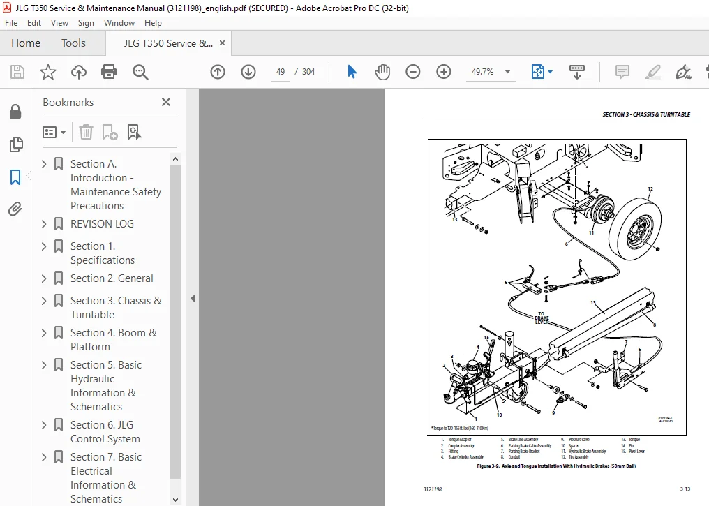
 - PDF DOWNLOAD")
 - PDF DOWNLOAD")