
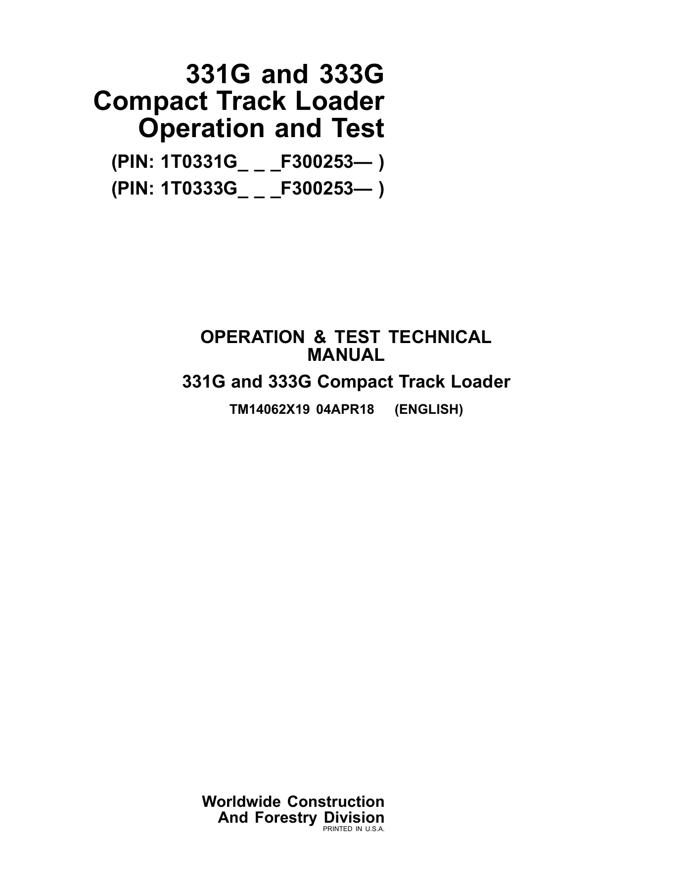
John Deere 331G 333G Compact Track Loader Operation and Test Manual TM14062X19
Original price was: $34.95.$20.95Current price is: $20.95.
Operation and Test Technical Manual for John Deere 331G and 333G Compact Track Loaders. Includes diagnostic trouble codes, operational checkout procedures, electrical and hydraulic system diagnostics, and testing information. Document TM14062X19, dated 04APR18, English.
Description
John Deere 331G and 333G Compact Track Loader Operation and Test Manual
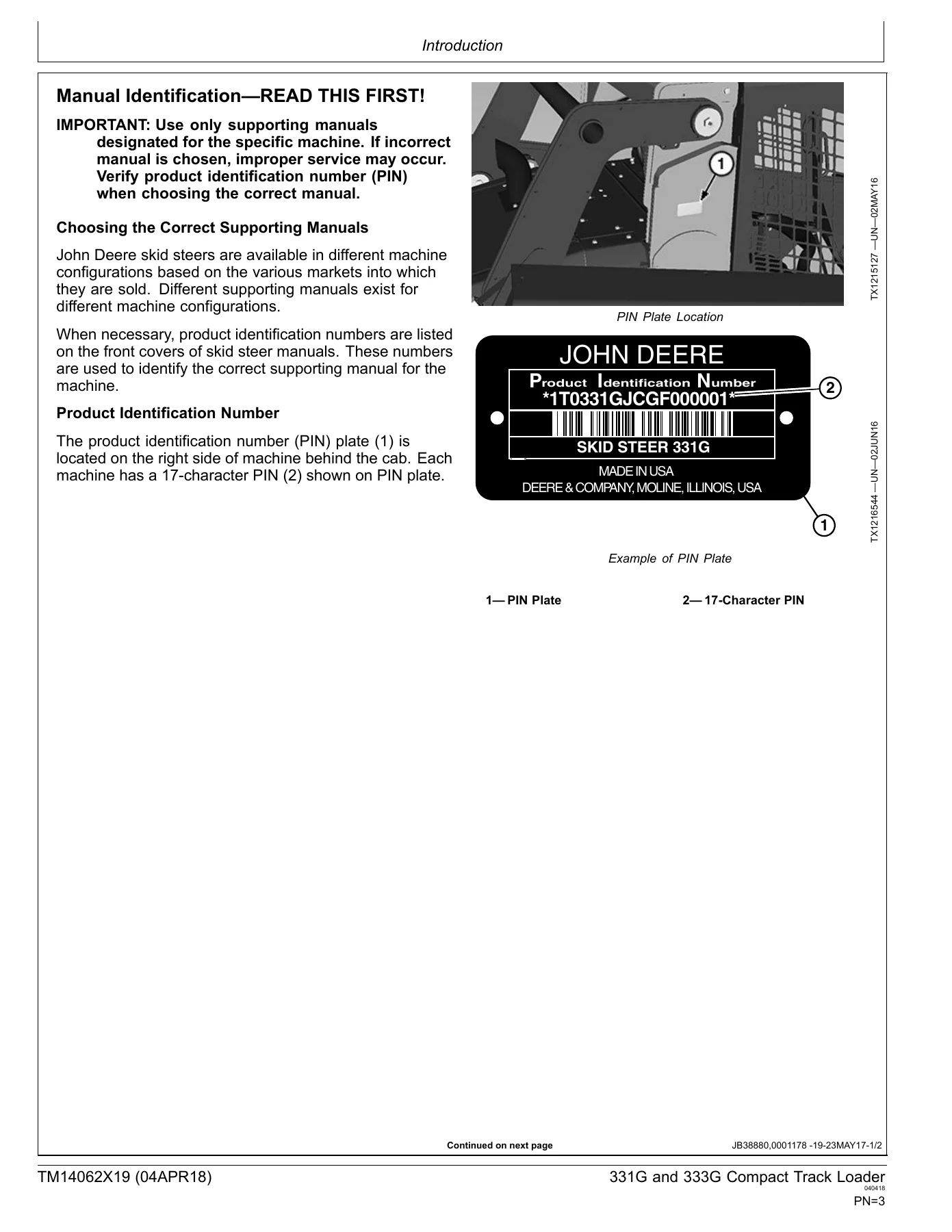
This Operation and Test Technical Manual covers the John Deere 331G and 333G Compact Track Loaders with PIN prefixes 1T0331G_ _ F300253— and 1T0333G _ F300253—. Published as document TM14062X19 on 04APR18, this English-language manual is written for the experienced technician and provides the diagnostic, testing, and operational checkout information needed to identify and resolve routine failures quickly.
File Details
- Manual Type: Operation and Test Technical Manual
- Brand: John Deere
- Models Covered: 331G and 333G Compact Track Loader
- Document Number: TM14062X19
- Date: 04APR18
- Language: English
- Format: PDF
Chapters Covered
- Section 9000 — General Information
- Group 01 — Safety
- Section 9001 — Diagnostics
- Group 05 — Dosing Control Unit (DCU) Diagnostic Trouble Codes
- Group 10 — Engine Control Unit (ECU) Diagnostic Trouble Codes
- Group 20 — Engagement and Monitor Unit (EMU) Diagnostic Trouble Codes
- Group 30 — Hydraulic Control Unit (HCU) Diagnostic Trouble Codes
- Group 40 — Left Joystick Controller (JSL) Diagnostic Trouble Codes
- Group 50 — Right Joystick Controller (JSR) Diagnostic Trouble Codes
- Group 60 — Sealed Switch Module (SSM) Diagnostic Trouble Codes
- Group 70 — Vehicle Control Unit (VCU) Diagnostic Trouble Codes
- Group 80 — Rear Camera Display (VC1) Diagnostic Trouble Codes
- Section 9005 — Operational Checkout Procedure
- Group 10 — Operational Checkout Procedure
- Section 9010 — Engine
- Group 05 — Theory of Operation
- Group 10 — System Diagrams
- Group 15 — Diagnostic Information
- Group 20 — Adjustments
- Group 25 — Tests
- Section 9015 — Electrical System
- Group 05 — Theory of Operation
- Group 10 — System Diagrams
- Group 15 — Diagnostic Information
- Group 16 — Monitor Operation
- Group 17 — Diagnostic Test Box
- Group 20 — Adjustments
- Group 25 — Tests
- Section 9020 — Power Train
- Group 05 — Theory of Operation
- Group 10 — System Diagrams
- Group 15 — Diagnostic Information
- Group 20 — Adjustments
- Section 9025 — Hydraulic System
- Group 05 — Theory of Operation
- Group 10 — System Diagrams
- Group 15 — Diagnostic Information
- Group 20 — Adjustments
- Group 25 — Tests
- Section 9026 — Hydrostatic System
- Group 05 — Theory of Operation
- Group 10 — System Diagrams
- Group 15 — Diagnostic Information
- Group 25 — Tests
- Section 9031 — Heating and Air Conditioning
- Group 05 — Theory of Operation
- Group 10 — System Diagrams
- Group 15 — Diagnostic Information
- Group 25 — Tests
- Section 9900 — Dealer Fabricated Tools
- Group 99 — Dealer Fabricated Tools
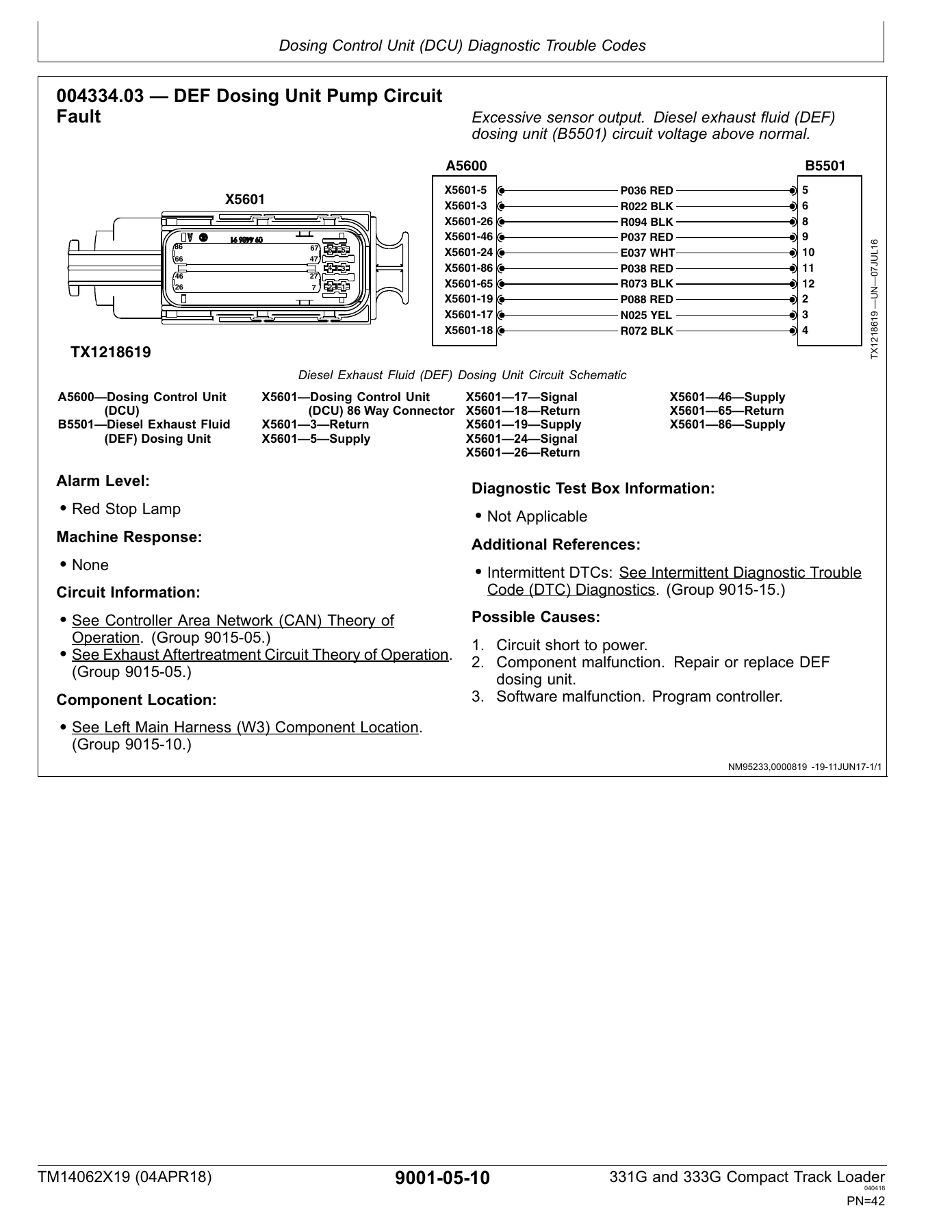
This manual is organized to help technicians quickly identify the majority of routine failures. Each group begins with summary listings of applicable essential tools, service equipment, other materials needed to do the job, service parts kits, specifications, wear tolerances, and torque values. The diagnostic trouble code sections provide SPN and FMI numbers, alarm levels, machine responses, circuit information, component locations, diagnostic test box information, and possible causes for each code.
Diagnostics and Testing
The diagnostic sections cover the Dosing Control Unit (DCU), Engine Control Unit (ECU), Engagement and Monitor Unit (EMU), Hydraulic Control Unit (HCU), Left Joystick Controller (JSL), Right Joystick Controller (JSR), Sealed Switch Module (SSM), Vehicle Control Unit (VCU), and Rear Camera Display (VC1). Each diagnostic trouble code entry includes the SPN and FMI number, alarm level, machine response, circuit information, component location, diagnostic test box information, additional references, and possible causes to guide systematic troubleshooting.
Engine diagnostics include service throttle, foot throttle, hand throttle, oil pressure, system voltage, vehicle ID, main relay, start aid, coolant temperature, air filter restriction, ECU communication, EGR communication, and DCU communication fault codes. The manual also covers exhaust aftertreatment circuit theory and DEF system diagnostics including DEF level, temperature, concentration, dosing unit pump, and tank heater coolant control valve circuits.
Operational Checkout Procedure
The Operational Checkout Procedure section provides step-by-step checks organized by machine state: switched power OFF and engine OFF, switched power ON and engine OFF, and switched power ON and engine ON. These checks help verify machine functions before and during operation.
Hydraulic and Hydrostatic Systems
The hydraulic system section covers hydraulic oil filter manifold operation, high flow pump operation, self-leveling valve operation, ride control operation, hydraulic pump operation, hydraulic fan operation, and hydraulic control valve operation. Diagnostic information addresses no hydraulic functions, boom will not raise or lower, bucket will not dump or curl, bucket will not self-level, boom and bucket drift, slow or no power, jerky or spongy functions, system noise, overheating, and fan system malfunctions. Tests include hydraulic system pressure release, port lock solenoid valve and spool test, hydraulic system relief valve test, charge pressure relief valve test, high flow relief valve test, circuit relief valve test, function drift test, hydraulic cylinder leakage test, hydraulic pump flow test, charge pump flow test, hydraulic fan motor speed test, hydraulic fan motor case drain test, and auxiliary coupler manifold leakage test.
The hydrostatic system section covers hydrostatic pump operation, charge pump operation, hydrostatic motor operation for two-speed machines, hydrostatic control valve operation, and park brake system operation. Diagnostic procedures address machine does not move, pump or motor noise, slow response to speed changes, low power, tracks powered on one side only, shifting issues, mistracking, and park brake hold or release problems. Tests include multi-function valve pressure relief test, hydrostatic pump flow test, hydrostatic pump mechanical neutral adjustment, hydrostatic pump control neutral adjustment, track speed test, and park brake release pressure test.
Heating and Air Conditioning
The HVAC section covers the air conditioning system cycle of operation, component location, diagnostic information for system does not operate, does not cool, runs constantly, heating system does not operate or warm, and interior windows fogging. Tests include R134a refrigerant cautions and handling, oil and refrigerant charge capacities, operational checks, visual inspection, compressor clutch test, refrigerant leak test, hose and tubing inspection, high/low pressure switch test, freeze control switch test, air conditioning system test, and operating pressure diagnostic chart.
Electrical System
The electrical system section covers starting circuit theory, Controller Area Network (CAN) theory, rear camera circuit theory, Engine Control Unit (ECU) circuit theory, exhaust aftertreatment circuit theory, Engagement and Monitor Unit (EMU) circuit theory, lighting circuit theory, hydraulic system control circuit theory, backup alarm circuit theory, Quik-Tatch circuit theory, JDLink circuit theory, hydrostatic system control circuit theory, and hydraulic fan control circuit theory. System diagrams include electrical schematic symbols, fuse and relay specifications, and harness component locations and wiring diagrams for the rear engine, cab, left main, right main, dual flasher, JDLink, radio, rear camera, attachment control frame, attachment control boom, heater and air conditioner, creep mode speed switch, engine interface, engine, engine fuel system, pedal interface, joystick jumper, DEF control valve, Quik-Tatch frame, Quik-Tatch boom, and Quik-Tatch actuator harnesses.
Power Train
The power train section covers system operation, component location, and diagnostic information for loose track, tight track, frequent track tension adjustment, excessive oil leakage from idlers and rollers, popping of track, and individual undercarriage component wear. Adjustments include check and adjust track tension.
Monitor Operation and Diagnostic Test Box
The monitor operation section covers service mode, exhaust filter service cleaning, exhaust filter set auto clean, shift mode, codes, diagnostics for switches, sensors, left and right joystick, speeds, VCU outputs, EMU outputs, ECU outputs, VCU power, EMU power, ECU power, controller info, calibration values, antitheft master code, calibration, owner controls, and antitheft security system configuration, enable, and operation. The diagnostic test box section covers setup and functional test, two wire sensor circuit checks, three wire sensor circuit checks, and adjustments for hydrostatic system calibration, boom and bucket calibration, auxiliary hydraulics calibration, manual tracking adjustment, and electrohydraulic foot pedal calibration.
Buy the John Deere 331G 333G Operation and Test Manual
This John Deere 331G 333G Compact Track Loader Operation and Test Manual gives you the diagnostic and testing information needed to service these machines correctly. Whether you are troubleshooting a fault code, performing an operational checkout, testing hydraulic or hydrostatic system pressures, or diagnosing an HVAC issue, this manual provides the procedures and specifications to get the job done. Having the correct procedures and specifications matters because compact track loaders are complex machines with interconnected electrical, hydraulic, and hydrostatic systems. Using the wrong values or skipping diagnostic steps can lead to misdiagnosis, unnecessary parts replacement, or machine damage.
IMAGES PREVIEW
Upon purchase, you receive an instant PDF download of the John Deere 331G 333G Operation and Test Manual TM14062X19. No shipping, no waiting. The file can be viewed on any device and printed for use in the shop.
Reviews
There are no reviews yet.