John Deere 350DLC Excavator Operation and Tests TECHNICAL MANUAL TM2359 – PDF DOWNLOAD
$34.95
John Deere 350DLC Excavator Operation and Tests TECHNICAL MANUAL TM2359 – PDF DOWNLOAD
Description
John Deere 350DLC Excavator Operation and Tests TECHNICAL MANUAL TM2359 – PDF DOWNLOAD
FILE DETAILS:
John Deere 350DLC Excavator Operation and Tests TECHNICAL MANUAL TM2359 – PDF DOWNLOAD
Language : English
Pages :764
Downloadable : Yes
File Type : PDF
IMAGES PREVIEW OF THE MANUAL:
DESCRIPTION:
John Deere 350DLC Excavator Operation and Tests TECHNICAL MANUAL TM2359 – PDF DOWNLOAD
Foreword
- This manual is written for an experienced technician. Essential tools required in performing certain service work are identified in this manual and are recommended for use. Live with safety: Read the safety messages in the introduction of this manual and the cautions presented throughout the text of the manual.
- This is the safety-alert symbol. When you see this symbol on the machine or in this manual, be alert to the potential for personal injury. Technical manuals are divided in two parts: repair and operation and tests. Repair sections tell how to repair the components.
- Operation and tests sections help you identify the majority of routine failures quickly. Information is organized in groups for the various components requiring service instruction. At the beginning of each group are summary listings of all applicable essential tools, service equipment and tools, other materials needed to do the job, service parts kits, specifications, wear tolerances, and torque values.
- Technical Manuals are concise guides for specific machines. They are on-the-job guides containing only the vital information needed for diagnosis, analysis, testing, and repair. Fundamental service information is available from other sources covering basic theory of operation, fundamentals of troubleshooting, general maintenance, and basic type of failures and their causes.
TABLE OF CONTENTS:
John Deere 350DLC Excavator Operation and Tests TECHNICAL MANUAL TM2359 – PDF DOWNLOAD
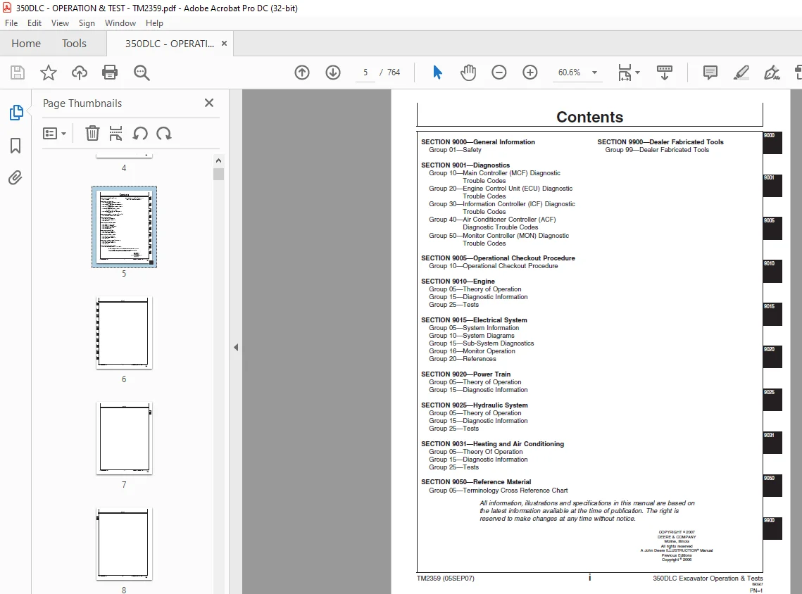
Contents 5
General Information 9
Safety 11
Recognize Safety Information 11
Follow Safety Instructions 11
Operate Only If Qualified 11
Wear Protective Equipment 12
Avoid Unauthorized Machine Modifications 12
Add Cab Guarding for Special Uses 13
Inspect Machine 13
Stay Clear of Moving Parts 13
Avoid High-Pressure Oils 14
Beware of Exhaust Fumes 14
Prevent Fires 15
Prevent Battery Explosions 15
Handle Chemical Products Safely 16
Dispose of Waste Properly 16
Prepare for Emergencies 16
Use Steps and Handholds Correctly 17
Start Only From Operator’s Seat 17
Use and Maintain Seat Belt 17
Prevent Unintended Machine Movement 18
Avoid Work Site Hazards 18
Keep Riders Off Machine 19
Avoid Backover Accidents 19
Avoid Machine Tip Over 20
Use Special Care When Lifting Objects 20
Add and Operate Attachments Safely 21
Prevent Unintended Detonation of Explosive Devices 21
Park and Prepare for Service Safely 22
Service Cooling System Safely 22
Remove Paint Before Welding or Heating 23
Make Welding Repairs Safely 23
Drive Metal Pins Safely 24
Diagnostics 25
Main Controller (MCF) Diagnostic Trouble Codes 29
Main Controller (MCF) Diagnostic Trouble Codes 29
1100002 — Abnormal EEPROM 29
Controller Hardware Diagnostics 29
Engine Control Unit (ECU) Diagnostic Trouble Codes147
Engine Control Unit (ECU) Diagnostic Trouble Codes147
Information Controller (ICF) Diagnostic Trouble Codes149
Information Controller (ICF) Diagnostic Trouble Codes149
1400002 — Abnormal CAN Communication149
1400102 — ICF: Flash Memory: Read / Write Error149
1400202 — ICF: External RAM: Read / Write Error150
1400302 — ICF: EEPROM: Sum Check Error150
1400602 — ICF: Satellite Communication Terminal: Communication Error150
1400802 — ICF: Abnormal Internal RAM150
1410002 — Satellite Communication Terminal: Abnormal EEPROM151
1410102 — Satellite Communication Terminal: Abnormal IB / OB Queue151
1410202 — Satellite Communication Terminal: Abnormal Local Loop Back151
1410302 — Satellite Communication Terminal: The Satellite is not found151
1410402 — Satellite Communication Terminal: Fail 1 of Remote Loop Back152
1410502 — Satellite Communication Terminal: Tail 2 of Remote Loop Back152
1410602 — Satellite Communication Terminal: Sending and Receiving Data are Mismatched152
Air Conditioner Controller (ACF) Diagnostic Trouble Codes153
Air Conditioner Controller (ACF) Diagnostic Trouble Codes153
21 — Mix Door Open Circuit153
Harness Diagnostics153
Theory of Operation203
Engine Oil Sampling Port Location203
Engine Fuel System Component Location204
Engine Cooling System Component Location208
Engine Speed Control System Operation210
Diagnostic Information215
PowerTech Plus™ 90 L (6090) John Deere Engines215
Tests217
Radiator217
Temperature Differential Check217
Electrical System219
System Information221
Electrical Diagram Information221
System Diagrams231
Explanation of Wire Markings231
Fuse and Relay Specifications232
System Functional Schematic, Component Location, and Wiring Diagram Master Legend236
System Functional Schematic242
JDLink™ System Functional Schematic—If Equipped250
Cab Harness (W1) Component Location252
Cab Harness (W1) Wiring Diagram254
Machine Harness (W2) Component Location258
Machine Harness (W2) Wiring Diagram260
Monitor Harness (W3) Component Location262
Monitor Harness (W3) Wiring Diagram264
Engine Harness (W5) Component Location266
Engine Harness (W5) Wiring Diagram270
Engine Interface Harness (W7) Component Location272
Engine Interface Harness (W7) Wiring Diagram274
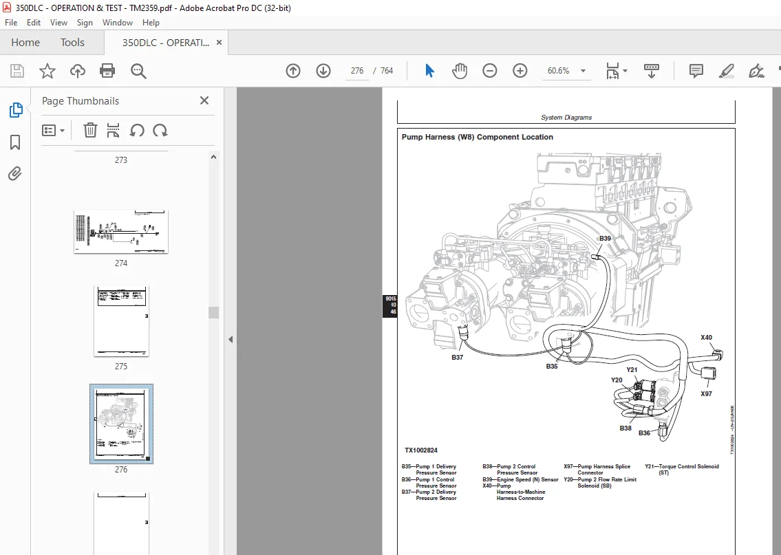
Pump Harness (W8) Component Location276
Pump Harness (W8) Wiring Diagram278
Right Console Harness (W11) Component Location280
Right Console Harness (W11) Wiring Diagram282
Auxiliary Fuse Box Harness (W13) Component Location284
Auxiliary Fuse Box Harness (W13) Wiring Diagram288
Heated Air Seat Harness (W14) Component Location290
Heated Air Seat Harness (W14) Wiring Diagram292
Multi-Function Pilot Control Lever Harness (W15) Component Location294
Multi-Function Pilot Control Lever Harness (W15) Wiring Diagram296
Pilot Shutoff Switch Harness (W17) Component Location297
Pilot Shutoff Switch Harness (W17) Wiring Diagram298
JDLink™ System Harnesses (W50, W51, W52, W53, and W54) Component Location—If Equipped300
Machine Information Gateway (MIG) Harness (W50) Wiring Diagram—If Equipped302
GlobalTRACS® Terminal (GTT) Harness (W51) Wiring Diagram—If Equipped304
JDLink™ CAN Harness (W52) Wiring Diagram—If Equipped306
JDLink™ Power Harness (W53) Wiring Diagram—If Equipped308
JDLink™ Jumper Harness (W54) Wiring Diagram—If Equipped310
Sub-System Diagnostics311
Controller Area Network (CAN) Theory of Operation311
Starting and Charging Circuit Theory of Operation312
Monitor Controller Circuit Theory of Operation314
Engine Control Unit (ECU) Circuit Theory of Operation318
Main Controller (MCF) Circuit Theory of Operation321
Information Controller (ICF) Circuit Theory of Operation326
Travel Alarm Circuit Theory of Operation328
Windshield Wiper and Washer Circuit Theory of Operation330
Pilot Shutoff Circuit Theory of Operation332
Monitor Operation335
Monitor Menu Operation335
Monitor Service Menu Operation335
References339
Monitor Data Items339
Reading Diagnostic Trouble Codes with Monitor Display340
JDLink™ Connection Procedure—If Equipped343
Service ADVISOR™ Diagnostic Application345
Service ADVISOR™ Connection Procedure346
Reading Diagnostic Trouble Codes with Service ADVISOR™ Diagnostic Application347
Dr ZX Diagnostic Application350
Personal Digital Assistant (PDA) Connection to Excavator Using Dr ZX Application350
Reading Diagnostic Trouble Codes With Dr ZX354
Main Controller (MCF) Monitor Display Using Dr ZX356
Main Controller (MCF) Special Function Using Dr ZX365
Main Controller (MCF) Setup Using Dr ZX369
Engine Control Unit (ECU) Monitor Display Using Dr ZX381
Engine Control Unit (ECU) Special Function Using Dr ZX386
Monitor Controller Monitoring Using Dr ZX387
Monitor Controller Various Setup Using Dr ZX390
Dr ZX Password Change394
Machine Information Center (MIC) Application397
Information Controller (ICF) Initialization397
Information Controller (ICF) Model and Serial Number401
Information Controller (ICF) Date and Time405
Information Controller (ICF) Control Data: Initialize409
Information Controller (ICF) Satellite Terminal412
Information Controller (ICF) Data Download413
Information Controller (ICF) Recorded Data417
Fuse Test420
Relay Test424
Pressure Sensor Test425
Solenoid Test426
Proportional Solenoid Test427
Temperature Sensor Test428
Alternator Test429
Electrical Component Checks431
Component Checks431
431
431
432
432
432
433
433
Battery Remove and Install434
Rear Cover Remove and Install436
Main Controller (MCF) Remove and Install437
Engine Control Unit (ECU) Remove and Install438
Information Controller (ICF) Remove and Install439
Monitor Controller Remove and Install439
Key Switch Remove and Install441
Switch Panel Remove and Install442
Travel Alarm Remove and Install443
Travel Alarm Cancel Switch Remove and Install444
Disconnect Tab Retainer Connectors445
Disconnecting Spring Wire Clip Connectors445
Replace DEUTSCH™ Connectors446
Replace DEUTSCH™ Rectangular or Triangular Connectors447
Install DEUTSCH™ Contact448
Replace WEATHER PACK™Connector449
Install WEATHER PACK™Contact450
Replace (Pull Type) Metri-Pack™ Connectors451
Replace (Push Type) Metri-Pack™ Connectors452
Replace CINCH™ Connectors453
Install CINCH™ Contact455
Repair 32 and 48 Way CINCH™ Connectors456
Remove Connector Body from Blade Terminals459
Power Train461
Theory of Operation463
Track Adjuster and Recoil Spring Operation463
Travel Gearbox Operation464
Diagnostic Information467
Diagnose Undercarriage Components Malfunctions467
Noisy or Loose Track Chain467
467
467
467
Tight Track Chain467
467
468
Frequent Track Chain Sag Adjustment Required468
468
Excessive Oil Leakage From Front Idler, Track Rollers, or Carrier Rollers468
468
Bent Track Shoes468
469
469
469
“Popping” Of Track469
469
469
Cracked Track Link470
470
470
Chipped Link Rails470
470
Individual Undercarriage Component Wear470
471
Measure Swing Bearing Wear471
Hydraulic System475
Theory of Operation477
Hydraulic System Diagram and Operation477
Fan Drive System Operation480
Pilot System Diagram and Operation484
Pilot Pump, Pressure Regulating Valve and Filter Operation486
Pilot Shutoff Solenoid Valve Operation487
Pilot Control Valve Operation490
Travel Pilot Control Valve Operation492
Pilot Operation of Control Valve Operation494
Pilot Signal Manifold Operation496
Pump and Drive Gearbox Operation508
Pump Regulator Operation512
Engine Speed Sensing Control Circuit Operation519
Control Valve Operation521
Control Valve534
Check Valves Identification And Operation534
Main Relief and Power Digging Valve537
Circuit Operation537
Circuit Relief and Anticavitation Valve Operation542
Travel Flow Combiner Valve544
Operation544
Boom Lower Meter-In Cut Valve Operation547
Boom Regenerative Valve Circuit Operation549
Dig Regenerative Valve Circuit Operation552
Arm Regenerative Valve Circuit Operation556
Bucket Regenerative Valve Circuit Operation560
Boom and Arm Reduced Leakage Valves Operation564
Arm 1 (Swing Priority) Flow Rate Valve Circuit Operation566
Swing Reduction Gearbox Operation567
Swing Motor, Crossover Relief Valve, and Make-Up Check Valve Operation568
Swing Motor Park Brake Release Circuit Operation571
Center Joint Operation572
Travel Motor and Park Brake Valve Operation574
Travel Motor Speed Circuit Operation582
Cylinder Operation586
Return Filter Operation587
Diagnostic Information589
Diagnose Hydraulic System Malfunctions589
All Hydraulic Functions Slow589
Pump 1, Pump 2, and Pilot Pump Line Identification619
Control Valve Line Identification620
Swing Motor Line Identification—350DLC624
Pilot Control Valve-to-Pilot Signal Manifold Component Location—Excavator Pattern626
Pilot Control Valve-to-Pilot Signal Manifold Component Location—Backhoe Pattern628
Pilot Signal Manifold-to-Control Valve Line Connection630
Travel System Component Location634
Travel Hydraulic System Line Connection636
Hydraulic System Schematic638
Fan Drive Hydraulic System Schematic648
Hydraulic System Component Location650
Hydraulic System Line Connections652
Fan Drive System Component Location653
Tests655
JT05800 Digital Thermometer Installation655
JT02156A Digital Pressure/Temperature Analyzer655
Hydraulic Oil Cleanup Procedure Using Portable Filter Caddy656
Hydraulic Oil Warm-Up Procedure657
Cylinder Drift Test—Boom, Arm, and Bucket660
Pilot Pressure Regulating Valve Test and Adjustment662
Control Valve Spool Actuating Pilot Pressure Test666
Main Relief and Power Digging Valve668
Test and Adjustment668
Circuit Relief Valve672
Test and Adjustment672
Swing Motor Crossover Relief Valve Test and Adjustment675
Travel Motor Crossover Relief Valve Test and Adjustment678
Torque Control Solenoid Valve681
Test and Adjustment681
Dig Regenerative Solenoid Valve Test and Adjustment685
Arm Regenerative Solenoid Valve Test and Adjustment689
Power Digging Solenoid Valve Test and Adjustment693
Travel Speed Solenoid Valve Test and Adjustment697
Pump Control Pilot Pressure701
Signal Test701
Pump Regulator Test and Adjustment—Minimum Flow704
Pump Regulator Test and Adjustment—Maximum Flow706
Pump Flow Test708
Swing Motor Leakage Test711
Travel Motor Leakage Test713
Fan Speed Test715
Fan Drive Pump Flow Test717
Heating and Air Conditioning719
Theory Of Operation721
Air Conditioning System Cycle of Operation721
Diagnostic Information723
Diagnose Air Conditioning System Malfunctions723
Diagnose Heating System Malfunctions727
Heater and Air Conditioner Diagnostic Trouble Code Check729
Heater and Air Conditioner Component Location734
Tests737
Refrigerant Cautions and Proper Handling737
Heater and Air Conditioner Operational Checks738
Visual Inspection of Components738
S.M 6/1/25