tm1610 – 410e backhoe loader operation and test
+Table of Contents
Foreword
HELP!! HELP!! HELP!! HELP!!
+Section 9000: General Information
+Group 01: Safety Information
Handle Fluids Safely-Avoid Fires
Prevent Battery Explosions
Prepare for Emergencies
Prevent Acid Burns
Handle Chemical Products Safely
Avoid High-Pressure Fluids
Park Machine Safely
Support Machine Properly
Wear Protective Clothing
Work in Clean Area
Service Machines Safely
Work In Ventilated Area
Illuminate Work Area Safely
Replace Safety Signs
Use Proper Lifting Equipmentp. 3
Remove Paint Before Welding or Heatingp. 3
Avoid Heating Near Pressurized Fluid Linesp. 3
Keep ROPS Installed Properlyp. 3
Service Tires Safelyp. 3
Practice Safe Maintenancep. 3
Use Proper Toolsp. 3
Dispose of Waste Properlyp. 3
Live With Safetyp. 3
+Group 02: General Specificationsp. 3
410E Backhoe Loader Dimensionsp. 3
410E Backhoe Loader Specificationsp. 3
Other Information-410E Backhoe Loaderp. 3
410E Backhoe Loader Weightp. 3
410E Backhoe and Loader Bucketsp. 3
410E Backhoe Loader Drain and Refill Capacitiesp. 3
410E Backhoe Loader Lifting Capacities-Standard Dipperstickp. 3
410E Backhoe Loader Lifting Capacities-Extendible Dipperstick (Retracted)p. 3
410E Backhoe Loader Lifting Capacities-Extendible Dipperstick (Extended)p. 3
+Group 03: Torque Valuesp. 3
Hardware Torque Specificationsp. 3
ROPS Torque Specificationsp. 3
Metric Bolt and Cap Screw Torque Values
Additional Metric Cap Screw Torque Values
Unified Inch Bolt and Cap Screw Torque Values
O-Ring Groove Connections
Check Oil Lines And Fittings
Service Recommendations for O-Ring Boss Fittings
Service Recommendations for Flat Face O-Ring Seal Fittings
Service Recommendations for Metric Series Four Bolt Flange Fitting
Service Recommendations For Inch Series Four Bolt Flange Fittings
+Group 04: Fuels and Lubricants
Diesel Fuel
Low Sulfur Diesel Fuel Conditioner
Diesel Fuel Storage
Do Not Use Galvanized Containers
Fuel Tank
Diesel Engine Oil
Transmission, Rear Axle and Mechanical Front Wheel Drive Oil
Hydraulic Oil
Diesel Engine Coolant
Grease
Grease For Extendible Dipperstick
Alternative and Synthetic Lubricants
Lubricant Storage
Mixing of Lubricants
+Section 9005: Operational Checkout Procedure
+Group 10: Operational Checkout Procedure
Operational Checkout Procedure
+Section 9010: ENGINE
+Group 05: Theory of Operation
PowerTech 4.5 L (4045) John Deere Engine-Use CTM104
Engine-Sectional View
General Engine Description
+Group 15: Diagnostic Information
PowerTech 4.5 L (4045) John Deere Engine-Use CTM104
Make Visual Inspection of Engine and Supporting Systems
Diagnose Engine Malfunctions
+Group 20: Adjustments
PowerTech 4.5 L (4045) John Deere Engine-Use CTM104
JT05801 Clamp-On Electronic Tachometer Installation
Adjust Speed Control Lever Tension
Slow and Fast Idle
Engine Speed Control Linkage
+Group 25: Tests
PowerTech 4.5 L (4045) John Deere Engine-Use CTM104
JT05801 Clamp-On Electronic Tachometer Installation
JT05800 Digital Thermometer Installationp. 4
Air Intake System Leakage Testp. 4
Radiator Air Flow Testp. 4
Turbocharger Boost Pressure-Engine Performance Testp. 4
Injection Pump Timingp. 4
Fuel Line Leakage Testp. 4
+Section 9015: Electrical Systemp. 4
+Group 05: System Informationp. 4
Visually Inspect Electrical Systemp. 4
Malfunctionsp. 4
High Resistance Circuitp. 4
Open Circuitp. 4
Grounded Circuitp. 4
Shorted Circuitp. 4
Multimeterp. 4
Seven Step Electrical Test Procedurep. 4
System Functional Schematic Informationp. 4
Reading a System Functional Schematicp. 4
Reading a Component Location Diagramp. 4
Electrical Schematic Symbolsp. 4
+Group 10: System Diagramsp. 4
Component Identification Tablep. 4
Fuse (Blade-Type) Color Codesp. 4
Fuse Specifications
Wiring and Schematic Diagrams Legend
System Functional Schematic Section Legend
System Functional Schematic
Cab Roof Harness (W5) Component Location
Cab Roof Harness (W5) Connectors, Wire and Pin Location
Cab Side Console Harness (W6) Component Location
Cab Side Console Harness (W6) Connectors, Wire and Pin Location
Front Console Harness (W7) Component Location
Front Console Harness (W7) Component Location (With Optional Power Shift)
Front Console Harness (W7) Connectors, Wire and Pin Location
Engine Harness (W8) Component Location
Engine Harness (W8) Component Location (With Optional Power Shift)
Engine Harness (W8) Connectors, Wire and Pin Location
Blower Harness (W10) Component Location
Blower Harness (W10) Connectors, Wire and Pin Location
Radio Harness (W12) Component Location
Radio Harness (W12) Connectors, Wire and Pin Location
Air Conditioning Compressor Harness (W11) Component Location
Air Conditioning Compressor Harness (W11) Connectors, Wire and Pin Location
Selective Flow Valve Harness (W15) Component Location
Selective Flow Valve Harness (W15) Connectors, Wire and Pin Location
Ride Control Harness (W17) Component Location
Ride Control Harness (W17) Connectors, Wire and Pin Location
Pin Disconnect Harness (W18) Component Location
Pin Disconnect Harness (W18) Connectors, Wire and Pin Location
+Group 15: Sub-System Diagnostics
Power Circuit Operational Information
Power Circuit Theory Of Operation
Power Circuit Schematic
Sub-System Diagnostics/Power Circuit
Start Circuit Operational Information
Start Circuit Theory of Operation
Start Circuit Schematic
Sub-System Diagnostics/Start Circuit
Charging Circuit Operational Information
Charging Circuit Theory of Operation
Charge Circuit Schematic
Sub-System Diagnostics/Charging Circuit
Differential Lock Circuit Operational Information
Differential Lock Circuit Theory of Operation
Differential Lock Circuit Schematic
Sub-System Diagnostics/Differential Lock Circuit
MFWD Circuit Operational Information
MFWD Circuit Theory of Operation
MFWD Circuit Schematicp. 5
Sub-System Diagnostics/MFWD Circuitp. 5
Display Monitor Circuit Operational Informationp. 5
Display Monitor Circuit Theory Of Operationp. 5
Display Monitor Circuit Schematicp. 5
Sub-System Diagnostics/Display Monitorp. 5
Indicator Circuit Specificationsp. 5
Indicator Circuit Operational Informationp. 5
Indicator Circuit Theory of Operationp. 5
Indicator Circuit Schematicp. 5
Sub-System Diagnostics/Indicator Circuitp. 5
Park Brake/FNR Circuit Operational Informationp. 5
Park Brake/FNR Circuit Specificationsp. 5
Park Brake/Neutral Disconnect Circuit (Manual Shift) Theory Of Operationp. 5
Park Brake/FNR Circuit (Manual Shift) Schematicp. 5
Park Brake/FNR Circuit (Power Shift) Theory of Operationp. 5
Park Brake/FNR Circuit (Power Shift) Schematicp. 5
Sub-System Diagnostics/Park Brake/FNR Circuitp. 5
Ride Control Circuit Operational Informationp. 5
Ride Control Circuit Theory of Operationp. 5
Ride Control Circuit Schematicp. 5
Sub-System Diagnostics/Ride Control Circuitp. 5
Selective Flow Valve Circuit Operational Informationp. 5
Selective Flow Valve Circuit Theory of Operation
Selective Flow Valve Circuit Schematic
Sub-System Diagnostics/Selective Flow Valve Circuit
Pin Disconnect Circuit Operational Information
Pin Disconnect Circuit Theory of Operation
Pin Disconnect Circuit Schematic
Sub-System Diagnostics/Pin Disconnect Circuit
+Group 20: References
Alternators and Starting Motors-Use CTM77
JT05801 Clamp-On Electronic Tachometer Installation
Battery Operation
Battery Specifications
Diagnose Battery Malfunctions
Check Battery Electrolyte Level and Terminals
Using Booster Batteries-12 Volt System
Alternator Operation-65 Amp Bosch and 95 Amp Bosch
Alternator Operation-65 Amp Bosch and 95 Amp Bosch (Continued)
Tachometer Calibration (S.N. -852337)
Tachometer Calibration (S.N. 852338- )
+Section 9020: Power Train
+Group 05: Theory of Operation
Forward, Reverse, Low Range Forward and Third Speed Clutch Pack Operation
Power Shift High Range Forward, First Speed and Second Speed Clutch Packs
Manual Shift Power Train Overview
Torque Converter Operation
Manual Shift Synchronizer Operation
Transmission Pump Operation
Transmission Filter Operation
Manual Shift Transmission Operation-First Gear Forward
Manual Shift Transmission Operation-Third Gear Reverse
Power Shift Power Train Overview
Power Shift Transmission Gear Flow
Mechanical Front Wheel Drive (MFWD) Operation
Manual Shift Transmission Control Valve Operation
Manual Shift Transmission Control Circuit-Neutral With Park Brake Off
Manual Shift Transmission Control Circuit-Forward
Manual Shift Transmission Control Circuit-Reverse
Power Shift Transmission Clutch Engagement And Solenoids Activated
Power Shift Transmission Control Circuit-Neutral With Park Brake Off
Power Shift Transmission Control Valve and Shift Valve Operation-Neutral
Power Shift Transmission Control Circuit-First Forward
Power Shift Transmission Control Valve and Shift Valve-First Forward
Power Shift Transmission Control Circuit-High Range (Fourth) Forward
Power Shift Transmission Control Valve and Shift Valve-High Range (Fourth) Forward
Power Shift Transmission Control Circuit-First Reversep. 6
Power Shift Transmission Control Valve and Shift Valve-First Reversep. 6
Manual Shift Modulation Valve Operationp. 6
Power Shift Modulation Valve Operationp. 6
Differential Operationp. 6
Differential Lock Operationp. 6
John Deere Brake Valve Operationp. 6
Service Brake Operationp. 6
MICO Power Boost Brake Valve-Neutral Positionp. 6
MICO Power Boost Brake Valve-Both Pedals Applied Positionp. 6
MICO Power Boost Brake Valve-One Pedal Applied Positionp. 6
MICO Power Boost Brake Valve-Both Pedals Applied, Engine Off Positionp. 6
Park Brake Operationp. 6
MFWD Differential Operation-Unequal Tractionp. 6
MFWD Differential Operation-Equal Traction-If Equippedp. 6
+Group 15: System Diagnostic Informationp. 6
Diagnose Manual Shift Power Train Malfunctionp. 6
Diagnose Power Shift Power Train Malfunctionp. 6
Diagnose MFWD Malfunctionp. 6
Diagnose Rear Axle Malfunctionp. 6
Hydraulic Circuit Symbolsp. 6
+Group 20: Adjustmentsp. 6
Adjust Brake Pedals and Equalizing Valvesp. 6
Bleeding Brakes
Checking and Adjusting Toe-In
+Group 25: Tests
JT05801 Clamp-On Electronic Tachometer Installation
JT05800 Digital Thermometer Installation
Transmission Oil Warm-Up Procedure
Manual Shift Transmission Overall Test Connections, Ports, and Locations
Power Shift Transmission Overall Test Connections, Ports, and Locations
Torque Converter Stall Speed Test
Converter-In Relief Valve Test
Brake Valve Leakage Test
Park Brake Release Pressure Test
System Pressure Test
Manual Shift Forward and Reverse Clutch Pressure Test
Power Shift Low Range Forward, High Range Forward, Reverse and Speed Clutch Pressure Test
Reducing Valve Pressure Test
Modulation Valve Pressure Test
Differential Lock Pressure Test
MFWD Pressure Test-If Equipped
Cooler In and Cooler Out Pressure Test
Solenoid Circuit Leakage Test
Pump Flow Test
+Section 9025: Hydraulic System
+Group 05: Theory of Operation
Backhoe Hydraulic System
Hydraulic Component Location
Hydraulic System Schematic-Neutral
Hydraulic System Schematic-Multiple Functions Activated
Hydraulic System Schematic-Neutral with Power Boost MICO Brake Valve
Hydraulic System Schematic-Multiple Functions Activated with Power Boost MICO Brake Valve
Hydrualic Component Location-Power Boost MICO Brake Valve Circuit- Both Pedals Applied
Load Sense Isolator
Load Sense With All Functions in Neutral
Load Sense With One Function Activated
Load Sense With Multiple Functions Activated
Load Sense With Multiple Functions Activated (One Function Stalled)
Hydraulic Pump-Neutral Operation
Hydraulic Pump-Full Stroke
Hydraulic Pump Controls-Neutral
Hydraulic Pump Controls-Function Metering
Hydraulic Pump Controls-Full Flow
Hydraulic Pump Controls-Flow Limited (High Pressure)
Hydraulic Filter Operation
Steering-No Steering
Steeringp. 7
Secondary Steeringp. 7
Ride Control Hydraulic Component Location Circuit-Offp. 7
Ride Control Valve Operation “OFF” Position-Continuedp. 7
Ride Control Hydraulic Component Location Circuit-On Positionp. 7
Ride Control Valve Operation “ON” Position-Continuedp. 7
Circuit Relief Valve without Anti-Cavitation-Loader and Backhoep. 7
Circuit Relief Valve with Anti-Cavitation-Loader and Backhoe-Continuedp. 7
Circuit Relief Valve with Anti-Cavitation-Loader and Backhoe (Continued)p. 7
Backhoe Auxiliary Flow Control Circuit Relief Valvep. 7
Stabilizer Valve Operationp. 7
Backhoe Inlet Section with Swing Section Activatedp. 7
Backhoe Auxiliary Flow Valve-Solenoid Energizedp. 7
Backhoe Swing Section-Swing Right Positionp. 7
Backhoe Boom Section-Boom Raise Positionp. 7
Backhoe Bucket Section-Bucket Curl Positionp. 7
Backhoe Crowd Section-Crowd In Positionp. 7
Backhoe Auxiliary Section-Neutralp. 7
Backhoe Endcap Outlet Sectionp. 7
Loader Inlet Endcap Section with Bucket Section Activatedp. 7
Loader Bucket Section-Bucket Rollback Positionp. 7
Loader Boom Section-Boom Raise Positionp. 7
Loader Auxiliary Section-Load Positionp. 7
Loader Endcap Outlet Section
+Group 15: Diagnostic Information
Use These Seven Basic Steps to Diagnose and Test the Hydraulic System
Make a Pretest Inspection and an Operation Check of the Machine
Hydraulic System Pretest
Diagnose Steering System Malfunctions
Diagnose Hydraulic System Problems
+Group 20: Adjustments
Loader Bucket Self-Leveling Linkage Indicator and Return-to-Dig Switch Adjustment
Loader Control Valve Linkage Adjustment
Backhoe Valve Linkage Adjustment
Stabilizer Valve Linkage Adjustment
+Group 25: Tests
Pre-Test Diagnostics
Diagnostics Flow Charts
JT05801 Clamp-On Electronic Tachometer Installation
JT05800 Digital Thermometer Installation
Hydraulic Oil Warm-Up Procedure
Pump Load Sense Differential Pressure Test
Pump Flow Test
Backhoe Load Sense and Loader Load Sense Relief Stall Pressure Test
Steering Load Sense Relief Valve Stall Pressure Test
Flow Limiter Test
Hydraulic Oil Cooler Restriction Test
Circuit Relief Valve Test with Remote Pump
Charging the Ride Control Accumulator
Charging the Ride Control Accumulator-Procedure “A” (14.2 in. accumulator)
Charging the Ride Control Accumulator-Procedure “B” (17.2 in. accumulator)
Ride Control Accumulator Discharge Procedure
Steering System Leakage Test
Steering Cylinder Leakage Test
Hydraulic Cylinder Drift Test Procedure
Function Drift Test
Cylinder Leakage Test
Stabilizer Valve Lockout Leakage Test
Cycle Time Specifications-410E
+Section 9031: Heating And Air Conditioning
+Group 05: Theory Of Operation
Proper Refrigerant Handling
R134A Refrigerant Cautions
Refrigerant Theory Of Operation
Air Conditioning Circuit Operational Information
Air Conditioning Circuit Theory Of Operation
Air Conditioning Circuit Schematic
Blower Circuit Operational Informationp. 8
Blower Circuit Theory Of Operationp. 8
Blower Circuit Schematicp. 8
Receiver/Dryer Operationp. 8
Expansion Valve Operationp. 8
Compressor Relief Valve Operationp. 8
Temperature Controlp. 8
+Group 10: System Operational Checksp. 8
Air Conditioning Operational Checksp. 8
+Group 15: Diagnostic Informationp. 8
Diagnose Air Conditioning Electrical Malfunctionsp. 8
Air Conditioning Component Locationp. 8
+Group 20: Adjustmentsp. 8
Special or Essential Toolsp. 8
Service Equipment and Toolsp. 8
Other Materialsp. 8
Proper Refrigerant Handlingp. 8
R134A Refrigerant Cautionsp. 8
R134A Compressor Oil Charge Checkp. 8
R134A Compressor Oil Removalp. 8
R134A Component Oil Chargep. 8
R134A Refrigerant Recovery, Recycling And Charging Station Installation Procedurep. 8
Recover R134A System
Evacuate R134A System
Charge R134A System
+Group 25: Test
Special or Essential Tools
Service Equipment and Tools
Proper Refrigerant Handling
R134A Refrigerant Cautions
R134A Air Conditioning System Test
Pressure Diagnostic Chart
Low Pressure Switch Test
High Pressure Switch Test
A/C Freeze Control Switch
Leak Testing
Refrigerant Hoses And Tubing Inspection
Foreword
HELP!! HELP!! HELP!! HELP!!
Handle Fluids Safely-Avoid Firesp. 10
Handle Fluids Safely-Avoid Fires
Handle Fluids Safely-Avoid Fires
Prevent Battery Explosionsp. 11
Prepare for Emergencies
Prevent Acid Burns
Handle Chemical Products Safely
Avoid High-Pressure Fluids
Park Machine Safelyp. 13
Support Machine Properly
Wear Protective Clothing
Work in Clean Areap. 14
Service Machines Safely
Work In Ventilated Area
Illuminate Work Area Safelyp. 15
Replace Safety Signs
Use Proper Lifting Equipment
Remove Paint Before Welding or Heatingp. 16
Avoid Heating Near Pressurized Fluid Lines
Keep ROPS Installed Properly
Service Tires Safelyp. 17
Practice Safe Maintenance
Use Proper Tools
Dispose of Waste Properly
Live With Safetyp. 19
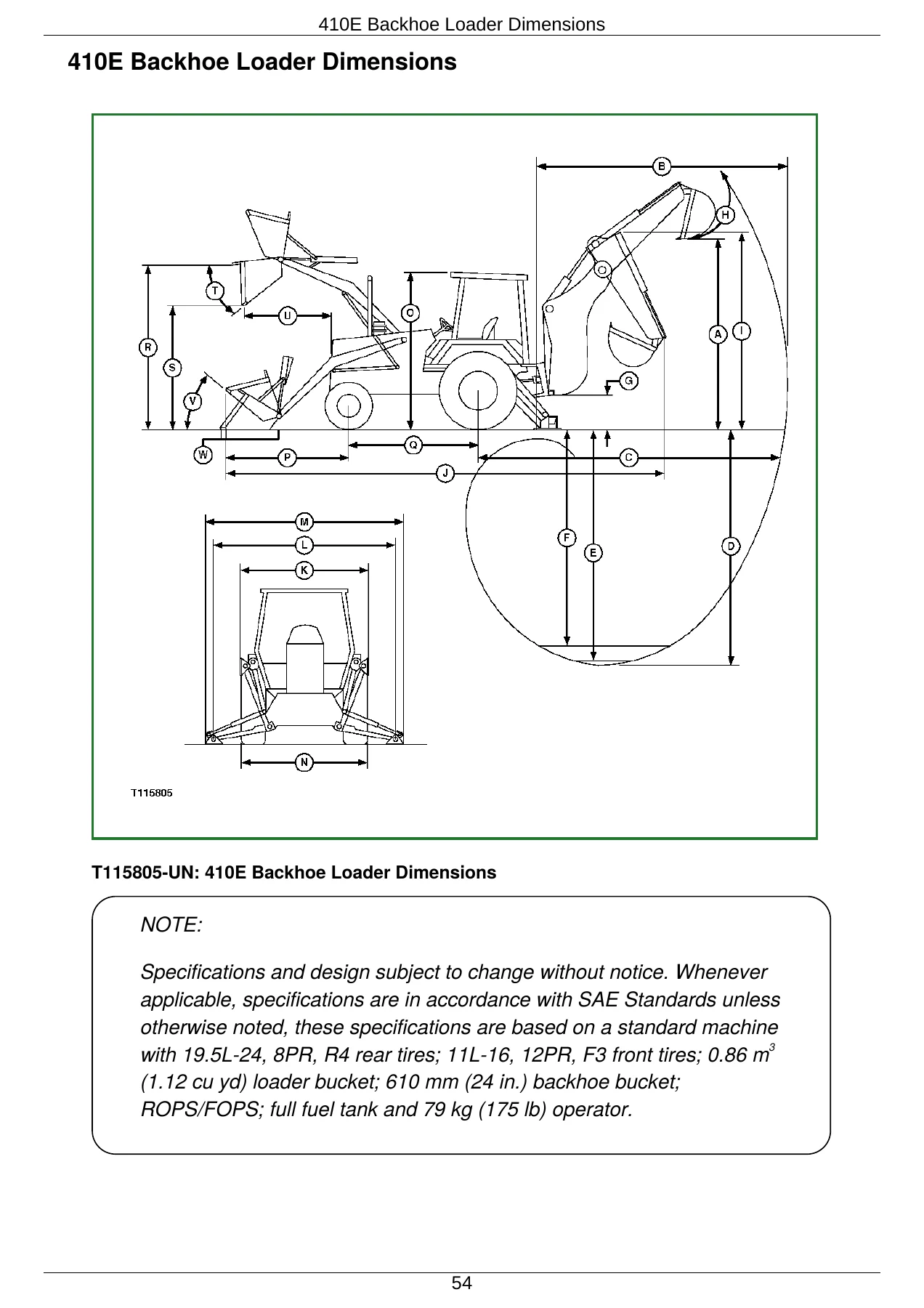
410E Backhoe Loader Dimensions
410E Backhoe Loader Dimensionsp. 21
410E Backhoe Loader Specifications
Other Information-410E Backhoe Loader
410E Backhoe Loader Weight
410E Backhoe and Loader Buckets
410E Backhoe Loader Drain and Refill Capacitiesp. 25
410E Backhoe Loader Lifting Capacities-Standard Dipperstick
410E Backhoe Loader Lifting Capacities-Extendible Dipperstick (Retracted)p. 26
410E Backhoe Loader Lifting Capacities-Extendible Dipperstick (Extended)
Hardware Torque Specifications
Hardware Torque Specificationsp. 27
ROPS Torque Specifications
Metric Bolt and Cap Screw Torque Values
Additional Metric Cap Screw Torque Valuesp. 28
Unified Inch Bolt and Cap Screw Torque Values
O-Ring Groove Connectionsp. 29
Check Oil Lines And Fittings
+Service Recommendations for O-Ring Boss Fittingsp. 30
Straight Fittingp. 30
Angle Fittingp. 30
Service Recommendations for Flat Face O-Ring Seal Fittings
Service Recommendations for Metric Series Four Bolt Flange Fitting
Service Recommendations For Inch Series Four Bolt Flange Fittings
Diesel Fuel
Diesel Fuel
Low Sulfur Diesel Fuel Conditionerp. 33
Diesel Fuel Storage
Do Not Use Galvanized Containers
Fuel Tank
Diesel Engine Oilp. 34
Transmission, Rear Axle and Mechanical Front Wheel Drive Oil
Hydraulic Oil
+Diesel Engine Coolantp. 35
Coolant Drain Intervalsp. 35
Grease
Grease For Extendible Dipperstickp. 36
Alternative and Synthetic Lubricants
Lubricant Storage
Mixing of Lubricants
Operational Checkout Procedurep. 37
Operational Checkout Procedure
Operational Checkout Procedure
PowerTech 4.5 L (4045) John Deere Engine-Use CTM104
PowerTech 4.5 L (4045) John Deere Engine-Use CTM104p. 81
PowerTech 4.5 L (4045) John Deere Engine-Use CTM104
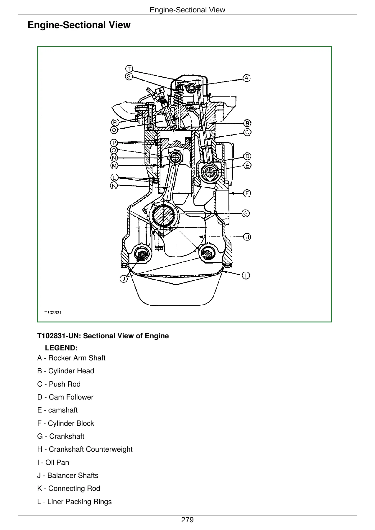
Engine-Sectional View
General Engine Description
PowerTech 4.5 L (4045) John Deere Engine-Use CTM104
PowerTech 4.5 L (4045) John Deere Engine-Use CTM104p. 82
Make Visual Inspection of Engine and Supporting Systems
Diagnose Engine Malfunctionsp. 83
PowerTech 4.5 L (4045) John Deere Engine-Use CTM104
PowerTech 4.5 L (4045) John Deere Engine-Use CTM104p. 86
JT05801 Clamp-On Electronic Tachometer Installation
Adjust Speed Control Lever Tension
Slow and Fast Idle
Engine Speed Control Linkage
PowerTech 4.5 L (4045) John Deere Engine-Use CTM104p. 87
PowerTech 4.5 L (4045) John Deere Engine-Use CTM104
JT05801 Clamp-On Electronic Tachometer Installation
JT05800 Digital Thermometer Installation
Air Intake System Leakage Test
Radiator Air Flow Test
Turbocharger Boost Pressure-Engine Performance Test
Injection Pump Timing
Fuel Line Leakage Testp. 91
Visually Inspect Electrical System
Visually Inspect Electrical System
Visually Inspect Electrical Systemp. 93
Malfunctions
High Resistance Circuit
Open Circuitp. 95
Grounded Circuit
Shorted Circuit
Multimeterp. 97
Seven Step Electrical Test Procedure
+System Functional Schematic Information
System Functional Schematic Diagram
Reading a System Functional Schematicp. 99
Reading a Component Location Diagram
Electrical Schematic Symbols
Component Identification Table
Component Identification Table
Fuse (Blade-Type) Color Codes
Fuse Specifications
Wiring and Schematic Diagrams Legend
System Functional Schematic Section Legend
System Functional Schematic
Cab Roof Harness (W5) Component Location
Cab Roof Harness (W5) Connectors, Wire and Pin Location
Cab Side Console Harness (W6) Component Locationp. 103
Cab Side Console Harness (W6) Connectors, Wire and Pin Location
Front Console Harness (W7) Component Location
Front Console Harness (W7) Component Location (With Optional Power Shift)p. 105
Front Console Harness (W7) Connectors, Wire and Pin Location
Engine Harness (W8) Component Location
Engine Harness (W8) Component Location (With Optional Power Shift)p. 106
Engine Harness (W8) Connectors, Wire and Pin Location
Blower Harness (W10) Component Location
Blower Harness (W10) Connectors, Wire and Pin Location
Radio Harness (W12) Component Location
Radio Harness (W12) Connectors, Wire and Pin Location
Air Conditioning Compressor Harness (W11) Component Locationp. 108
Air Conditioning Compressor Harness (W11) Connectors, Wire and Pin Location
Selective Flow Valve Harness (W15) Component Location
Selective Flow Valve Harness (W15) Connectors, Wire and Pin Location
Ride Control Harness (W17) Component Locationp. 109
Ride Control Harness (W17) Connectors, Wire and Pin Location
Pin Disconnect Harness (W18) Component Location
Pin Disconnect Harness (W18) Connectors, Wire and Pin Location
Power Circuit Operational Information
Power Circuit Operational Information
Power Circuit Theory Of Operation
Power Circuit Schematicp. 110
Sub-System Diagnostics/Power Circuit
Start Circuit Operational Informationp. 113
Start Circuit Theory of Operation
Start Circuit Schematic
Sub-System Diagnostics/Start Circuitp. 114
Charging Circuit Operational Information
Charging Circuit Theory of Operation
Charge Circuit Schematic
Sub-System Diagnostics/Charging Circuitp. 116
Differential Lock Circuit Operational Information
Differential Lock Circuit Theory of Operation
Differential Lock Circuit Schematic
Sub-System Diagnostics/Differential Lock Circuitp. 118
MFWD Circuit Operational Information
MFWD Circuit Theory of Operation
MFWD Circuit Schematicp. 119
Sub-System Diagnostics/MFWD Circuit
Display Monitor Circuit Operational Information
Display Monitor Circuit Theory Of Operationp. 120
Display Monitor Circuit Schematic
Sub-System Diagnostics/Display Monitor
Indicator Circuit Specifications
Indicator Circuit Operational Information
+Indicator Circuit Theory of Operation
On Mode
Bulb Check Mode
High or Low Level Warning Mode
Seat Position Sensor
Indicator Circuit Schematic
Sub-System Diagnostics/Indicator Circuit
Park Brake/FNR Circuit Operational Information
Park Brake/FNR Circuit Specificationsp. 123
Park Brake/Neutral Disconnect Circuit (Manual Shift) Theory Of Operation
Park Brake/FNR Circuit (Manual Shift) Schematic
Park Brake/FNR Circuit (Power Shift) Theory of Operation
Park Brake/FNR Circuit (Power Shift) Schematic
Sub-System Diagnostics/Park Brake/FNR Circuit
Ride Control Circuit Operational Information
Ride Control Circuit Theory of Operationp. 130
Ride Control Circuit Schematic
Sub-System Diagnostics/Ride Control Circuit
Selective Flow Valve Circuit Operational Information
Selective Flow Valve Circuit Theory of Operation
Selective Flow Valve Circuit Schematic
Sub-System Diagnostics/Selective Flow Valve Circuit
Pin Disconnect Circuit Operational Information
Pin Disconnect Circuit Theory of Operationp. 132
Pin Disconnect Circuit Schematic
Sub-System Diagnostics/Pin Disconnect Circuit
Alternators and Starting Motors-Use CTM77
Alternators and Starting Motors-Use CTM77p. 133
JT05801 Clamp-On Electronic Tachometer Installation
Battery Operation
Battery Specifications
Diagnose Battery Malfunctions
Check Battery Electrolyte Level and Terminals
Using Booster Batteries-12 Volt System
Alternator Operation-65 Amp Bosch and 95 Amp Bosch
+Alternator Operation-65 Amp Bosch and 95 Amp Bosch (Continued)
Pre-Excitation Stage
Excitation Stage
Normal Operation
Tachometer Calibration (S.N. -852337)
Tachometer Calibration (S.N. 852338- )p. 136
Forward, Reverse, Low Range Forward and Third Speed Clutch Pack Operation
Forward, Reverse, Low Range Forward and Third Speed Clutch Pack Operation
Forward, Reverse, Low Range Forward and Third Speed Clutch Pack Operation
Power Shift High Range Forward, First Speed and Second Speed Clutch Packs
Manual Shift Power Train Overviewp. 138
Torque Converter Operation
Manual Shift Synchronizer Operation
Transmission Pump Operation
Transmission Filter Operation
Manual Shift Transmission Operation-First Gear Forward
Manual Shift Transmission Operation-Third Gear Reverse
Power Shift Power Train Overview
Power Shift Transmission Gear Flowp. 140
Mechanical Front Wheel Drive (MFWD) Operation
Manual Shift Transmission Control Valve Operation
Manual Shift Transmission Control Circuit-Neutral With Park Brake Off
Manual Shift Transmission Control Circuit-Forward
Manual Shift Transmission Control Circuit-Reverse
Power Shift Transmission Clutch Engagement And Solenoids Activated
Power Shift Transmission Control Circuit-Neutral With Park Brake Off
Power Shift Transmission Control Valve and Shift Valve Operation-Neutral
Power Shift Transmission Control Circuit-First Forward
Power Shift Transmission Control Valve and Shift Valve-First Forward
Power Shift Transmission Control Circuit-High Range (Fourth) Forward
Power Shift Transmission Control Valve and Shift Valve-High Range (Fourth) Forward
Power Shift Transmission Control Circuit-First Reverse
Power Shift Transmission Control Valve and Shift Valve-First Reverse
Manual Shift Modulation Valve Operation
Power Shift Modulation Valve Operation
Differential Operationp. 150
Differential Lock Operation
John Deere Brake Valve Operation
Service Brake Operation
MICO Power Boost Brake Valve-Neutral Position
MICO Power Boost Brake Valve-Both Pedals Applied Position
MICO Power Boost Brake Valve-One Pedal Applied Position
MICO Power Boost Brake Valve-Both Pedals Applied, Engine Off Position
Park Brake Operation
MFWD Differential Operation-Unequal Tractionp. 153
MFWD Differential Operation-Equal Traction-If Equipped
Diagnose Manual Shift Power Train Malfunction
Diagnose Manual Shift Power Train Malfunction
Diagnose Power Shift Power Train Malfunction
Diagnose MFWD Malfunctionp. 160
Diagnose Rear Axle Malfunction
Hydraulic Circuit Symbols
Adjust Brake Pedals and Equalizing Valves
Adjust Brake Pedals and Equalizing Valves
Bleeding Brakes
Checking and Adjusting Toe-In
JT05801 Clamp-On Electronic Tachometer Installationp. 164
JT05801 Clamp-On Electronic Tachometer Installation
JT05800 Digital Thermometer Installation
Transmission Oil Warm-Up Procedure
Manual Shift Transmission Overall Test Connections, Ports, and Locations
Power Shift Transmission Overall Test Connections, Ports, and Locationsp. 165
Torque Converter Stall Speed Test
Converter-In Relief Valve Test
Brake Valve Leakage Test
Park Brake Release Pressure Test
System Pressure Testp. 167
Manual Shift Forward and Reverse Clutch Pressure Test
Power Shift Low Range Forward, High Range Forward, Reverse and Speed Clutch Pressure Test
Reducing Valve Pressure Testp. 169
Modulation Valve Pressure Test
Differential Lock Pressure Test
MFWD Pressure Test-If Equipped
Cooler In and Cooler Out Pressure Test
Solenoid Circuit Leakage Test
Pump Flow Testp. 172
Backhoe Hydraulic System
Backhoe Hydraulic System
Backhoe Hydraulic System
Hydraulic Component Locationp. 173
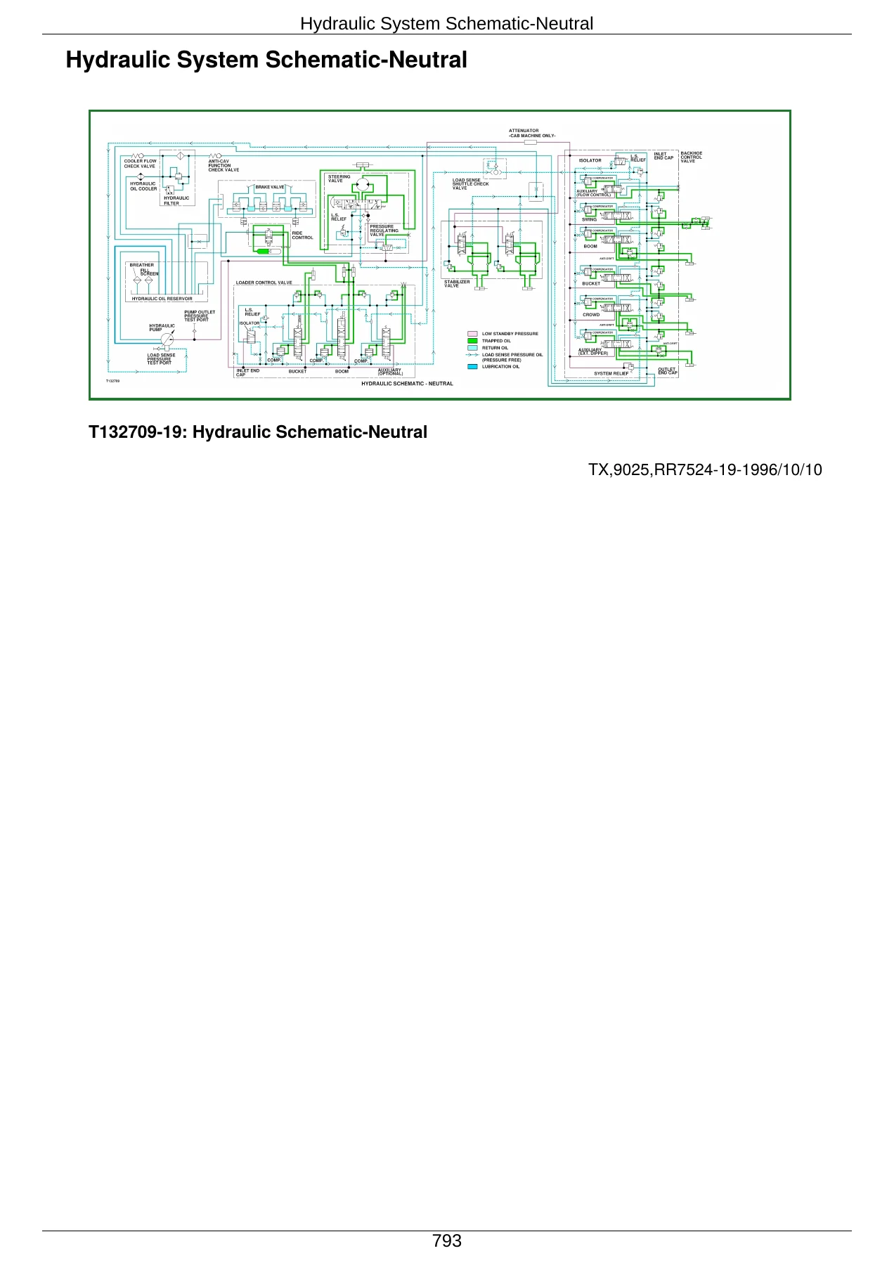
Hydraulic System Schematic-Neutral
Hydraulic System Schematic-Multiple Functions Activated
Hydraulic System Schematic-Neutral with Power Boost MICO Brake Valve
Hydraulic System Schematic-Multiple Functions Activated with Power Boost MICO Brake Valve
Hydrualic Component Location-Power Boost MICO Brake Valve Circuit- Both Pedals Applied
Load Sense Isolatorp. 174
Load Sense With All Functions in Neutral
Load Sense With One Function Activatedp. 175
Load Sense With Multiple Functions Activated
Load Sense With Multiple Functions Activated (One Function Stalled)
Hydraulic Pump-Neutral Operation
Hydraulic Pump-Full Stroke
Hydraulic Pump Controls-Neutral
Hydraulic Pump Controls-Function Metering
Hydraulic Pump Controls-Full Flow
Hydraulic Pump Controls-Flow Limited (High Pressure)
Hydraulic Filter Operation
Steering-No Steering
Steering
Secondary Steering
Ride Control Hydraulic Component Location Circuit-Off
Ride Control Valve Operation “OFF” Position-Continuedp. 180
Ride Control Hydraulic Component Location Circuit-On Position
Ride Control Valve Operation “ON” Position-Continued
Circuit Relief Valve without Anti-Cavitation-Loader and Backhoe
Circuit Relief Valve with Anti-Cavitation-Loader and Backhoe-Continued
Circuit Relief Valve with Anti-Cavitation-Loader and Backhoe (Continued)
Backhoe Auxiliary Flow Control Circuit Relief Valve
Stabilizer Valve Operationp. 183
Backhoe Inlet Section with Swing Section Activated
Backhoe Auxiliary Flow Valve-Solenoid Energized
Backhoe Swing Section-Swing Right Position
Backhoe Boom Section-Boom Raise Position
Backhoe Bucket Section-Bucket Curl Positionp. 185
Backhoe Crowd Section-Crowd In Position
Backhoe Auxiliary Section-Neutral
Backhoe Endcap Outlet Section
Loader Inlet Endcap Section with Bucket Section Activated
Loader Bucket Section-Bucket Rollback Position
Loader Boom Section-Boom Raise Position
Loader Auxiliary Section-Load Position
Loader Endcap Outlet Section
Use These Seven Basic Steps to Diagnose and Test the Hydraulic System
Use These Seven Basic Steps to Diagnose and Test the Hydraulic System
Make a Pretest Inspection and an Operation Check of the Machine
Hydraulic System Pretest
Diagnose Steering System Malfunctionsp. 187
Diagnose Hydraulic System Problems
Loader Bucket Self-Leveling Linkage Indicator and Return-to-Dig Switch Adjustment
Loader Bucket Self-Leveling Linkage Indicator and Return-to-Dig Switch Adjustment
Loader Control Valve Linkage Adjustment
Backhoe Valve Linkage Adjustment
Stabilizer Valve Linkage Adjustmentp. 193
Pre-Test Diagnostics
Pre-Test Diagnostics
Diagnostics Flow Charts
JT05801 Clamp-On Electronic Tachometer Installationp. 194
JT05800 Digital Thermometer Installation
Hydraulic Oil Warm-Up Procedure
Pump Load Sense Differential Pressure Test
Pump Flow Test
Backhoe Load Sense and Loader Load Sense Relief Stall Pressure Test
Steering Load Sense Relief Valve Stall Pressure Test
Flow Limiter Test
Hydraulic Oil Cooler Restriction Test
Circuit Relief Valve Test with Remote Pump
Charging the Ride Control Accumulator
Charging the Ride Control Accumulator-Procedure “A” (14.2 in. accumulator)
Charging the Ride Control Accumulator-Procedure “B” (17.2 in. accumulator)
Ride Control Accumulator Discharge Procedurep. 201
Steering System Leakage Test
Steering Cylinder Leakage Testp. 202
Hydraulic Cylinder Drift Test Procedure
Function Drift Test
Cylinder Leakage Test
Stabilizer Valve Lockout Leakage Testp. 204
Cycle Time Specifications-410E
Proper Refrigerant Handling
Proper Refrigerant Handling
Proper Refrigerant Handling
R134A Refrigerant Cautionsp. 205
Refrigerant Theory Of Operation
Air Conditioning Circuit Operational Information
+Air Conditioning Circuit Theory Of Operation
Low Pressure Switch
High Pressure Switch
A/C Freeze Switch
Air Conditioning Circuit Schematicp. 206
Blower Circuit Operational Information
Blower Circuit Theory Of Operation
Blower Circuit Schematic
Receiver/Dryer Operation
Expansion Valve Operation
Compressor Relief Valve Operation
Temperature Control
Air Conditioning Operational Checks
Air Conditioning Operational Checks
Diagnose Air Conditioning Electrical Malfunctions
Diagnose Air Conditioning Electrical Malfunctions
Air Conditioning Component Location
Special or Essential Tools
Special or Essential Toolsp. 215
Service Equipment and Tools
Other Materials
Proper Refrigerant Handling
R134A Refrigerant Cautions
R134A Compressor Oil Charge Check
R134A Compressor Oil Removalp. 216
R134A Component Oil Charge
R134A Refrigerant Recovery, Recycling And Charging Station Installation Procedure
Recover R134A Systemp. 217
Evacuate R134A System
Charge R134A System
Special or Essential Tools
Special or Essential Tools
Service Equipment and Tools
Proper Refrigerant Handlingp. 219
R134A Refrigerant Cautions
R134A Air Conditioning System Test
Pressure Diagnostic Chart
Low Pressure Switch Test
High Pressure Switch Test
A/C Freeze Control Switch
Leak Testing
Refrigerant Hoses And Tubing Inspection


Reviews
There are no reviews yet.