
John Deere 450 P Crawler Dozer Repair Manual TM14628X019 – PDF Service Guide
Original price was: $39.95.$23.95Current price is: $23.95.
Complete John Deere 450 P Crawler Dozer repair manual TM14628X019 in PDF — 402 pages covering engine, hydrostatic transmission, hydraulics, undercarriage, electrical, blade, ripper, and full torque specifications for PIN DX01837 and up.
Description
This John Deere 450 P Crawler Dozer Repair Manual — document number TM14628X019, published 06MAY24 — is the complete technical service reference for the 450 P crawler dozer from PIN DX01837 onward. At just over 400 pages, it covers every major machine system: undercarriage and track assembly, hydrostatic transmission and final drives, the John Deere diesel engine, main hydraulic system, electrical system, operator station, bulldozer blade, ripper, and all supporting structures. If you service, repair, or rebuild a 450 P crawler dozer, this John Deere 450 P repair manual provides the procedures, specifications, and assembly details required to do the job correctly.
File Details
- Manual Type: Repair / Technical Service Manual
- Brand: John Deere
- Model: 450 P Crawler Dozer
- Document Number: TM14628X019
- Publication Date: 06MAY24 (May 6, 2024)
- Serial Number Break: PIN DX01837— and up
- Language: English
- Page Count: 402 pages
- File Format: PDF
Chapters Covered in This John Deere 450 P Repair Manual
- Group 0001 — Safety Information: Recognise safety information, follow safety instructions, operate only if qualified, wear protective equipment, avoid high-pressure oils and fluids, work in ventilated area, prevent fires, handle chemical products safely, prepare for emergencies, and all remaining safety guidance for the 450 P.
- Group 0002 — General Specifications: Trademarks and general specification data.
- Group 0003 — Torque Values: Metric bolt and cap screw torque, additional metric cap screw torque, unified inch bolt and cap screw torque, service recommendations for 37° flare and 30° cone seat connectors, O-ring boss fittings, O-ring boss fittings in aluminium housings, flared connections (straight and tapered threads), flat face O-ring seal fittings, O-ring face seal fittings with SAE inch hex nut and stud end for high pressure, O-ring face seal fittings with metric hex nut and stud end for standard and high pressure, metric series and inch series four bolt flange fittings, non-restricted banjo (adjustable) fittings, O-ring boss fittings with shoulder, and metric 24° O-ring seal DIN 20078.
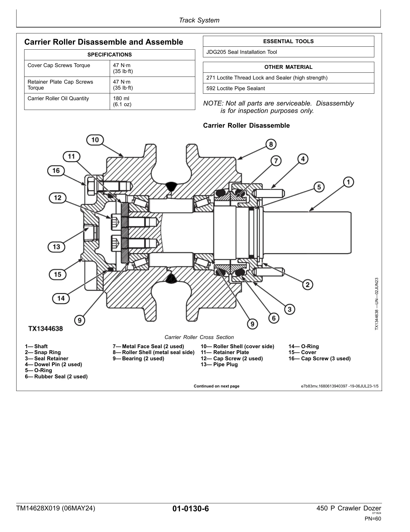
- Section 01 — Tracks (Group 0130 — Track System): Track guides and rock guards removal and installation, carrier roller wear inspection, carrier roller removal and installation, carrier roller disassembly and assembly, metal face seals inspection, carrier roller leakage test, track roller wear inspection, track roller removal and installation, track roller disassembly and assembly, track roller leakage test, track shoe grouser wear inspection, track shoe removal and installation, track link height inspection, bushing outside diameter inspection, track pitch inspection, lubricated track chain removal and installation, turning bushings and lubricating chain, turning pins and bushings without lubricating, track sag adjustment, front idler wear inspection, front idler removal and installation, front idler disassembly and assembly, front idler adjustment, front idler oil level check, track tension adjuster repair, track idler recoil spring removal and installation, track idler recoil spring disassembly and assembly, track frame removal and installation, frame wear strips removal and installation, and sprocket removal and installation.
- Section 02 — Axles and Suspension Systems: Drive axle housing and support (final drive removal and installation), axle shaft, bearings, and reduction gears (final drive disassembly and assembly).
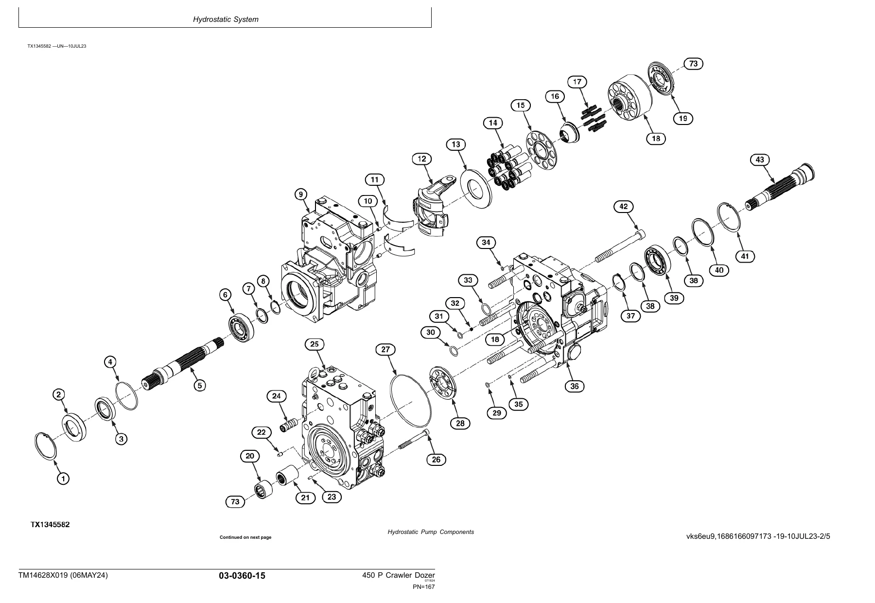
- Section 03 — Transmission: Removal and installation (hydrostatic pump and motor initial start-up procedure, hydrostatic pump removal and installation, hydrostatic motor removal and installation, hydrostatic oil reservoir removal and installation), controls linkage (transmission control lever removal and installation, decelerator/brake pedal removal, installation, disassembly, and assembly), input drive shafts and U-joints (damper drive removal and installation with and without winch), and hydrostatic system (hydraulic component failure cleanup, hydrostatic pump disassembly and assembly with and without winch, metal face seal inspection, charge pump disassembly and assembly, multi-function valve removal and installation, neutral charge relief valve disassembly and assembly, hydrostatic motor disassembly and assembly, hydrostatic thermal bypass valve removal and installation, hydrostatic charge oil filter assembly removal and installation).
- Section 04 — Engine: Engine removal and installation and references to John Deere engine component technical manuals.
- Section 05 — Engine Auxiliary System: Cold weather starting aids (engine coolant heater removal and installation), cooling systems (fan blade removal and installation, cooling package removal, installation, disassembly, and assembly), intake system (air cleaner and precleaner removal and installation), external exhaust systems (exhaust tube removal and installation), and external fuel supply systems (primary fuel filter and water separator removal and installation, secondary fuel filter removal and installation, severe duty fuel filter and water separator, fuel tank removal and installation).
- Section 11 — Park Brake: Park brake removal and installation, park brake valve removal and installation, park brake disassembly and assembly, and park brake valve disassembly and assembly.
- Section 15 — Equipment Attaching: Rigid drawbar removal and installation and extended rigid drawbar removal and installation.
- Section 16 — Electrical System: Right-hand joystick removal, installation, disassembly, and assembly, left-hand joystick removal, installation, disassembly, and assembly, auxiliary control lever removal and installation, rotary sensor removal and installation, air conditioner freeze control switch removal and installation, controller removal and installation, and connector repair information for all connectors used on the machine.
- Section 17 — Frame, Chassis, or Supporting Structure: Welding repair of major structures, bottom guards removal and installation, front counterweight removal and installation, and rear counterweight removal and installation.
- Section 18 — Operator’s Station: Operator’s station removal and installation, operator enclosure (windowpanes, headliner, window wiper motor, window washer pumps, standard primary display unit, primary display unit), seat and seat belt (air suspension seat, replacing seat belt), and heating and air conditioning (R134a refrigerant handling, oil information, recovery and charging station installation, recovery, flushing and purging, evacuation, charging, evaporator or heater core removal and installation, expansion valve, blower motor, heater disassembly and assembly, under-seat heater, receiver-dryer, condenser, and compressor).
- Section 19 — Sheet Metal and Styling: Hood removal and installation, engine side shields removal and installation, rear sheet metal removal and installation, and grille removal and installation.
- Section 20 — Safety, Convenience, and Miscellaneous: Horn and warning devices (backup alarm removal and installation).
- Section 21 — Main Hydraulic System: General oil cleanup procedure, hydraulic component failure cleanup procedure, hydraulic pump removal and installation with and without winch, hydraulic pump disassembly and assembly, hydraulic oil reservoir removal and installation, hydraulic reservoir cleanout cover removal and installation, hydraulic control valve removal and installation (standard and EH), hydraulic control valve disassembly and assembly (standard and EH), and wiper seals and lip seals replacement.
- Section 32 — Bulldozer: Blades (cutting edges and end bits removal and installation, blade removal and installation), control linkage (blade control lever linkage, auxiliary control linkage), frames (C-frame removal and installation), and hydraulic system (cylinder removal and installation, hydraulic cylinder repair).
- Section 42 — Ground Conditioning Tool: Ripper removal and installation, blades, teeth, and shanks (shank and tooth removal and installation), and hydraulic system (ripper cylinder removal and installation).
- Section 99 — Dealer Fabricated Tools: DF1041 track nut removal tool, DF1063 lift bracket, DFT1087 track recoil spring disassembly and assembly guard tool, DFT1119 pump support, DFT1130 adapter, DFT1132 hydrostatic motor/hydraulic pump tool, DFT1137 hydrostatic motor removal and installation tool, DFT1166 final drive lifting bracket adapter, DFT1167 final drive lifting bracket adapter spacer, DFT1211 final drive lifting bracket adapter, DFT1278 30 mm wrench with 3/4-in drive, and ST4920 track recoil spring disassembly and assembly tool.
Taken together, these chapters give a technician a single, organised reference for every service task on the 450 P crawler dozer. The 402-page John Deere 450 P repair manual moves from general specifications and torque values into system-specific procedures, so you can open the correct section and follow the steps, specifications, and assembly order the machine actually needs. Undercarriage work, hydrostatic repair, hydraulic diagnostics, electrical connector repair, and blade or ripper service are all covered in the same document, which means you are not juggling separate publications to complete a job.
What the 450 P Crawler Dozer Repair Manual Enables You to Do
This manual covers the complete mechanical, hydraulic, and electrical scope of the 450 P. With it you can:
- Inspect, adjust, remove, and rebuild the entire undercarriage — carrier rollers, track rollers, front idler, sprocket, track chain, track shoes, track frame, and recoil spring.
- Remove and install the final drive and disassemble/assemble it to specification, including setting pinion shaft preload and axle shaft end play.
- Remove and install the hydrostatic pump and motor, disassemble the pump and motor, and follow the initial start-up procedure to bleed the hydrostatic circuit after a major repair.
- Service the charge pump, multi-function valve, neutral charge relief valve, hydrostatic thermal bypass valve, and hydrostatic charge oil filter.
- Remove and install the hydraulic pump, hydraulic control valve (standard and electrohydraulic), hydraulic oil reservoir, and cleanout cover, and replace wiper and lip seals on the control valve.
- Remove and install the park brake and park brake valve, and disassemble and assemble both to specification.
- Remove and install the engine and the engine auxiliary components — cooling package, fan blade, air cleaner, precleaner, exhaust tube, fuel filters, and fuel tank.
- Service the operator’s station — seat and seat belt, windowpanes, headliner, wiper motors, display units, and the complete heating and air conditioning system including the compressor, condenser, receiver-dryer, expansion valve, evaporator, and heater core.
- Remove and install the blade, cutting edges, end bits, C-frame, lift, tilt, and angle cylinders, and the ripper and ripper cylinder.
- Use the torque value tables and service recommendations to tighten metric and inch fasteners, hydraulic fittings, and flange connections to the correct figures.
- Identify and repair the electrical connectors used across the machine.
- Fabricate the dealer tools specified in Section 99 to carry out jobs that need the proper support or alignment fixtures.
Every procedure in this John Deere 450 P service manual references the correct specifications, whether that is a torque value, an end-play figure, a pressure setting, a capacity, a clearance, or a wear limit. That is what separates a proper repair from a guess, and it is why the manual is written the way it is — so the numbers you need are on the page in front of you.
Who This 450 P Crawler Dozer Repair Manual Is For
This publication is written for the people who actually work on the machine:
- Heavy equipment technicians carrying out routine service, diagnostics, or full component rebuilds on the 450 P crawler dozer.
- Owners and operators who maintain their own machine and want the correct procedures and specifications rather than guesswork.
- Fleet maintenance teams keeping a 450 P dozer in service and needing a single reference for every system.
- Workshops and rebuilders who need the assembly order, torque values, and service limits for the undercarriage, hydrostatic transmission, final drive, and hydraulic system.
Because the manual is a PDF, you can keep it on a laptop, tablet, or phone in the workshop, print only the pages you need for a job, and search the document for the section you are working on. There is no shipping, no waiting, and no bulky binder taking up bench space.
Get the John Deere 450 P Repair Manual TM14628X019 in PDF
IMAGES PREVIEW
With this John Deere 450 P Crawler Dozer Repair Manual in hand you can service the machine from top to bottom — undercarriage to operator station, engine to blade, hydrostatic pump to ripper cylinder — using the procedures and specifications the machine was built around. Correct torque values, correct end play, correct pressures, and the correct sequence mean fewer comebacks, less downtime, and a machine that runs the way it should. Order the 450 P repair manual today and the PDF is available to download immediately after checkout — no shipping, no delays, ready to use on any device or to print for the workshop.
Reviews
There are no reviews yet.