
John Deere 470GLC Excavator Repair Technical Manual TM12180 2016 – PDF Download
Original price was: $71.95.$44.95Current price is: $44.95.
Complete John Deere 470GLC Excavator Repair Technical Manual TM12180 (10MAR16). 468-page PDF covering engine, hydraulics, tracks, swing system, undercarriage, electrical, A/C and more for PIN 1FF470GX_E470001—. Instant download.
Description
John Deere 470GLC Excavator Repair Technical Manual — TM12180
This is the complete John Deere 470GLC Excavator Repair Technical Manual, publication TM12180, dated 10MAR16 and written for PIN 1FF470GX_E470001— and up. It is the same on-the-job guide John Deere authors for experienced technicians — organised component by component, with the procedures, tolerances, torque values and illustrations needed to diagnose, analyse, test and repair the 470GLC from the tracks to the bucket.
File Details
- Manual Type: Repair Technical Manual
- Brand: John Deere
- Model: 470GLC Excavator
- PIN: 1FF470GX_E470001—
- Publication Number: TM12180
- Date: 10MAR16 (March 2016)
- Language: English
- Page Count: 468
- File Format: PDF
Chapters Covered
- Section 00 — General Information
- Section 01 — Tracks
- Section 02 — Axles and Suspension Systems
- Section 04 — Engine
- Section 05 — Engine Auxiliary System
- Section 07 — Damper Drive (Flex Coupling)
- Section 17 — Frame or Supporting Structure
- Section 18 — Operator’s Station
- Section 19 — Sheet Metal
- Section 33 — Excavator
- Section 43 — Swing System
- Section 99 — Dealer Fabricated Tools
Section 00 — General Information
Opens with the full safety group — safety alert symbols, DANGER/WARNING/CAUTION conventions, protective equipment requirements, high-pressure fluid and oil hazards, welding and paint-removal precautions, battery and exhaust filter handling, decommissioning and fluid disposal. The torque values group then supplies general metric bolt and cap screw torque charts by property class, additional metric cap screw torque tables, and unified inch bolt and cap screw values. A hydraulic fitting section covers straight, angle, O-ring boss, flat-face O-ring seal, four-bolt flange and metric 24° O-ring seal (DIN 20078) service recommendations with fitting-by-fitting torque charts.
Section 01 — Tracks
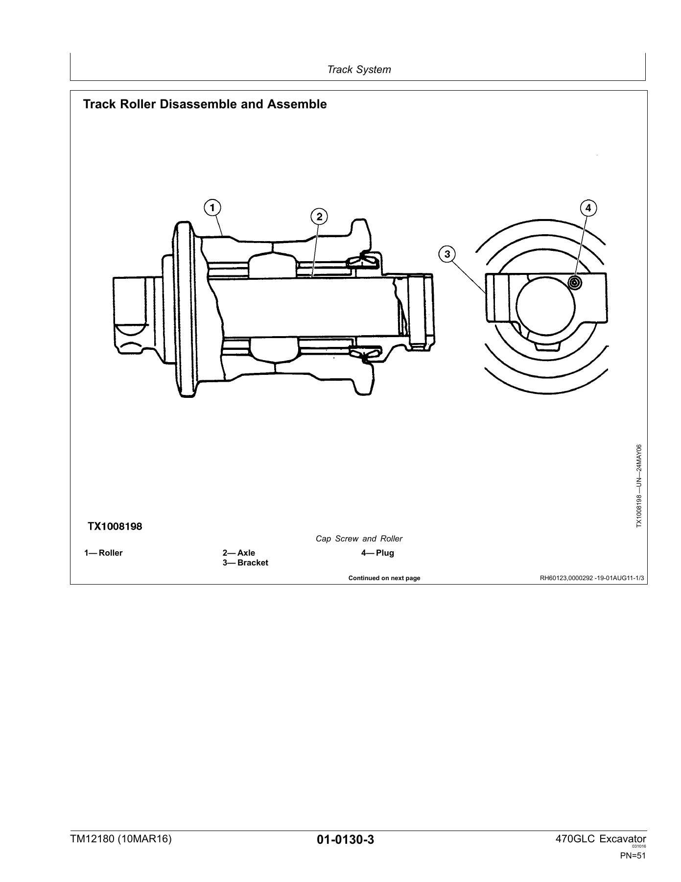
Covers the complete track system: track roller pressure test, track carrier roller removal/installation and disassembly/assembly, metal face seal inspection, track shoe and track chain removal/installation, chain disassembly/assembly, track link repair to replace broken pins or links, sprocket removal/installation, front idler removal/installation, disassembly/assembly and pressure test, track adjuster and recoil spring removal/installation and disassembly/assembly, and track adjuster cylinder work. Includes front idler pin/bushing removal and assembly torque values.
Section 02 — Axles and Suspension Systems
Travel gear case removal/installation and disassembly/assembly (axle shaft, bearings and reduction gears), plus the hydraulic side: travel motor and park brake removal/installation, travel motor and park brake disassembly/assembly, counterbalance valve, crossover relief valves, make-up check valve, travel speed selector valve removal/installation, and the travel motor and park brake start-up procedure.
Section 04 — Engine
Engine removal and installation with the full tagging and disconnection sequence — exhaust filter, intercooler, intake, cooling, fuel, heater and oil lines, starter, alternator, A/C compressor, harness connectors and mounting hardware. Also covers turbocharger removal/installation, starter motor removal/installation, belt removal/installation and alternator removal/installation. Engine itself is the Isuzu 6UZ1 Interim Tier 4 as referenced by the manual.
Section 05 — Engine Auxiliary System
Cooling systems group (radiator, hydraulic oil cooler, intercooler, fuel cooler, complete cooling package, fan shroud and coolant recovery tank), intake system group (air intake system leakage test and air cleaner), external exhaust group (exhaust tube, DPF and exhaust filter removal/installation and disassembly/assembly), and external fuel supply group (fuel tank, primary fuel filter and water separator, final fuel filter and water separator).
Section 07 — Damper Drive (Flex Coupling)
Damper drive (flex coupling) removal and installation, including damper gear, damper and mounting cap screws.
Section 17 — Frame or Supporting Structure
Welding on machine, welding repair of major structure (with preheat temperatures and weld metal specifications), and counterweight removal/installation.
Section 18 — Operator’s Station
Cab removal/installation, windshield removal and disassembly/assembly, sliding windows, window panes and dimensioned glass drawings, seat and seat belt removal/installation, air suspension seat disassembly/assembly, left and right console covers, and the full heating and air conditioning group: refrigerant handling, flush and purge, R134a oil information, recovery/recycling/charging station procedure, recovery, evacuation, charging, compressor and clutch, condenser, heater and A/C, and receiver-dryer.
Section 19 — Sheet Metal
Hood and engine side shields removal/installation and cooling package door removal/installation.
Section 33 — Excavator
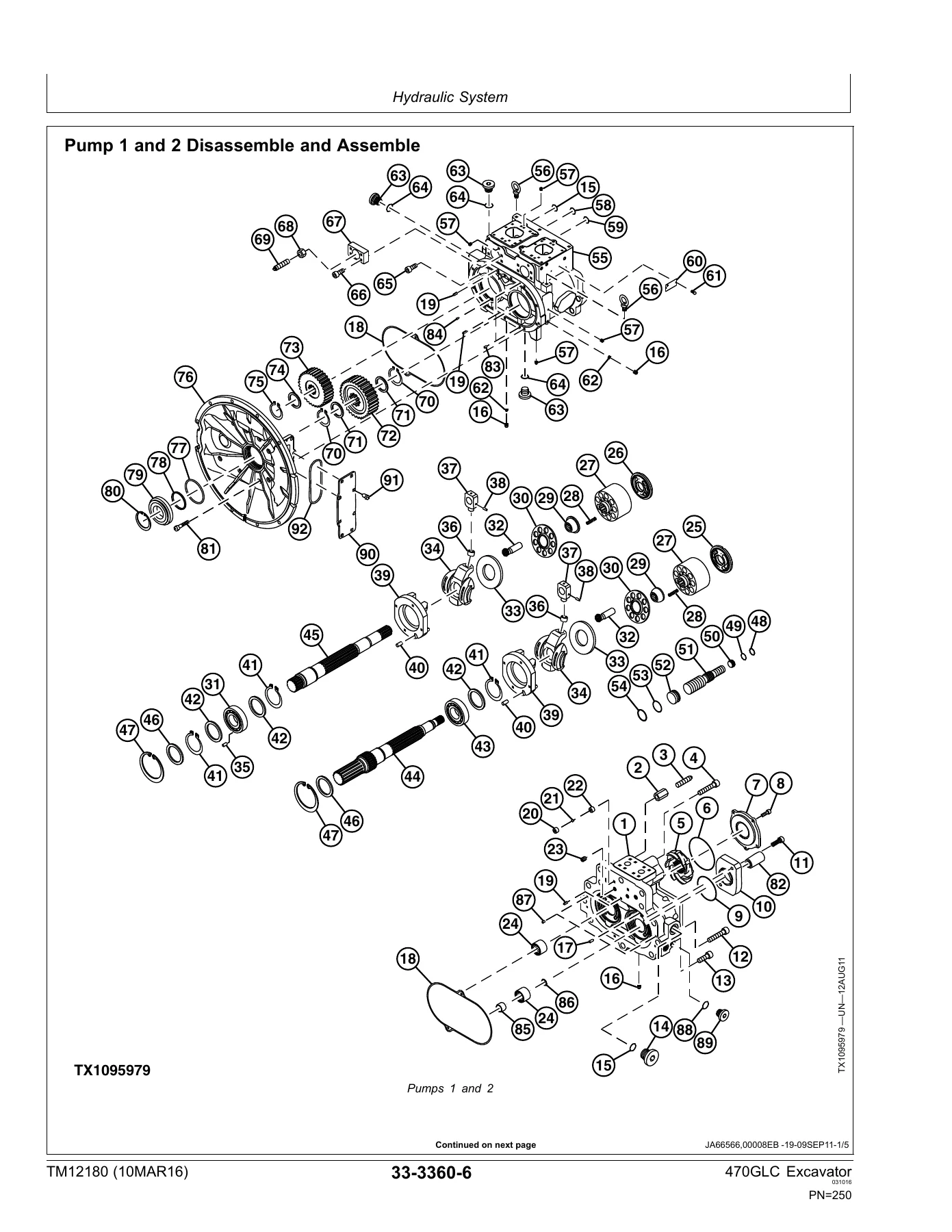
The largest repair section. Buckets and bucket pin-up data; frames group with bucket links, arm, boom, pin/bushing/boss inspection, and bushing and seal removal/installation; hydraulic system group covering vacuum application, circuit pressure release, pumps 1 and 2 removal/installation, disassembly/assembly and inspection, pump 1 and 2 regulator, pilot pump, pilot filter and pressure regulating valve, pilot shutoff solenoid valve, fan drive pump and regulator, fan drive motor, fan drive reversing control valve, fan drive system relief valve, solenoid valve manifolds and solenoids, pump case drain filter and bypass valve, pilot valves, boom up shockless valve, travel pilot control valve, pilot accumulator, pilot check valve manifold, pilot signal manifold, counterweight pilot control valve, counterweight shutoff valve, counterweight check valve, control valve, hydraulic oil tank, hydraulic oil restriction valve, hydraulic oil cooler bypass valve, hydraulic oil cooler, boom cylinder, arm cylinder, bucket cylinder, counterweight cylinder, counterweight removal device, and the hydraulic cylinder bleed procedure.
Section 43 — Swing System
Mechanical drive elements — swing gear case removal/installation, disassembly/assembly and start-up procedure, upperstructure removal/installation, swing bearing removal/installation, disassembly/assembly, upper seal and lower seal install. Hydraulic side — center joint removal/installation, disassembly/assembly and air test, swing motor and park brake removal/installation, disassembly/assembly and start-up procedure, swing motor crossover relief valve, swing motor make-up check valve and swing park release valve.
Section 99 — Dealer Fabricated Tools
Drawings and material lists for the dealer-fabricated tools the manual calls for — DF1063 lift bracket, DFT1130 adapter, center joint (rotary manifold) lifting tool, DFT1119 pump support and DFT1220 swing gear case nut spanner wrench.
What This John Deere 470GLC Repair Manual Lets You Do
Any job on the 470GLC — a track chain rebuild, a travel gear case overhaul, a swing gear case teardown, a boom or arm cylinder reseal, a control valve rebuild, an HVAC service, an exhaust filter or DPF change, an engine or turbocharger pull, a counterweight removal, a torque-and-tolerance check on the front attachment pins and bushings — is laid out step by step in this TM12180 manual. Every procedure is written against real John Deere shop practice: what to support, what to tag, what to release, what to torque to, and what clearances and wear limits are acceptable. That matters on a 49-ton excavator where a wrong torque, a pinched O-ring or an unsupported component is expensive and dangerous. And because it covers both the repair and the operation-and-test side of the 470GLC, it is equally useful for a scheduled service, a mid-shift diagnosis or a full component rebuild.
IMAGES PREVIEW
Delivery is instant. Pay once, download the PDF, and it is yours — no shipping, no waiting on a paper binder. Read it in the cab on a tablet, in the shop on a laptop, or print the pages for the job in front of you.
Reviews
There are no reviews yet.