John Deere 5103, 5203, 5204, 5303, 5403, 5045D, 5045E, 5055D, 5055E, 5065E, 5075E Tractor Technical Manual TM900019
The John Deere 5103, 5203, 5204, 5303, 5403, 5045D, 5045E, 5055D, 5055E, 5065E, 5075E Tractor Technical Manual TM900019 is a large service reference built around repair work, system operation, diagnosis, testing and adjustment for the tractor configurations identified throughout TM900019. Published September 2013, it brings machine specifications, repair procedures, troubleshooting paths, test procedures, adjustment information, wiring information and hydraulic schematics together in one technical manual. Coverage is arranged by system so an experienced technician can move from a symptom or checkout result to the related repair group, specification, test or adjustment.
File Details
- Manual type: Technical Manual
- Brand: John Deere
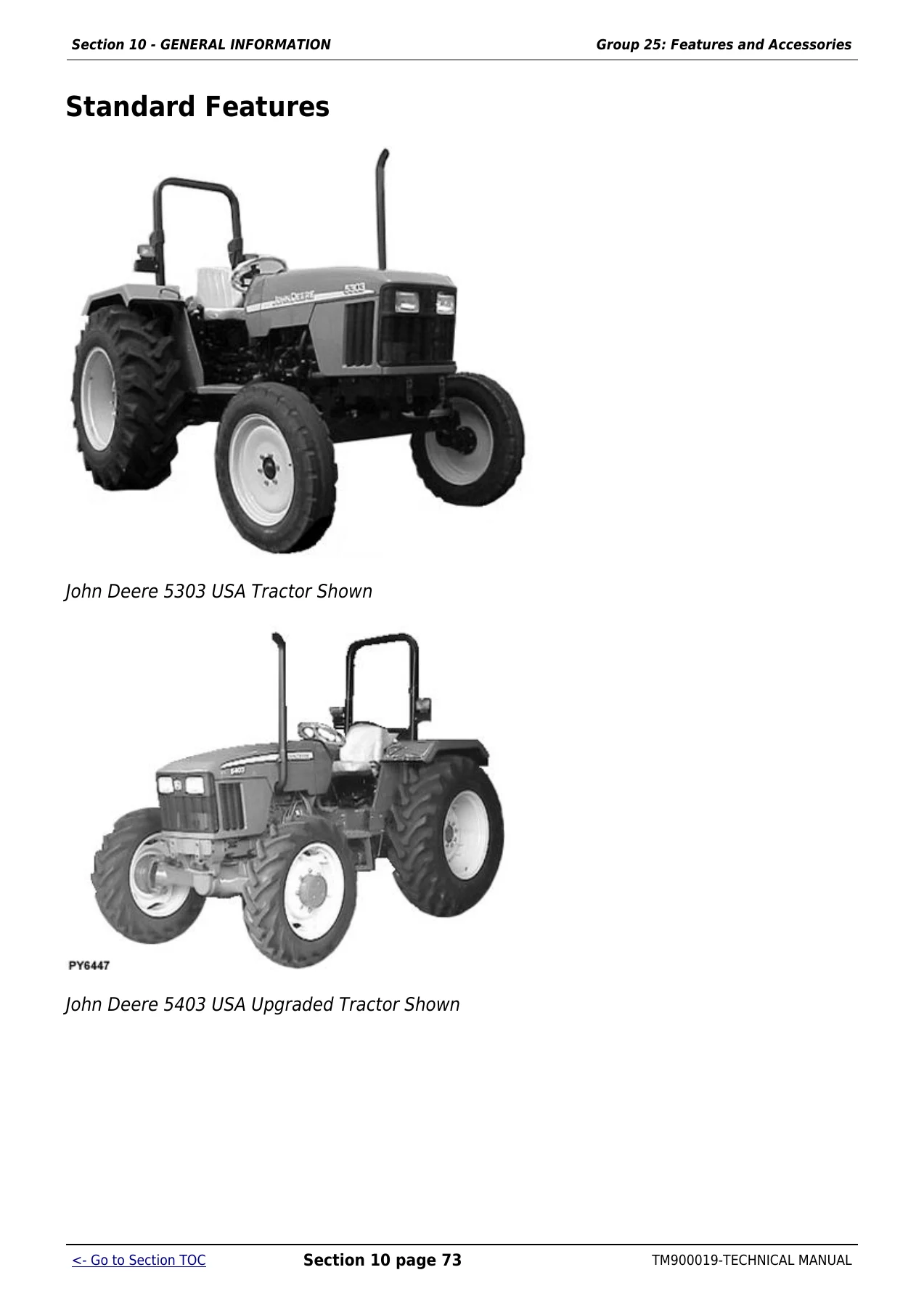
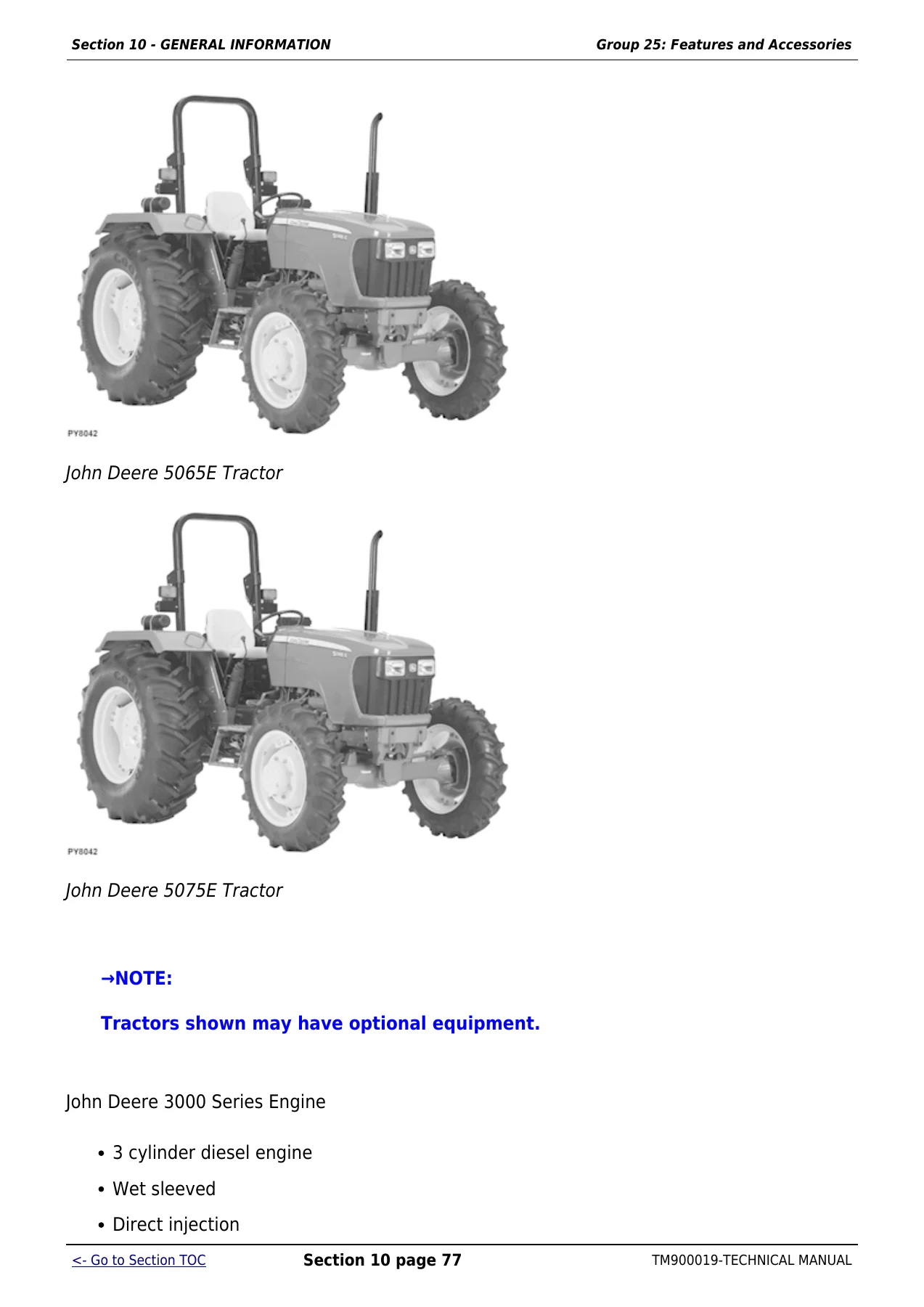
- Models: 5103, 5203, 5204, 5303, 5403, 5045D, 5045E, 5055D, 5055E, 5065E and 5075E
- Document number: TM900019
- Date: September 2013
- Language: English
- Page count: 2365 pages
- File format: PDF
Model and Regional Coverage
TM900019 contains model- and market-specific material rather than treating every tractor as one identical configuration. The title identifies 5103, 5203, 5303, 5403, 5045, 5055, 5065 and 5075 tractors for USA, Mexico and Australia applications, with additional coverage for 5103, 5203, 5303 and 5403 Australia tractors, 5303 and 5403 Latin America tractors, and 5204 and 5303 Mexico tractors. Within the technical sections, the 5045 and 5055 families are separated into 5045D, 5045E, 5055D and 5055E, alongside 5065E and 5075E.
The specifications also distinguish engine and tractor configurations. The manual includes 3029T turbocharged applications, 3029D naturally aspirated applications and a 3029H turbocharged application for the 5075E. USA tractor information records serial starting points for several models, including 5103 from PY5103U013640-, 5203 from PY5203U005569-, 5303 from PY5303U007752- and 5403 from PY5403U000727-. These distinctions matter when using electrical theory, wiring schematics, transmission information, specifications and diagnostics that are tied to a particular market or configuration.
Chapters Covered
- General Information – safety; general specifications; fuel and lubricants; serial number locations; features and accessories
- Engine Repair – engine; cylinder head and valves; cylinder block, liners, pistons and rods; crankshaft, main bearings and flywheel; camshaft and timing gear train; lubrication system; cooling system
- Fuel and Air Repair – fuel system; air intake and exhaust system; speed control linkage
- Electrical Repair – battery, starter and alternator; electrical system components; wiring harness
- Power Train Repair – clutch housing; clutch assembly; ‘S’ transmission; ‘AA’ transmission; rear PTO for both transmission types; differential; final drives; mechanical front wheel drive
- Steering and Brake Repair – steering repair; brake repair for ‘S’ transmission; brake repair for ‘AA’ transmission
- Hydraulic Repair – hydraulic pump and filter; MITA rockshaft; JD rockshaft; MITA selective control valve; EATON selective control valve; mid mount selective control valve
- Miscellaneous Repair – 2WD front axle; wheels; 3-point hitch; hood
- Operator Station Repair – seat and support; center console; Roll-Gard; operator platform; fenders; canopy when equipped
- Operational Checkout Procedures – engine oil and coolant checks; transmission and hydraulic oil; fuel and air intake; electrical and hydraulic checks; engine starting; steering; differential lock; clutch; transmission and range shifting; brakes; rockshaft; selective control valve
- Engine Operation, Tests and Adjustments – component locations; theory of operation; diagnosis, tests and adjustments
- Fuel/Air Operation, Test and Adjustments – component locations; theory of operation; diagnosis, tests and adjustments
- Electrical System Operation, Tests and Adjustments – component locations; regional and model-specific theory of operation; diagnosis, tests and adjustments; wiring schematics; connector information
- Power Train Operation, Tests and Adjustments – transmission component locations; theory of operation; diagnosis, tests and adjustments
- Steering and Brake Operation, Test and Adjustments – component locations; theory of operation; diagnosis, tests and adjustments
- Hydraulic System Operation, Test and Adjustments – component locations; theory of operation; diagnosis; tests without SCV, with SCV and with mid mount control valve; general hydraulic tests; adjustments; hydraulic schematics
Complete PDF Bookmark Tree
Complete Bookmarks
The complete bookmarks in the “John Deere 5103, 5203, 5204, 5303, 5403, 5045D, 5045E, 5055D, 5055E, 5065E, 5075E Tractor Technical Manual TM900019” are as follows:
Table of contentsp. 2
FOREWORDp. 5
+Section 10 – GENERAL INFORMATIONp. 8
+Group 05 – Safetyp. 8
Recognize Safety Informationp. 8
Understand Signal Wordsp. 8
Follow Safety Instructionsp. 9
Handle Fluids Safely—Avoid Firesp. 9
Prevent Battery Explosionsp. 10
Prepare for Emergenciesp. 11
Prevent Acid Burnsp. 12
Service Cooling System Safelyp. 13
Avoid High-Pressure Fluidsp. 13
Park Machine Safelyp. 14
Support Machine Properlyp. 15
Wear Protective Clothingp. 16
Work in Clean Areap. 17
Service Machines Safelyp. 17
Work In Ventilated Areap. 18
Illuminate Work Area Safelyp. 18
Replace Safety Signsp. 19
Use Proper Lifting Equipmentp. 19
Service Tires Safelyp. 20
Avoid Harmful Asbestos Dustp. 22
Avoid Heating Near Pressurized Fluid Linesp. 22
Remove Paint Before Welding or Heatingp. 23
Use Proper Toolsp. 24
Dispose of Waste Properlyp. 25
Live With Safetyp. 25
+Group 10 – General Specificationsp. 27
Machine Specifications (For USA and Australia Tractors)p. 27
Machine Specifications (For USA Tractors)p. 30
Machine Specifications (For Latin America Tractors)p. 35
Machine Specifications (Mexico Tractors)p. 37
Repair Specificationsp. 39
Ground Speed Estimatesp. 44
Service Recommendations for O-Ring Boss Fittingsp. 48
Service Recommendations for Flat Face O-Ring Seal Fittingsp. 51
Metric Bolt and Cap Screw Torque Valuesp. 53
Unified Inch Bolt and Cap Screw Torque Valuesp. 54
+Group 15 – Fuel and Lubricantsp. 55
Diesel Fuelp. 55
Biodiesel Fuelp. 57
Handling and Storing Diesel Fuelp. 59
Fuel Storagep. 60
Do Not Use Galvanized Containersp. 61
Fill Fuel Tankp. 62
Diesel Engine Oilp. 64
Heavy Duty Diesel Engine Coolantp. 66
Transmission and Hydraulic Oilp. 68
Grease (Specific Application)p. 69
Greasep. 69
Alternative and Synthetic Lubricantsp. 70
Lubricant Storagep. 70
+Group 20 – Serial Number Locationsp. 71
Serial Numbersp. 71
Product Identification Number Locationp. 71
Engine Serial Number Locationp. 71
Fuel Injection Pump Serial Number Locationp. 72
Alternator Serial Number Locationp. 73
Power Steering Valve Serial Number Locationp. 73
Starter Serial Number Locationp. 74
Transmission Serial Number Locationp. 75
Front Axle Serial Number Location (2WD)p. 76
Front Axle Serial Number Location (MFWD)p. 76
+Group 25 – Features and Accessoriesp. 78
Features and Accessoriesp. 78
Standard Featuresp. 79
Factory Installed Optional Equipmentp. 85
Field Installed Optional Kits and Accessoriesp. 85
+Section 20 – ENGINE REPAIRp. 91
+Group 05 – Enginep. 91
Service Equipment and Toolsp. 91
Specificationsp. 91
John Deere Engine Repair—Use CTM8p. 91
Remove Enginep. 92
Install Enginep. 102
Engine Disassembly Sequencep. 113
Sealant Application Guidelinesp. 116
Engine Re-Assembly Sequencep. 117
Engine Break-In Guidelinesp. 119
Perform Engine Break-Inp. 120
Diesel Engine Break-In Oilp. 120
+Group 10 – Cylinder Head and Valvesp. 122
Special or Essential Toolsp. 122
Specificationsp. 123
Torques for Hardwarep. 124
Cylinder Head – Exploded Viewp. 124
Check Valve Liftp. 126
Remove Cylinder Headp. 128
Clean Injection Nozzle Boresp. 131
Valve Actuating Partsp. 132
Remove Valves and Valve Springsp. 132
Checking Cylinder Head Flatnessp. 134
Clean Valve Guidesp. 134
Measure Valve Guidesp. 136
Knurl Valve Guidesp. 138
Clean and Inspect Valve Seatsp. 138
Lapping Valve Seatsp. 139
Check Valve Recessp. 140
Remove Valve Seat Insertsp. 142
Valve Seat Insert Installationp. 145
Check Valvesp. 146
Grind Valvesp. 147
Check Valve Spring Compressionp. 147
Inspect Valve Rotatorsp. 147
Install Valvesp. 149
Install Cylinder Headp. 151
Torque Turn Tightening Methodp. 154
Disassembling and Checking Rocker Arm Shaftp. 156
Reassembling Rocker Arm Shaftp. 158
Install Rocker Arm Assemblyp. 159
Valve Clearancep. 160
Valve Adjustment Sequencep. 162
Install Rocker Arm Coverp. 163
Final Workp. 164
+Group 15 – Cyl. Block, Liners, Pistons & Rodsp. 166
Special or Essential Toolsp. 166
Specificationsp. 167
Torques for Hardwarep. 168
Exploded Viewp. 168
Connecting Rods – General Informationp. 170
Remove Pistons and Connecting Rodsp. 172
Measure Cylinder Liner Borep. 175
Remove Cylinder Linersp. 176
Cylinder Liner Deglazingp. 178
Cylinder Block Cleaningp. 178
Check Piston Cooling Jetsp. 179
Cam Follower Bore Measurep. 180
Measure Camshaft Borep. 181
Remove Camshaft Bushingp. 182
Install Camshaft Bushingp. 184
Measure Crankshaft Borep. 185
Replace Crankshaft Bearing Capsp. 186
Cylinder Block Top Desk Flatnessp. 187
Measure Cylinder Liner Protrusionp. 188
Liner Packing Installationp. 190
Liner O-Ring Installationp. 190
Install Cylinder Linersp. 192
Measure Connecting Rod Bearingp. 194
Rod Bearing Clearancep. 195
Measure Connecting Rod Bushingp. 196
Replace Connecting Rod Bushing (3029D)p. 196
Replace Connecting Rod Bushing (3029T)p. 198
Measure Piston Pinp. 201
Clean and Inspect Pistonsp. 202
Measure Piston Pin Borep. 202
Piston Top Ring Groovep. 203
Second and Third Piston Ring Groovesp. 204
Piston Head and Skirt Checkingp. 205
Install Piston Ringsp. 206
Piston Rings Staggeringp. 207
Piston/Liner Set Informationp. 208
Assemble Piston and Connecting Rodp. 210
Install Piston and Connecting Rodp. 212
Measure Piston Protrusionp. 217
Complete Final Assemblyp. 219
+Group 20 – Crankshaft, Main Bearings and Flywheelp. 223
Special or Essential Toolsp. 223
Specificationsp. 224
Torques For Hardwarep. 225
Remove Crankshaft Pulleyp. 225
Install Crankshaft Pulleyp. 225
Flywheel Removalp. 226
Flywheel Ring Gear Replacementp. 228
Install Ball Bearingp. 229
Install Flywheelp. 229
Remove Crankshaft Rear Oil Sealp. 231
Flywheel Housing Replacement (′S′ Transmission)p. 236
Flywheel Housing Replacement (′AA′ Transmission)p. 238
Install Oil Seal/Wear Sleevep. 240
Crankshaft End Play Measurep. 242
Remove Crankshaftp. 243
Crankshaft Inspectionp. 243
Check Crankshaft Journal Diameterp. 245
Determine Crankshaft Main Bearing Clearance Using PLASTIGAGE PLASTIGAGE is a trademark of DANA Corp.p. 247
Regrind Crankshaftp. 247
Crankshaft Regrinding Guidelinesp. 249
Micro-Finishing Specificationsp. 250
Replace Crankshaft Gearp. 251
Install Main Bearing Insertsp. 252
Install 2-Piece Thrust Bearingp. 252
Crankshaft Installationp. 254
+Group 25 – Camshaft and Timing Gear Trainp. 256
Special or Essential Toolsp. 256
Specificationsp. 257
Torques for Hardwarep. 258
Remove Crankshaft Front Oil Sealp. 259
Remove Timing Gear Coverp. 259
Measure Timing Gear Backlashp. 261
Camshaft End Play Measurep. 262
Remove Camshaftp. 263
Measure Camshaft Journalp. 264
Measure Height of Cam Lobep. 264
Replace Camshaft Gearp. 265
Install Camshaftp. 267
Check Cam Followerp. 267
Idler Gear End Play Measurep. 268
Remove Front Platep. 270
Idler Gear Bushing and Shaft Measurep. 272
Idler Gear Bushing Replacementp. 274
Remove Idler Shaftp. 274
Install Idler Shaft Spring Pinp. 276
Install Idler Shaftsp. 278
Install Front Platep. 280
Install Upper Timing Gear Trainp. 283
Install Lower Timing Gear Trainp. 286
Install Oil Deflectorp. 286
Timing Gear Cover Identificationp. 287
Install Timing Gear Coverp. 288
Install Crankshaft Front Oil Sealp. 290
Install Wear Ringp. 291
Install Auxiliary Equipmentp. 292
+Group 30 – Lubrication Systemp. 294
Special or Essential Toolsp. 294
Specificationsp. 295
Torques for Hardwarep. 296
Oil Cooler Identificationp. 296
Remove Oil Coolerp. 296
Replace Oil Cooler Nipplep. 298
Install Oil Coolerp. 298
Replace Oil Cooler/Filter Bracket on Engine with Auxiliary Drivep. 300
Remove Oil Pressure Regulating Valvep. 301
Replace Oil Pressure Regulating Valve Seatp. 302
Install Oil Pressure Regulating Valvep. 302
Replace Oil Dipstick Guidep. 303
Replace Oil By-Pass Valvep. 304
Replace Oil Pump Strainerp. 305
Remove Oil Pumpp. 306
Oil Pump Gear Axial Clearancep. 307
Oil Pump Gear Radial Clearancep. 307
Oil Pump Specificationsp. 309
Oil Pump Installationp. 310
Install Oil Panp. 314
+Group 35 – Cooling Systemp. 316
Special or Essential Toolsp. 316
Specificationsp. 316
Torques for Hardwarep. 317
Remove and Inspect Radiatorp. 318
Remove and Inspect Radiator(5045D, 5045E, 5055D, 5055E, 5065E and 5075E Tractors)p. 324
Water Pump — Exploded Viewp. 329
Remove Water Pumpp. 330
Disassemble Water Pumpp. 331
Assemble Water Pumpp. 334
Install Water Pumpp. 338
Inspect Thermostatp. 339
Cooling System Deaerationp. 340
Check Fan/Alternator Belt Tensionp. 342
Install Fanp. 345
Install Radiatorp. 347
Install Radiator(5045D, 5045E, 5055D, 5055E, 5065E and 5075E Tractors)p. 350
Replace Thermostatp. 355
+Section 30 – FUEL AND AIR REPAIRp. 360
+Group 05 – Fuel Systemp. 360
Special or Essential Toolsp. 360
Injection Pump, Nozzle and Governor Repair—Use CTM8p. 360
Remove, Inspect and Install Fuel Tankp. 362
Replace Fuel Filterp. 365
Replace Fuel Filter/Primer Pump Assemblyp. 368
Remove Fuel Injection Pumpp. 370
Repairs to Fuel Injection Pumpp. 373
Replace Throttle Leverp. 373
Install Fuel Injection Pumpp. 375
Remove Fuel Injection Nozzlep. 378
Clean Fuel Injection Nozzlep. 379
Fuel Injection Nozzle Disassemblyp. 380
Install Fuel Injection Nozzlep. 381
+Group 10 – Air Intake and Exhaust Systemp. 384
Remove, Inspect, and Install Air Cleaner Elementsp. 384
Check Air Inlet Pipep. 387
Check Air Inlet Pipe with Turbocharger (If Equipped)p. 388
Exhaust Manifold Inspection (If Equipped)p. 389
Remove Turbocharger (If Equipped)p. 389
Turbocharger Cut-Away View (Borge Warner) – (If Equipped)p. 390
Check Radial Clearancep. 392
Check Axial Clearancep. 392
Repair Turbocharger (If Equipped)p. 393
Prelube Turbocharger (If Equipped)p. 393
Install Turbocharger (If Equipped)p. 395
Turbocharger Break-In (If Equipped)p. 397
Recommendations for Turbocharger Use (If Equipped)p. 398
+Group 15 – Speed Control Linkagep. 399
Inspect and Repair Speed Control Linkagep. 399
+Section 40 – ELECTRICAL REPAIRp. 402
+Group 05 – Battery, Starter and Alternatorp. 402
Starter Repair—Use CTM77p. 402
Remove and Install Batteryp. 403
Remove and Install Starterp. 405
Replace Alternator/Regulatorp. 407
+Group 10 – Electrical System Componentsp. 409
Service Equipment and Toolsp. 409
Other Materialp. 409
Replace Air Filter Restriction Sensorp. 410
Replace Coolant Temperature Senderp. 412
Replace Engine Speed Sensorp. 413
Replace Engine Oil Pressure Sensorp. 414
Replace Key Switchp. 415
Replace Light Switchp. 417
Replace Turn Signal Controllerp. 419
Replace Instrument Panelp. 421
Replace Rear PTO Switch (If Equipped)p. 424
Remove and Install Rear PTO Switch-For 5045E, 5055E, 5065E and 5075E Tracatorsp. 426
Replace Park Position Start Switchp. 436
Replace Seat Switch (If Equipped)p. 438
Replace Fuel Level Senderp. 441
+Group 15 – Wiring Harnessp. 443
Special or Essential Toolsp. 443
Service Parts Kitsp. 443
Remove Connector Body from Blade Terminalsp. 443
Replace WEATHER PACK WEATHER PACK is a trademark of Packard Electric. Connectorp. 444
Install WEATHER PACK WEATHER PACK is a trademark of Packard Electric. Contactp. 446
Replace Tractor Wiring Harnessp. 448
Replace Tractor Wiring Harness (5204 Mexico Tractor)p. 451
+Section 50 – POWER TRAIN REPAIRp. 460
+Group 05 – Clutch Housingp. 460
Service Equipment and Toolsp. 460
Other Materialp. 460
Specificationsp. 460
Separate Engine from Clutch Housingp. 461
Install Engine to Clutch Housingp. 470
Replace Clutch Housing Seal (′S′ Transmission)p. 479
Inspect and Repair Clutch Pedal and Linkage (′S′ Transmission)p. 482
Inspect and Repair Clutch Pedal and Linkage (′AA′ Transmission)p. 484
+Group 10 – Clutch Assemblyp. 486
Essential Toolsp. 486
Service Equipment and Toolsp. 486
Other Materialp. 486
Specificationsp. 487
Remove and Install Clutch Assemblyp. 488
Disassemble and Inspect Clutch Assemblyp. 493
Assemble Clutch Assemblyp. 506
Traction Clutch Finger Adjustmentp. 514
PTO Clutch Finger Adjustmentp. 517
Remove and Inspect Clutch Release Mechanism and Shaftsp. 520
Install Clutch Release Mechanism and Shaftsp. 526
+Group 15 – ′S′ Transmissionp. 531
Specificationsp. 531
Separate Clutch Housing From Transmissionp. 532
Install Clutch Housing to Transmissionp. 538
Inspect and Repair Gear Shift Leversp. 544
Inspect and Repair Gear Shift Lever (For 5045E, 5055E, 5065E and 5075E Tractors)p. 547
Inspect and Repair Range Shift Leverp. 549
Inspect and Repair Range Shift Lever (For 5045E, 5055E, 5065E and 5075E Tractors)p. 552
Remove Transmissionp. 554
Disassemble and Inspect Transmission— Collarshiftp. 562
Assemble Transmission — Collarshiftp. 572
Disassemble and Inspect Transmission — SyncShuttle™p. 581
Assemble Transmission — SyncShuttle™p. 591
Install Transmissionp. 599
Disassemble, Inspect and Assemble Gear Shift Shaft Assembliesp. 605
Disassemble, Inspect, and Assemble CollarShift Transmission Top Shaftp. 608
Disassemble, Inspect, and Assemble SyncShuttle™ Transmission Top Shaft— For Australia Tractorsp. 611
Disassemble, Inspect, and Assemble SyncShuttle™ Transmission Top Shaft—For USA Tractorsp. 614
Disassemble, Inspect, and Assemble Transmission Top Shaft—Partial SyncShuttle™ Transmissionp. 618
Disassemble, Inspect, and Assemble Range Reduction Shaftp. 622
Disassemble, Inspect and Assemble Driven Shaftp. 624
Remove, Inspect, and Install Range Gearsp. 626
Remove, Inspect, and Install Reverse Idler Shaftp. 628
+Group 20 – ′AA′ Transmissionp. 631
Other Materialp. 631
Specificationsp. 631
Remove, Inspect and Repair Gear Shift Lever And Coverp. 632
Remove, Inspect and Repair Gear Shift Lever And Cover (For 5045D and 5055D Tractors)p. 635
Remove, Inspect and Install Range and Reverse Shift Leverp. 638
Remove, Inspect and Install Range and Reverse Shift Lever (For 5045D and 5055D Tractors)p. 642
Remove Transmissionp. 646
Disassemble and Inspect Transmissionp. 649
Assemble Transmissionp. 656
Install Transmissionp. 664
Disassemble, Inspect and Assemble Shift Shaft Assembliesp. 667
Disassemble, Inspect, and Assemble Transmission Main Shaftp. 670
Disassemble, Inspect and Assemble Range Reduction Shaftp. 672
Disassemble, Inspect and Assemble Driven Shaftp. 675
Disassemble, Inspect and Assemble Traction Clutch Driven Shaftp. 678
+Group 21 – Rear PTO (′S′ Transmission)p. 680
Other Materialp. 680
Specificationsp. 680
Remove, Inspect and Install Rear PTO Lever and Linkagep. 681
Remove, Inspect and Install Rear PTO Lever and Linkage – Cable Linkagep. 684
Remove, Inspect and Install Rear PTO Lever and Linkage – Cable Linkage – For 5045E, 5055E, 5065E and 5075E Tractorsp. 686
Remove and Install Standard Rear PTO Drive Shaft Assemblyp. 688
Disassemble, Inspect and Assemble Standard Rear PTO Drive Shaft Assemblyp. 690
+Group 25 – Rear PTO (′AA′ Transmission)p. 693
Other Materialp. 693
Specificationsp. 693
Remove, Inspect and Install Rear PTO Lever and Linkagep. 694
Remove, Inspect and Install Rear PTO Lever and Linkage – For 5045D and 5055D Tractorsp. 699
Remove and Install Rear PTO Drive Shaft Assemblyp. 704
Disassemble, Inspect and Assemble Rear PTO Drive Shaft Assemblyp. 707
Disassemble, Inspect and Assemble Rear PTO Drive Shaft Assemblyp. 710
+Group 26 – Differentialp. 713
Essential Toolsp. 713
Service Equipment and Toolsp. 713
Other Materialp. 713
Specificationsp. 714
Service Parts Kitsp. 714
Remove and Install Differential Assemblyp. 715
Disassemble, Inspect, and Assemble Differential Assembly (′S′ Transmission)p. 717
Disassemble, Inspect and Assemble Differential Assembly (′AA′ Transmission)p. 719
Remove and Inspect Differential Drive Shaft (′S′ Transmission)p. 721
Install Differential Drive Shaft (′S′ Transmission)p. 726
Remove and Inspect Differential Drive Shaft (′AA′ Transmission)p. 732
Install Differential Drive Shaft (′AA′ Transmission)p. 737
Remove, Inspect, and Install Differential Lock Assembly (′S′ Transmission)p. 744
Remove, Inspect and Install Differential Lock Assembly (′AA′ Transmission)p. 747
Differential Cone Point Adjustmentp. 749
Differential Backlash Adjustmentp. 752
+Group 30 – Final Drivesp. 755
Service Equipment and Toolsp. 755
Other Materialp. 755
Specificationsp. 755
Remove and Install Final Drive Assemblyp. 756
Remove and Inspect Planetary Drive Assemblyp. 760
Install Planetary Drive Assemblyp. 763
Remove, Inspect, and Install Axle Shaft Assembly (′S′ Transmission)p. 767
Remove, Inspect, and Install Axle Shaft Assembly (′AA′ Transmission)p. 771
+Group 35 – Mechanical Front Wheel Drivep. 776
Essential Toolsp. 776
Other Materialp. 776
Specificationsp. 776
MFWD Axle Repair—Use CTM4870 and CTM4820p. 776
Inspect and Repair MFWD Lever and Linkagep. 778
Remove and Install MFWD Drop Gearboxp. 780
Disassemble and Inspect MFWD Drop Gearboxp. 782
MFWD Drop Gearbox Cross Sectionp. 786
Assemble MFWD Drop Gearboxp. 788
Remove, Inspect and Install MFWD Drive Shaftp. 796
Remove and Install MFWD Axle Housing Assemblyp. 798
Remove, Inspect and Install Axle Supports (Without Paddy Seal)p. 800
Remove, Inspect and Install Axle Supports (With Paddy Seal)p. 803
+Section 60 – STEERING AND BRAKE REPAIRp. 807
+Group 05 – Steering Repairp. 807
Other Materialp. 807
Specificationsp. 808
Service Parts Kitsp. 808
Remove and Install Steering Column and Valvep. 809
Remove and Install Steering Column and Valve – For 5045E, 5055E, 5065E and 5075E Tractorsp. 812
Remove and Install Steering Column and Valve – For 5045D and 5055D Tractorsp. 815
Disassemble and Inspect Steering Valve – Sauer Danfossp. 818
Assemble Steering Valve – Sauer Danfossp. 824
Disassemble and Inspect Steering Valve – Eatonp. 831
Assemble Steering Valve – Eatonp. 837
Remove and Install Steering Cylinder (Global Front Axle)p. 846
Disassemble, Inspect and Assemble Steering Cylinder (Global Front Axle)p. 848
Remove and Install Steering Cylinder (Fixed Front Axle)p. 850
Disassemble, Inspect and Assemble Steering Cylinder (Fixed Front Axle)p. 852
Remove, Inspect and Install Tie Rod Assemblyp. 854
+Group 10 – Brake Repair (′S′ Transmission)p. 856
Service Equipment and Toolsp. 856
Other Materialp. 856
Specificationsp. 856
Remove and Install Brake Valve and Pedalsp. 857
Disassemble and Inspect Brake Pedals and Valvep. 859
Brake Valve Cross Sectionp. 862
Assemble Brake Valvep. 864
Remove and Inspect Brakesp. 868
Install Brakesp. 872
Inspect and Replace Brake Hydraulic Linesp. 877
+Group 15 – Brake Repair (′AA′ Transmission)p. 879
Other Materialp. 879
Specificationsp. 879
Remove and Install Brake Pedals and Linkagep. 880
Remove and Install Park Brake Lever and Linkage—For 5045D and 5055D Tractors (From Tractor Serial Number xxxxx)p. 883
Remove and Inspect Brakesp. 884
Install Brakesp. 886
+Section 70 – HYDRAULIC REPAIRp. 894
+Group 05 – Hydraulic Pump and Filterp. 894
Essential Toolsp. 894
Specificationsp. 895
Service Parts Kitsp. 895
Remove, Inspect, and Install Hydraulic Oil Pick-Up Screenp. 896
Remove and Install Hydraulic Pumpp. 898
Remove Hydraulic Pump External Componentsp. 900
Disassemble and Inspect Hydraulic Pumpp. 902
Assemble Hydraulic Pumpp. 906
Install Hydraulic Pump External Componentsp. 908
Remove and Install Hydraulic Oil Filter/Manifoldp. 910
Inspect and Replace Hydraulic Supply and Suction/Return Linesp. 912
+Group 10 – MITA Rockshaftp. 914
Other Materialp. 914
Specificationsp. 914
Remove, Inspect, and Install Rockshaft Control Lever Assemblyp. 915
Remove, Inspect, and Install Rockshaft Control Lever Support Assemblyp. 918
Remove, Inspect and Install Rockshaft Control Linkagep. 928
Replace Main Relief Valve(MITA Rockshaft)p. 945
Remove, Inspect and Install Rate-of-Drop Valvep. 947
Replace Rockshaft Control Valvep. 950
Remove and Install Rockshaft Case(MITA Rockshaft)p. 956
Remove, Inspect and Install Rockshaft Lift Armsp. 959
Remove, Inspect and Install Rockshaft Piston and Cylinderp. 965
+Group 15 – JD Rockshaftp. 968
Other Materialp. 968
Specificationsp. 969
Inspect and Repair Rockshaft Control Lever Assemblyp. 970
Inspect and Repair Rockshaft Control Linkagep. 977
Inspect and Repair Draft Sensing Support Assembly (′S′ Rockshaft)p. 982
Inspect and Repair Draft Sensing Support Assembly (′AA′ Rockshaft)p. 985
Replace Main Relief Valve(JD Rockshaft)p. 989
Replace Rockshaft Surge Relief Valve(′S′ Rockshaft)p. 991
Replace Rockshaft Surge Relief Valve(′AA′ Rockshaft)p. 993
Replace Rockshaft Control Valve(JD Rockshaft)p. 995
Remove and Install Rockshaft Case(JD Rockshaft)p. 1002
Remove, Inspect, and Install Rockshaft Lift Arms (′S′ Transmission)p. 1006
Remove, Inspect, and Install Rockshaft Piston and Cylinder (′S′ Transmission)p. 1009
Remove, Inspect, and Install Rockshaft Lift Arms (′AA′ Transmission)p. 1013
Remove, Inspect, and Install Rockshaft Piston and Cylinder (′AA′ Transmission)p. 1016
+Group 20 – MITA Selective Control Valve (SCV)p. 1021
Install Single Selective Control Valve (SCV)p. 1021
Install Rear Coupler Bracketp. 1027
Install Hydraulic Hosesp. 1032
Install Second Selective Control Valve (SCV)p. 1038
Assemble Rear Quick Couplerp. 1043
Install Hydraulic Hosesp. 1046
+Group 25 – EATON Selective Control Valve (SCV)p. 1052
Install Single Selective Control Valve (SCV)p. 1052
Install Rear Coupler Bracketp. 1056
Install Hydraulic Hosesp. 1058
Install Second Selective Control Valve (SCV)p. 1065
Assemble Rear Quick Couplerp. 1069
Install Hydraulic Hosesp. 1071
+Group 30 – Mid Mount Selective Control Valve (SCV)p. 1076
Service Parts Kitp. 1076
Other Materialp. 1076
Specificationsp. 1076
Remove and Install Mid Mount Control Valvep. 1077
Remove, Inspect and Install Joystick and Cables—Mid Mount Valvep. 1081
Disassemble, Inspect, and Assemble Joystick—Mid Mount Couplerp. 1083
Disassemble, Inspect and Assemble Mid Mount Control Valvep. 1085
Inspect and Replace Hydraulic Hoses—Mid Mount Couplerp. 1090
+Section 80 – MISCELLANEOUS REPAIRp. 1093
+Group 05 – Front Axle – 2WDp. 1093
Specificationsp. 1093
Remove and Install Front Axlep. 1094
Inspect and Replace Pivot Pin and Bushingsp. 1099
Remove and Install Spindle Assemblyp. 1101
Inspect and Replace Spindle Shaft Bushing (Adjustable Front Axle)p. 1103
Inspect and Replace Spindle Shaft Bushings (Fixed Front Axle)p. 1104
+Group 10 – Wheelsp. 1105
Specificationsp. 1105
Inspect and Replace Front Wheel Bearingsp. 1106
Tighten Bolts—Rear Axle (M-20 Stud)p. 1107
+Group 15 – 3-Point Hitchp. 1109
Specificationsp. 1109
Inspect and Repair Fixed Draft Links (′S′ Transmission)p. 1109
Inspect and Repair Fixed Draft Links (′AA′ Transmission)p. 1111
Inspect and Repair Telescoping Draft Links (If Equipped)p. 1114
Inspect and Repair Lift Link (If Equipped)p. 1117
Inspect and Repair Lift Link (If Equipped)p. 1120
Inspect and Repair Adjustable Lift Link (If Equipped)p. 1122
Inspect and Repair Adjustable Lift Link (If Equipped)p. 1125
Inspect and Repair Center Linkp. 1127
+Group 25 – Hoodp. 1129
Remove and Install Hoodp. 1129
+Section 90 – OPERATOR STATION REPAIRp. 1132
+Group 05 – Seat and Supportp. 1132
Remove and Install Seat and Support(For 5103, 5203, 5303 and 5403 Australia Tractors)p. 1132
Remove and Install Seat and Support(For 5103, 5203, 5303, 5403, 5045E, 5055E, 5065E and 5075E Tractors)p. 1135
Remove and Install Seat and Support(For 5045D and 5055D Tractors)p. 1138
Disassemble, Inspect and Assemble Seat and Seat Switch (For 5045D, 5045E, 5055D, 5055E, 5065E and 5075E ractors)p. 1140
Remove and Install Seat and Support(For 5303 and 5403 Latin America Tractors)p. 1142
Remove and Install Seat and Support(For 5204 and 5303 Mexico Tractor)p. 1145
+Group 06 – Center Consolep. 1147
Remove Center Console Assemblyp. 1147
Install Center Console Assemblyp. 1150
+Group 10 – Roll-GardRoll-Gard is a trademark of Deere & Companyp. 1153
Specificationsp. 1153
Remove and Install Roll-Gard Roll-Gard is a trademark of Deere & Companyp. 1154
+Group 15 – Operator Platformp. 1158
Specificationsp. 1158
Remove and Install Right-Side Platform and Step – Oldp. 1159
Remove and Install Left-Side Platform and Step – Oldp. 1162
Remove and Install Right-Side Platform and Step – Newp. 1164
Remove and Install Left-Side Platform and Step – Newp. 1166
Remove and Install Right-Side Platform and Step – 5045E, 5055E, 5065E and 5075E Tractorsp. 1169
Remove and Install Left-Side Platform and Handrail – 5045E, 5055E, 5065E and 5075E Tractorsp. 1172
Remove and Install Right-Side Platform and Step – 5045D and 5055D Tractorsp. 1176
Remove and Install Left-Side Platform and Handrail – 5045D and 5055D Tractorsp. 1179
+Group 20 – Fendersp. 1182
Remove and Install Fenders – Oldp. 1182
Remove and Install Fendersp. 1184
+Group 25 – Canopy (If Equipped)p. 1186
Specificationsp. 1186
Remove and Install Canopyp. 1187
+Section 210 – OPERATIONAL CHECKOUT PROCEDURESp. 1190
+Group 10 – Operational Checkout Proceduresp. 1190
Operational Checkout Procedure Informationp. 1190
Engine Oil Level and Condition Checkp. 1191
Coolant Level and Condition Checkp. 1193
Transmission and Hydraulic Oil Checkp. 1195
Fan and Belt Checkp. 1197
Fuel System Checkp. 1199
Air Intake System Checkp. 1201
Electrical System Checkp. 1203
Hydraulic System Checkp. 1205
Indicator Lamps Checkp. 1207
Engine Start Checkp. 1209
Transmission Park Position Start Checkp. 1211
Engine Fast and Slow Idle Operationp. 1213
Power Steering Checkp. 1214
Differential Lock Checkp. 1216
Clutch Checkp. 1218
Transmission Shift Checkp. 1220
Range Lever Shift Checkp. 1222
Brake Checkp. 1224
Rockshaft Checkp. 1226
Selective Control Valve Checkp. 1229
Miscellaneous Checksp. 1230
+Section 220 – ENGINE OPERATION, TESTS AND ADJUSTMENTSp. 1233
+Group 05 – Component Locationp. 1233
Component Location Informationp. 1233
Engine External Components—Left-Hand Sidep. 1233
Engine External Components—Right-Hand Sidep. 1235
+Group 10 – Theory of Operationp. 1238
Theory of Operation Informationp. 1238
Engine Lubrication Systemp. 1239
Engine Cooling System Operationp. 1243
+Group 15 – Diagnosis, Tests and Adjustmentsp. 1246
Specificationsp. 1246
Essential Toolsp. 1246
Diagnostic Informationp. 1248
Engine Turns Over But Will Not Start or Starts Hardp. 1249
Engine Runs Irregularly or Stalls Frequentlyp. 1250
Engine Runs Roughp. 1251
Engine Has Low Powerp. 1252
Engine Smokes—Black or Greyp. 1253
Engine Smokes Excessively—Whitep. 1254
Engine Uses Excess Fuelp. 1255
Engine Has Excess Noise or Vibrationp. 1256
Engine Uses Excess Oil or Smokes Bluep. 1257
Engine Has Low Oil Pressurep. 1258
Engine Coolant Operating Temperature Incorrectp. 1259
Oil In Coolant or Coolant in Oilp. 1260
Radiator Bubble Testp. 1261
Cooling System Testp. 1266
Radiator Cap Pressure Testp. 1266
Engine Oil Pressure Testp. 1268
Cylinder Compression Pressure Testp. 1271
Fuel Shut-Off Solenoid Check (If Equipped)p. 1273
Throttle Lever Adjustmentp. 1274
Slow Idle Adjustment (Rotary Pump)p. 1276
Fast Idle Adjustment (Rotary Pump)p. 1278
Idle Speed Adjustment (In-Line Pump)p. 1280
Injection Pump Timing Adjustment(Rotary Pump)p. 1282
Injection Pump Timing Adjustment(In-Line Pump)p. 1284
Valve Clearance Adjustmentp. 1290
Fan/Alternator Drive Belt Adjustmentp. 1293
Bleed Fuel System(For USA and Australia Tractors)p. 1296
Bleed Fuel System(For Latin America and Mexico Tractors)p. 1299
Bleed Fuel System At Fuel Injection Nozzles(For Latin America and Mexico Tractors)p. 1299
+Section 230 – FUEL/AIR OPERATION, TEST AND ADJUSTMENTSp. 1302
+Group 05 – Component Locationp. 1302
Component Location Informationp. 1302
Fuel System Componentsp. 1303
Fuel System Components- 5045E, 5055E, 5065E and 5075E Tractorsp. 1306
Fuel System Components – 5045D and 5055D Tractorsp. 1307
Air Intake System Componentsp. 1310
+Group 10 – Theory of Operationp. 1313
Theory of Operation Informationp. 1313
Fuel System Operation (′S′ Transmission)p. 1314
Fuel System Operation – For 5045E, 5055E, 5065E and 5075E Tractorsp. 1316
Fuel System Operation (′AA′ Transmission)p. 1318
Fuel System Operation – For 5045D and 5055D Tractorsp. 1320
Fuel Filter Pump Operationp. 1322
Fuel Injection Pump Operation (Rotary Pump)p. 1324
Fuel Transfer (Feed) Pump Operation(In-Line Pump)p. 1327
Fuel Injection Pump Operation(In-Line Pump)p. 1330
In-Line Pump Governor Operationp. 1332
Fuel Injection Nozzle Operationp. 1334
Air Intake System Operationp. 1337
Turbocharger Operationp. 1340
Check Turbocharger Boost Pressurep. 1342
Diagnosing Turbocharger Malfunctionsp. 1343
+Group 15 – Diagnosis, Tests and Adjustmentsp. 1345
Diagnostic Informationp. 1345
Fuel/Air Diagnosis, Tests and Adjustmentsp. 1345
+Section 240 – ELECTRICAL SYSTEM OPERATION, TESTS & ADJUSTp. 1353
+Group 05 – Component Locationp. 1353
Component Location Informationp. 1353
Engine Electrical Components—Right Hand Sidep. 1353
Engine Electrical Components—Left Hand Sidep. 1354
Dash And Center Control Console Electrical Components—Latin America, Mexico, USA and Australia (5103, 5203, 5303, 5403) Tractorsp. 1356
Dash And Center Control Console Electrical Components—(5103, 5203, 5303 and 5403) USA and Australia Tractorsp. 1358
Dash And Center Control Console Electrical Components—5045E, 5055E, 5065E and 5075E Tractorsp. 1360
Dash And Center Control Console Electrical Components—5045D and 5055D Tractorsp. 1362
Tractor Electrical Componentsp. 1364
Tractor Electrical Components—5045E, 5055E, 5065E and 5075E Tractorsp. 1366
Tractor Electrical Components—5045D and 5055D Tractorsp. 1368
+Group 10 – Theory of Operation—Latin America, Mexico, USA and Australia (5103, 5203, 5303, 5403) Tractorsp. 1370
Theory of Operation Informationp. 1370
Fuse Block and Fusesp. 1372
Fuse Block and Fuses (Mexico 5204 Tractors)p. 1374
Relaysp. 1375
Starting System Operation—Normalp. 1376
Starting System Operation—Bypass Attemptp. 1379
Charging System Operationp. 1382
Lighting System Operation—Left Turn Signals And Warn Lightsp. 1385
Lighting System Operation—Right Turn Signals And Warn Lightsp. 1389
Lighting System Operation—Warning Lightsp. 1392
Lighting System Operation—Tail Lightsp. 1396
Lighting System Operation—Headlights and Instrument Lightsp. 1398
Instrument Panel System Operation—Tachometer/Hour Meterp. 1401
PTO Warning System Operation (If Equipped)p. 1403
Instrument Panel System Operation—Fuel Gaugep. 1405
Instrument Panel System Operation—Temperature Gaugep. 1407
Air Filter Restriction Indicator Operationp. 1409
7-Pin Trailer Outlet Connector Operation (If Equipped)p. 1411
Horn Operation – (Optional)p. 1413
Rear Work Light – (If Equipped)p. 1415
+Group 15 – Theory of Operation—USA and Australia Tractorsp. 1417
Theory of Operation Information—For USA and Australia Tractorsp. 1417
Fuse Block and Fuses—Type Ip. 1418
Fuse Block and Fuses—Type IIp. 1420
Relaysp. 1421
Starting System Operation—Normal—Type Ip. 1422
Starting System Operation—Normal—Type IIp. 1425
Starting System Operation—Bypass Attempt—Type Ip. 1429
Starting System Operation—Bypass Protection—Type IIp. 1432
Starting System Operation—For 5045E, 5055E, 5065E, and 5075E Tractors (From Serial number XXXX)p. 1436
Charging System Operation—Type Ip. 1439
Charging System Operation—Type IIp. 1442
Lighting System Operation—Left Turn Signals And Warn Lights—Type Ip. 1446
Lighting System Operation—Left Turn Signals And Warn Lights—Type II (with MARCUREX Flasher)p. 1450
Lighting System Operation—Right Turn Signals And Warn Lights—Type Ip. 1454
Lighting System Operation—Right Turn Signals And Warn Lights—Type II (with MARCUREX Flasher)p. 1458
Lighting System Operation—Left Turn Signals And Warn Lights—Type II (with Hella Flasher)p. 1462
Lighting System Operation—Right Turn Signals And Warn Lights—Type II (with Hella Flasher)p. 1466
Lighting System Operation—Left Turn Signals And Warn Lights—Type II (with MARCUREX/Hella Flasher)p. 1470
Lighting System Operation—Right Turn Signals And Warn Lights—Type II (with MARCUREX/Hella Flasher)p. 1475
Lighting System Operation—Warning Lights—Type Ip. 1480
Lighting System Operation—Warning Lights—Type II (with MARCUREX Flasher)p. 1484
Lighting System Operation—Warning Lights—Type II (with Hella Flasher)p. 1486
Lighting System Operation—Headlights and Instrument Lights—Type Ip. 1488
Lighting System Operation—Headlights and Instrument Lights—Type IIp. 1491
Lighting System Operation—Tail Lights—Type Ip. 1495
Instrument Panel System Operation—Tachometer/Hour Meter—Type Ip. 1497
Instrument Panel System Operation—Tachometer—Type IIp. 1499
PTO Warning System Operation—Type I (Optional)p. 1501
PTO Warning System Operation—Type IIp. 1503
Instrument Panel System Operation—Fuel Gauge—Type Ip. 1505
Instrument Panel System Operation—Fuel Gauge—Type IIp. 1507
Instrument Panel System Operation—Temperature Gauge—Type Ip. 1509
Instrument Panel System Operation—Temperature Gauge—Type IIp. 1511
Air Filter Restriction Indicator Operation—Type Ip. 1513
Air Filter Restriction Indicator Operation—Type IIp. 1515
7-Pin Trailer Outlet Connector Operation—Type I (Optional)p. 1517
7-Pin Trailer Outlet Connector Operation—Type IIp. 1519
Horn Operationp. 1520
Rear Work Light—Type I (Optional)p. 1523
Rear Work Light—Type II (with Jumper Cable)p. 1525
Rear Work Light—Type II (without Jumper Cable)p. 1527
+Group 20 – Diagnosis, Test and Adjust—Latin America, Mexico (5303), USA and Australia (5103, 5203, 5303, 5403) Tractorsp. 1529
Diagnostic Informationp. 1529
Wire Color Chartp. 1531
Starting System Test Points—Normal Operationp. 1532
Starting System Test Points—Bypass Attemptp. 1540
Charging System Test Pointsp. 1545
Lighting System Test Points—Turn Signals And Enhanced Tail Lightsp. 1550
Lighting System Test Points—Warning Lightsp. 1555
Lighting System Test Points—Rear Flood Lightp. 1559
Lighting System Test Points—Headlights and Instrument Lightsp. 1563
Instrument Panel System Test Points—Tachometer/Hourmeterp. 1573
Instrument Panel System Test Points—Fuel Gaugep. 1578
Instrument Panel System Test Points—Temperature Gaugep. 1582
Instrument Panel System Test Points—Oil Pressurep. 1587
Air Filter Restriction Test Pointsp. 1593
Optional Horn Test Pointsp. 1599
Accessory Relay and Trailer Connector Test Pointsp. 1603
Battery Voltage and Specific Gravity Testsp. 1609
Charge Batteryp. 1611
Battery Load Testp. 1613
Starter AMP Draw/RPM Testp. 1615
Starter No-Load AMP Draw/RPM Testp. 1618
Alternator/Regulator Testp. 1620
Starter Solenoid Testp. 1621
Starter Relay Testp. 1623
Key Switch Testp. 1625
Plug-In Relay Testp. 1627
Mini Plug-In Relayp. 1629
Diode Pack Testp. 1631
Fuse Testp. 1632
Park Position Start Switch Testp. 1634
PTO Switch Testp. 1636
PTO Seat Switch Testp. 1637
Light Switch Testp. 1638
Turn Signal Controller Testp. 1640
Fuel Shut-Off Solenoid Testp. 1641
+Group 25 – Diagnosis, Test and Adjust—USA and Australia Tractorsp. 1643
Diagnostic Informationp. 1643
Wire Color Chartp. 1645
Starting System Test Points—Normal Operation—Type Ip. 1646
Starting System Test Points—Normal Operation—Type IIp. 1654
Starting System Test Points—For 5045E, 5055E, 5065E, and 5075E Tractors (From Serial number XXXX)p. 1658
Starting System Test Points—Bypass Attempt—Type Ip. 1661
Charging System Test Points—Type Ip. 1667
Charging System Test Points—Type IIp. 1672
Lighting System Test Points—Turn Signals And Enhanced Tail Lights—Type Ip. 1675
Lighting System Test Points—Turn Signals And Enhanced Tail Lights—Type II (with Hella Flasher)p. 1684
Lighting System Test Points—Turn Signals And Enhanced Tail Lights—Type II (with MARCUREX Flasher)p. 1688
Lighting System Test Points—Warning Lights—Type Ip. 1692
Lighting System Test Points—Warning Lights—Type II (with Hella Flasher)p. 1696
Lighting System Test Points—Warning Lights—Type II (with MARCUREX Flasher)p. 1698
Lighting System Test Points—Rear Flood Light—Type Ip. 1702
Lighting System Test Points—Flood Lights—Type II (with Jumper Cable)p. 1706
Lighting System Test Points—Flood Lights—Type II (without Jumper Cable)p. 1708
Lighting System Test Points—Headlights and Instrument Lights—Type Ip. 1710
Lighting System Test Points—Headlights and Instrument Lights—Type IIp. 1720
Instrument Panel System Test Points—Manifold Heater—Type IIp. 1723
Instrument Panel System Test Points—PTO Light—Type IIp. 1725
Instrument Panel System Test Points—Tachometer/Hourmeter—Type Ip. 1727
Instrument Panel System Test Points—Tachometer—Type IIp. 1731
Instrument Panel System Test Points—Fuel Gauge—Type Ip. 1733
Instrument Panel System Test Points—Fuel Gauge—Type IIp. 1737
Instrument Panel System Test Points—Temperature Gauge—Type Ip. 1740
Instrument Panel System Test Points—Temperature Gauge—Type IIp. 1746
Instrument Panel System Test Points—Oil Pressure—Type Ip. 1749
Instrument Panel System Test Points—Oil Pressure—Type IIp. 1755
Air Filter Restriction Test Points—Type Ip. 1757
Air Filter Restriction Test Points—Type IIp. 1763
Horn Test Points—Type I (Optional)p. 1765
Horn Test Points—Type IIp. 1769
Accessory Relay and Trailer Connector Test Points—Type Ip. 1771
Accessory Relay and Trailer Connector Test Points—Type IIp. 1776
Battery Voltage and Specific Gravity Testsp. 1778
Charge Batteryp. 1780
Battery Load Testp. 1782
Starter AMP Draw/RPM Testp. 1784
Starter No-Load AMP Draw/RPM Testp. 1787
Alternator/Regulator Testp. 1789
Starter Solenoid Testp. 1790
Starter Relay Testp. 1792
Key Switch Testp. 1794
Plug-In Relay Testp. 1796
Mini Plug-In Relayp. 1798
Diode Pack Testp. 1800
Fuse Testp. 1801
Park Position Start Switch Testp. 1803
PTO Switch Testp. 1805
PTO Seat Switch Testp. 1806
Light Switch Testp. 1807
Turn Signal Controller Testp. 1809
Fuel Shut-Off Solenoid Testp. 1811
+Group 30 – Diagnosis, Test and Adjust (Mexico 5204 Tractors)p. 1812
Diagnostic Informationp. 1812
Starting System Test Points—Normal Operationp. 1814
Charging System Test Pointsp. 1820
Lighting System Test Points—Turn Signals and Warning Lightsp. 1825
Lighting System Test Points—Rear Flood Lightp. 1833
Lighting System Test Points—Headlights and Instrument Lightsp. 1837
Instrument Panel System Test Points—Tachometer/Hourmeterp. 1847
Instrument Panel System Test Points—Fuel Gaugep. 1849
Instrument Panel System Test Points—Temperature Gaugep. 1853
Instrument Panel System Test Points—Oil Pressurep. 1858
Air Filter Restriction Test Pointsp. 1864
Horn Test Pointsp. 1870
Battery Voltage and Specific Gravity Testsp. 1873
Charge Batteryp. 1875
Battery Load Testp. 1877
Starter AMP Draw/RPM Testp. 1879
Starter No-Load AMP Draw/RPM Testp. 1882
Alternator/Regulator Testp. 1884
Starter Solenoid Testp. 1885
Starter Relay Testp. 1887
Plug-In Relay Testp. 1889
Diode Pack Testp. 1891
Fuse Testp. 1892
Neutral Start Switch Testp. 1894
Turn Signal Controller (Flasher) Testp. 1895
+Group 35 – Wiring Schematics—Latin America, Mexico (5303), USA and Australia (5103, 5203, 5303, 5403) Tractorsp. 1897
Schematic Informationp. 1897
Component Identification Tablep. 1898
Electrical Schematic Legendp. 1899
Electrical Schematic Legendp. 1904
Electrical Schematic Legendp. 1909
+Group 40 – Wiring Schematics—For USA and Australia Tractorsp. 1914
Schematic Information—For USA and Australia Tractorsp. 1914
Component Identification Tablep. 1915
Quick Reference Table—Type IIp. 1916
Electrical Schematic Legend—Type Ip. 1918
Electrical Schematic Legend—Type Ip. 1923
Electrical Schematic Legend—Type Ip. 1928
Electrical Schematic—Type IIp. 1933
Electrical Schematic—Type IIp. 1937
Electrical Schematic—Type IIp. 1941
Electrical Schematic—Type IIp. 1945
Electrical Schematic—Type IIp. 1950
Electrical Schematic—Type IIp. 1954
Electrical Schematic—Type IIp. 1959
Electrical Schematic—Type IIp. 1962
Electrical Schematic—Type IIp. 1965
Electrical Schematic—Type IIp. 1968
Electrical Schematic—(Starting Circuit) For 5045E, 5055E, 5065E, and 5075E Tractors (From Serial number XXXX)p. 1970
+Group 45 – Wiring Schematics (Mexico 5204 Tractors)p. 1973
Schematic Informationp. 1973
Component Identification Tablep. 1974
Electrical Schematicp. 1975
Electrical Circuitsp. 1978
+Group 50 – Component Information—Connectors(For USA and Australia Tractors)p. 1981
Component Location – Connectors (Summary of Information)p. 1981
X1 – 1-Pin Connector for Groundp. 1984
X2 – 16-Pin Connector for Instrument Panelp. 1985
X3 – 1-Pin Connector for Body Groundp. 1986
X4 and X5 – 6-Pin Connectors for Front to Rear Wiring Harnessp. 1987
X6 and X7 – 6-Pin Connectors for Front to Rear Wiring Harnessp. 1988
X8 – 1-Pin Connector for Groundp. 1989
X9 – 1-Pin Connector for Groundp. 1990
X10 and X11 – 3-Pin Connectors for Hood Wiring Harnessp. 1991
X12 – 6-Pin Connector for Trailer Connection – 2 andX13 – 2-Pin Connector for Trailer Connection – 1p. 1993
X14 and X15 – 16-Pin Connectors for Front to Rear Wiring Harness (For 5045D and 5055D Tractors)p. 1995
XA1 – 9-Pin Connector for Controllerp. 1997
XB1 – 2-Pin Connector for Air Restriction Sensorp. 1998
XB2 I- 1-Pin Connector for Fuel Level Senderp. 1999
XB2 II1-Pin Connector for Fuel Level Senderp. 2000
XB3 – 1-Pin Connector for Engine Oil Pressure Switchp. 2001
XB4 – 1-Pin Connector for Coolant Temperature Sensorp. 2002
XB5 – 2-Pin Connector for Engine Speed Magnetic Pickupp. 2003
XB6 I – 1-Pin Connector for Hornp. 2004
XB6 II – 1-Pin Connector for Hornp. 2005
XB7 – 2-Pin Connector for Horn Timerp. 2006
XE1 – 3-Pin Connector for Left Head Lightp. 2007
XE3 – 3-Pin Connector for Right Head Lightp. 2008
XE5 I – 1-Pin Connector for Rear Flood Lightp. 2009
XE5 II – 1-Pin Connector for Rear Flood Lightp. 2010
XE8 I – 1-Pin Connector for Left Warn Lightp. 2011
XE8 II – 1-Pin Connector for Left Warn Lightp. 2012
XE9 I – 1-Pin Connector for Left Tail Turn Lightp. 2013
XE9 II – 1-Pin Connector for Left Tail Turn Lightp. 2014
XE9 III – 1-Pin Connector for Left Tail Turn Lightp. 2015
XE10 I – 1-Pin Connector for Right Tail Turn Lightp. 2016
XE10 II – 1-Pin Connector for Right Tail Turn Lightp. 2017
XE10 III – 1-Pin Connector for Right Tail Turn Lightp. 2018
XE11 I – 1-Pin Connector for Right Warn Lightp. 2019
XE11 II – 1-Pin Connector for Right Warn Lightp. 2020
XF00 – 1-Pin Connector for Junction Boxp. 2021
XF1 – 60-Pin Connector for Fuse Boxp. 2022
XG2 I – 2-Pin Connector for Alternatorp. 2024
XG2 II – 1-Pin Connector for Alternatorp. 2025
XH1 I – 1-Pin Connector for Reverse Alarm Kitp. 2026
XH1 II – 1-Pin Connector for Reverse Alarm Kitp. 2027
XK7 – 9-Pin Connector for Flasher Relayp. 2028
XK8 – 9-Pin Connector for Latch Relayp. 2029
XK9 – 9-Pin Connector for OTP Accessory Relayp. 2030
XK10 – 9-Pin Connector for Flood Lamp Relayp. 2031
XK11 I – 1-Pin Connector for Manifold Heater Relayp. 2032
XK11 II – 1-Pin Connector for Manifold Heater Relayp. 2033
XK12 I – 2-Pin Connector for Start Relayp. 2034
XK12 II – 1-Pin Connector for Start Relayp. 2035
XK12 III – 1-Pin Connector for Start Relayp. 2036
XK13 – 6-Pin Connector for Hella Flasherp. 2037
XK14 – 9-Pin Connector MARCUREX Flasherp. 2038
XM1 I – 1-Pin Connector for Starter Motor Sol.p. 2039
XM1 II – 1-Pin Connector for Starter Motor Sol.p. 2040
XS1 – 8-Pin Connector for Key Switchp. 2041
XS2 – 6-Pin Connector for Rear PTO Switchp. 2042
XS3 – 2-Pin Connector for Seat Switchp. 2043
XS4 – 2-Pin Connector for Neutral Start Switchp. 2044
XS5 – 3-Pin Connector for Turn Signal Switchp. 2045
XS6 – 1-Pin Connectors for Light Switchp. 2046
XS7 I – 1-Pin Connector for Horn Switchp. 2048
XS7 II – 1-Pin Connector for Horn Switchp. 2049
XV2 – 9-Pin Connector for Diode Module – 2p. 2050
XV3 – 9-Pin Connector for Diode Module – 1p. 2051
XY1 – 1-Pin Connector for Fuel Shut-off Solenoidp. 2052
+Section 250 – POWER TRAIN OPERATION, TESTS AND ADJUSTMENTSp. 2055
+Group 05 – Component Location—Transmissionp. 2055
Component Location Informationp. 2055
Power Train Components (′S′ Transmission)p. 2055
Power Train Components – For 5045E, 5055E, 5065E and 5075E Tractorsp. 2057
Power Train Components (′AA′ Transmission)p. 2058
Power Train Components – For 5045D and 5055D Tractorsp. 2059
Clutch Components—Dualp. 2060
CollarShift Transmission Components (′S′ Transmission)p. 2062
SyncShuttle™ Transmission Components (For Australia Tractors)p. 2065
SyncShuttle™ Transmission Components (For USA Tractors)p. 2067
Partial SyncShuttle™ Transmission Componentsp. 2069
Collarshift Transmission Components (′AA′ Transmission)p. 2071
′AA′ Transmission Components (5045D and 5055D Tractors)p. 2073
Park Brake Components (If Equipped)p. 2074
Final Drive Components (′S′ Transmission)p. 2076
Final Drive Components (′AA′ Transmission)p. 2077
Rear PTO Componentsp. 2079
+Group 10 – Theory of Operation—Transmissionp. 2081
Theory of Operation Informationp. 2081
Clutch Operation—Dual Clutchp. 2082
′S′ Transmission Lubrication Systemp. 2091
′AA′ Transmission Lubrication Systemp. 2093
CollarShift ′S′ Transmission – Gear Shift Power Flowp. 2096
CollarShift ′S′ Transmission – Range Shift Power Flowp. 2099
Collarshift ′AA′ Transmission – Gear Shift Power Flowp. 2102
′AA′ Transmission – Gear Shift Power Flow (5045D and 5055D Tractors)p. 2104
Collarshift ′AA′ Transmission – Range Shift and Reverse Drive Power Flowp. 2106
′AA′ Transmission – Range Shift and Reverse Drive Power Flow (5045D and 5055D Tractors)p. 2109
SyncShuttle™ Transmission – Gear Shift Power Flow ( For Australia )p. 2112
SyncShuttle™ Transmission – Gear Shift Power Flow ( For USA )p. 2115
Partial SyncShuttle™ Transmission – Gear Shift Power Flow ( For USA )p. 2118
SyncShuttle™ Transmission – Range Shift Power Flow ( For Australia )p. 2121
SyncShuttle™ Transmission – Range Shift Power Flow ( For USA )p. 2124
SyncShuttle™ Transmission Synchronizer Operation – Reverse and 2nd Gear (Disk-and-Plate Type Synchronizer)p. 2127
SyncShuttle™ Transmission Synchronizer Operation – 1st and 3rd Gear (Pin Type Cone Synchronizer)p. 2130
SyncShuttle™ Transmission Synchronizer Operation – 1st and 3rd Gear (Strut-Type Cone Synchronizer)p. 2133
Mechanical Front Wheel Drive (MFWD) Operation (If Equipped)p. 2137
Rear PTO Operationp. 2139
Differential Power Flow (′S′ Transmission)p. 2141
Differential Power Flow (′AA′ Transmission)p. 2143
Differential Lock Operation (′S′ Transmission)p. 2145
Differential Lock Operation (′AA′ Transmission)p. 2147
Final Drive Operation (′S′ Transmission)p. 2149
Final Drive Operation (′AA′ Transmission)p. 2151
+Group 15 – Diagnosis, Tests, and Adjustments-Transmissionp. 2153
Diagnostic Informationp. 2153
Isolate the Problem Areap. 2154
Traction Clutch Slipsp. 2155
Traction Clutch Draggingp. 2156
Traction Clutch Does Not Engagep. 2157
Traction Clutch Grabsp. 2158
Traction Clutch Squeaksp. 2159
Traction Clutch Does Not Releasep. 2159
Traction Clutch Chattersp. 2160
Traction Clutch Rattlesp. 2161
Traction Clutch Engagement Is Noisyp. 2162
Excessive Vibration in Traction Clutchp. 2163
Clutch Pedal Does Not Returnp. 2164
Clutch Pedal Loosep. 2165
Clutch Pedal Pulsatesp. 2166
Jerky or Rough Transmission of Powerp. 2166
Low Transmission Oil Level (Excessive Oil Leakage)p. 2167
Gears Clash, Shift Hard, or Will Not Engagep. 2168
Two Speeds Engage Togetherp. 2169
Transmission Will Not Stay in Gearp. 2170
Transmission Noisyp. 2171
PTO Noisyp. 2172
PTO Hard to Engagep. 2173
PTO Will Not Operatep. 2174
PTO Will Not Stay Engagedp. 2174
Excessive Differential Noisep. 2175
Differential Does Not Workp. 2176
No Differential Lockp. 2177
Differential Chattersp. 2178
Axle Noisep. 2179
Axle Shaft Will Not Turnp. 2180
Check and Adjust Clutch Pedal Free Play (′S′ Transmission)p. 2181
Clutch Pedal Free Play Adjustment (′AA′ Transmission)p. 2183
Adjust PTO Clutch Operating Rodp. 2185
Adjust PTO Clutch Operating Cablep. 2187
+Section 260 – STEERING AND BRAKE OPERATION, TEST & ADJUSTMENTSp. 2190
+Group 05 – Component Locationp. 2190
Component Location Informationp. 2190
Steering System Componentsp. 2190
Hydraulic Brake System Componentsp. 2191
Mechanical Brake System Componentsp. 2193
+Group 10 – Theory of Operationp. 2196
Theory of Operation Informationp. 2196
Steering System Operationp. 2197
Steering Valve Operation—Park Position and Manual Turningp. 2199
Steering Valve Operation—Power Turningp. 2201
Hydraulic Brake System Operationp. 2203
Brake Valve Operationp. 2205
Mechanical Brake System Operationp. 2209
+Group 15 – Diagnosis, Tests and Adjustmentsp. 2211
Diagnostic Informationp. 2211
Isolate the Problem—Steering Systemp. 2212
Steering Sluggish or Loss of Steeringp. 2213
Isolate the Problem—Brakesp. 2214
Excessive Brake Pedal Leak-Downp. 2215
Excessive Brake Chatterp. 2216
Steering Pump Flow Testp. 2217
Steering Valve Relief Testp. 2219
Steering Cylinder Leakage Testp. 2221
Steering Valve Leakage Testp. 2223
Checking Toe-In (Two Wheel Drive Tractor)p. 2226
Checking Toe – In (MFWD Tractor)p. 2226
Adjusting Toe-In (Two-Wheel Drive Tractor)p. 2228
Adjusting Toe-In (MFWD Tractor)p. 2229
Brake Pedal Adjustment (′S′ Transmission)p. 2230
Bleed Brake Systemp. 2232
Brake Pedal Adjustment (′AA′ Transmission)p. 2234
+Section 270 – HYDRAULIC SYSTEM OPERATION, TEST AND ADJUSTMENTSp. 2238
+Group 05 – Component Locationp. 2238
Component Location Informationp. 2238
Hydraulic System Componentsp. 2239
+Group 10 – Theory of Operationp. 2241
Theory of Operation Informationp. 2241
Hydraulic System Operationp. 2242
Hydraulic Filter Operationp. 2245
Hydraulic Pump Operationp. 2247
MITA Selective Control Valve—Neutral Positionp. 2249
MITA Selective Control Valve—Retract Positionp. 2250
MITA Selective Control Valve—Extend Positionp. 2252
MITA Selective Control Valve—Float Positionp. 2254
EATON Selective Control Valve—Neutral Positionp. 2256
EATON Selective Control Valve—Retract Positionp. 2258
EATON Selective Control Valve—Extend Positionp. 2260
EATON Selective Control Valve—Float Positionp. 2262
MITA Rockshaft Control Valve Operation—Park Positionp. 2264
MITA Rockshaft Control Valve Operation—Raise Positionp. 2266
MITA Rockshaft Control Valve Operation—Lower Positionp. 2268
MITA Rockshaft Draft – Sensing Operationp. 2270
MITA Surge (Safety) Relief Valve Operationp. 2272
MITA Rate-of-Drop Valve (Implement Lock) Operationp. 2274
JD Rockshaft Control Valve Operation—Neutral Phasep. 2276
JD Rockshaft Control Valve Operation—Delivery Phasep. 2280
JD Rockshaft Control Valve Operation—Discharge Phasep. 2284
JD Rockshaft Rate-of-Drop Valve (Implement Lock) Operationp. 2288
JD Rockshaft Draft-Sensing Operationp. 2290
JD Rockshaft Surge Relief Valve Operationp. 2292
JD Rockshaft Main Relief Valve Operationp. 2295
Functioning of Position Controlp. 2297
Functioning of Draft Controlp. 2300
Combined Functioning of Position and Draft Controlp. 2303
+Group 15 – Diagnosisp. 2304
Diagnostic Informationp. 2304
Preliminary Hydraulic System Inspectionp. 2305
Entire Hydraulic System Fails to Function/No Hydraulic Pump Outputp. 2306
Insufficient Pump Deliveryp. 2307
Hydraulic Functions Too Slowp. 2308
Excessive Pump Pressurep. 2309
Slow Hydraulic Pump Responsep. 2310
Excessive Pump Noise During Operationp. 2311
Rockshaft Does Not Lift or Lifts Slowlyp. 2312
Rockshaft Does Not Lower or Lowers Slowlyp. 2313
Park Position Unstable, Rockshaft Drops after Engine Shut Downp. 2314
+Group 20 – Hydraulic Tests – Without SCVp. 2315
Hydraulic System Testsp. 2315
Pump Flow Testp. 2316
MITA Rockshaft Main Relief Valve Testp. 2318
JD Rockshaft Main Relief Valve Testp. 2320
+Group 25 – Hydraulic Tests—With SCVp. 2323
Hydraulic System Tests—With SCVp. 2323
Pump Flow Test—With SCVp. 2325
Main Relief Valve Test—With SCVp. 2327
SCV Leakage Testp. 2329
+Group 18 – Hydraulic Tests—With Mid Mount Control Valvep. 2331
Hydraulic System Tests—With Mid Mount Control Valvep. 2331
Pump Flow Test—With Mid Mount Control Valvep. 2332
Main Relief Valve Test—With Mid Mount Control Valvep. 2334
Mid Mount Control Valve Leakage Testp. 2336
+Group 30 – Hydraulic Tests – Allp. 2337
MITA Rockshaft Leakage Testp. 2337
JD Rockshaft Leakage Testp. 2339
Rockshaft Lift Cycle Testp. 2341
+Group 40 – Adjustmentsp. 2343
Rockshaft Sensing Lever Friction Adjustment – MITA Rockshaftp. 2343
Control of Assembly of Reaction Spring- MITA Rockshaftp. 2345
Measurement Control of Push rod- MITA Rockshaftp. 2347
Adjustment of Position Control Lever- MITA Rockshaftp. 2349
Adjustment Of Draft Control Lever- MITA Rockshaftp. 2350
Rockshaft Lever Friction Adjustment- JD Rockshaftp. 2350
Rockshaft Position-Sensing Feedback Linkage Adjustment- JD Rockshaftp. 2352
Rockshaft Draft-Sensing Feedback Linkage Adjustment- JD Rockshaftp. 2357
Mid Mount Control Valve Joystick Cable Adjustmentp. 2359
+Group 45 – Hydraulic Schematicsp. 2361
Hydraulic Circuit Symbolsp. 2361
Hydraulic System—Standard Tractor with First and Second Rear SCVp. 2363
Across these sections, the John Deere tractor technical manual links repair instructions with the specifications and test information needed to evaluate the result. The repair groups cover removal, disassembly, inspection, measurement, reassembly and installation work, while the operation and test groups explain system function and give structured diagnostic checks. This is especially useful on faults where replacing a component without first checking pressure, flow, clearance, voltage, linkage adjustment or operating condition could miss the actual cause.
Repair Procedures, Measurements and Service Data
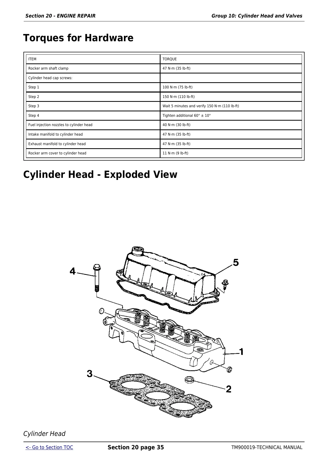
The engine material goes well beyond a basic maintenance overview. It includes engine removal and installation, disassembly and reassembly sequences, cylinder head and valve work, liner and piston service, connecting rods, crankshaft and main bearings, timing gear train, lubrication system and cooling system work. Procedures are supported by exploded views, tool references, torque values, clearances, wear limits and measurement methods. Examples include valve clearance procedures, cylinder head tightening sequence, liner protrusion measurement, piston and connecting rod installation, crankshaft journal checks, bearing clearance checks and cooling-system component repair.
General specifications provide model-specific engine, electrical, PTO and hydraulic data. The manual records 3-cylinder engine specifications, bore, stroke, displacement, compression ratio, valve clearances, idle and operating-speed information, injection pump timing, PTO data, electrical-system values, hydraulic pump displacement, flow and maximum implement pressure. It also includes repair specifications for clutch, transmissions, differential, final drives, MFWD, steering, brakes, hydraulic components, 2WD axle, three-point hitch and operator-station hardware.
Diagnostics, Checkout and System Testing
A major part of the John Deere 5103, 5203, 5204, 5303, 5403, 5045D, 5045E, 5055D, 5055E, 5065E, 5075E Tractor Technical Manual TM900019 is devoted to finding faults instead of only showing how parts come apart. The operational checkout section provides quick checks for the principal tractor systems and describes the setup condition, procedure, normal result and direction to follow when the result is not normal. That gives a practical route into deeper diagnosis after storage, during service evaluation or after repairs.
Engine diagnosis includes symptom-based checks such as rough running and low power, with references to fuel delivery, valve clearance, compression, injection timing, temperature and related systems. Power-train diagnosis addresses clutch and transmission behavior, including slippage, dragging, noise and operating checks. Steering and brake sections use normal-versus-not-normal test sequences and include pressure, flow and leakage checks. Hydraulic diagnosis covers pump and filter condition, rockshaft and selective control valve operation, flow and pressure testing, linkage adjustments and schematic-based system tracing.
Electrical and Hydraulic Reference
The electrical coverage combines component service with system theory and schematic information. It includes battery, starter and alternator work; sensors and switches; instrument panel and PTO-related components; wiring harness service; starting, charging and lighting system operation; diagnostic procedures; market-specific wiring schematics; and connector information. The manual separates certain USA, Australia, Latin America and Mexico configurations, including dedicated Mexico 5204 diagnosis and wiring material.
Hydraulic information likewise spans both repair and testing. The hydraulic pump and filter, MITA and JD rockshafts, multiple selective control valve arrangements and mid mount valve are covered in repair sections, while Section 270 adds diagnosis, hydraulic tests, adjustments and schematics. This combination helps with jobs that require both mechanical repair and verification of hydraulic pressure, flow, leakage or control response.
Component Technical Manual References
TM900019 is the machine technical manual, and it explicitly directs the technician to separate component technical manuals for some complete component-level work. The engine section states that CTM8 is also required for complete engine repair information, and the electrical section directs starter repair to CTM77. General repair specifications also reference CTM125 for engine repair specifications. These references are important when a job extends beyond the machine-level procedures and tests contained in TM900019.
Use This Manual for Repair and Diagnosis
For owners, workshops and technicians working on the covered tractors, this manual supports jobs ranging from system checkout and fault isolation to major mechanical repair. Use it to follow removal and installation procedures, inspect and measure components, compare service limits, apply listed torque values, trace electrical circuits, test hydraulic and steering performance, adjust linkages and controls, and verify repairs against the specified operating result. Having the correct procedure and specification beside the machine reduces guesswork and helps keep repairs consistent with the information given for the applicable model and configuration.
Purchase the John Deere 5103, 5203, 5204, 5303, 5403, 5045D, 5045E, 5055D, 5055E, 5065E, 5075E Tractor Technical Manual TM900019 for instant PDF access after payment. There is no physical shipping delay: the manual can be opened on a compatible phone, tablet or computer and pages can be printed when a paper reference is useful at the tractor or workbench.

Reviews
There are no reviews yet.