
John Deere 5415 5615 5715 Tractor Diagnostic Technical Manual TM606819 PDF Download
Original price was: $51.95.$34.95Current price is: $34.95.
318-page John Deere 5415, 5615 and 5715 Tractor Diagnostic Technical Manual TM606819 in PDF. System-by-system diagnosis, electrical schematics, hydraulic tests and service tool references for the 5015 Series tractors.
Description
The John Deere 5415, 5615 and 5715 Tractor Diagnostic Technical Manual TM606819 is the diagnostic and troubleshooting reference for the 5015 Series tractors, published 16APR12 (April 2012). This 318-page PDF moves system by system through the 4.5 L POWERTECH engines, fuel and air circuits, electrical wiring, CollarShift and SyncShuttle transmissions, drive systems, steering, brakes and hydraulics, pairing observable symptoms and fault paths with the test procedures, schematics and service-tool references a working technician needs to track a problem to its source. It is a diagnostic technical manual rather than a general operator’s guide, so the emphasis throughout is on how to identify, isolate and confirm a fault before repair.
File Details
- Manual type: Diagnostic Technical Manual
- Brand: John Deere
- Models: 5415, 5615, 5715 (5015 Series Tractors)
- Language: English
- Page count: 318
- File format: PDF
- Document number: TM606819
- Edition / date: 16APR12 (April 2012)
Chapters Covered
- Section 210—General
- Section 212—Observable Symptoms
- Section 213—System Diagnosis
- Section 220—Engines
- Section 230—Fuel and Air
- Section 240—Electrical
- Section 251—CollarShift and SyncShuttle Transmissions
- Section 256—Drive Systems
- Section 260—Steering and Brakes
- Section 270—Hydraulics
- Section 299—Service Tools
Sections 210, 212, 213 — General, Observable Symptoms and System Diagnosis
This opening block sets up the diagnostic method used through the rest of the book. Section 210 carries the safety messages, general specifications and references, including metric and unified-inch bolt and screw torque tables, a glossary, JIC hydraulic symbols, electrical schematic symbols and the seven-step electrical procedure, along with probe-light, circuit-type, relay-circuit and digital-multimeter guidance. Section 212 lists observable symptoms grouped by system (engine, fuel and air, electrical, transmission, drive, steering and brakes, hydraulics) and points to the matching diagnosis path. Section 213 is the working diagnosis section, with step-by-step sequences for starting, charging and start aid; CollarShift and SyncShuttle transmissions; differential lock; MFWD; rear PTO; steering; rear brakes; rear SCV; and the rear mechanical hitch.
Sections 220 and 230 — Engines, Fuel and Air
The engine chapters cover the 4.5 L John Deere POWERTECH family fitted to the 5015 Series: the PE4045DP057a in the 5415, the PE4045DP058a in the 5615, and the PE4045TP066a turbocharged engine in the 5715. Specifications, the throttle-lever adjustment and a theory-of-operation overview are provided, with full engine repair handed off to CTM104 and the mechanical fuel system to CTM207. Section 230 adds the fuel-supply route from tank through strainer, filter and injection pump to the nozzles, plus air-intake diagrams for both naturally aspirated and turbocharged configurations.
Section 240 — Electrical
This is the electrical test bench. Every procedure needed to chase a starting, charging or accessory fault is laid out component by component: battery voltage and specific-gravity checks, charge and load tests, starter amp-draw/RPM and no-load tests, alternator/regulator output, solenoid and relay checks, key switch, plug-in relay, diode pack, fuse, neutral start, PTO and PTO seat switches, light switch, flasher module, turn signal switch, fuel shut-off solenoid, blower switch and start resistor. A full set of 5015 Series wiring schematics closes the section so a fault can be traced from battery positive through the harness to ground.
Section 251 — CollarShift and SyncShuttle Transmissions
The transmission section covers clutch pedal free play adjustment and the operation of the traction and PTO clutch assemblies, with illustrations of the engaged and disengaged states. Component locations for the power train and clutch pack are included, and diagnosis is routed through the transmission CTM where full repair is needed.
Section 256 — Drive Systems
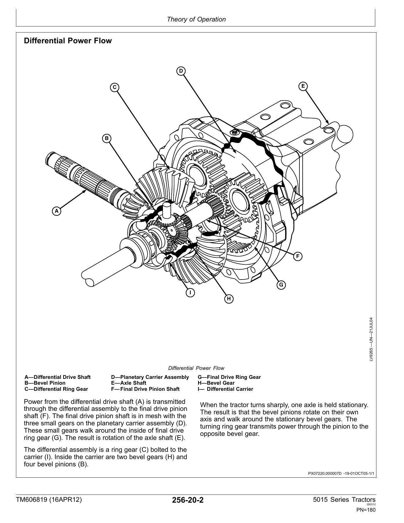
Drive-system checks cover preliminary and operational tests for the rear differential lock, PTO and MFWD, plus the PTO clutch lever linkage adjustment and park brake band and linkage adjustments. Theory sections then walk through differential power flow, differential lock engagement, final drive operation, the MFWD drop gearbox, the single-speed mechanical PTO and the park brake, each with labeled cutaway or exploded illustrations.
Section 260 — Steering and Brakes
Steering and brake work begins with preliminary and operational checks, then moves into the quantitative tests: steering pump flow, steering valve relief, steering leak-down, toe-in on both adjustable front axle and MFWD, steering stops, rear brake bleed, brake valve leak-down, brake pedal adjustment and brake retractor adjustment. Theory sections explain the steering valve in neutral/manual and power-turning modes, the brake system circuit, and brake valve operation on application and release.
Section 270 — Hydraulics
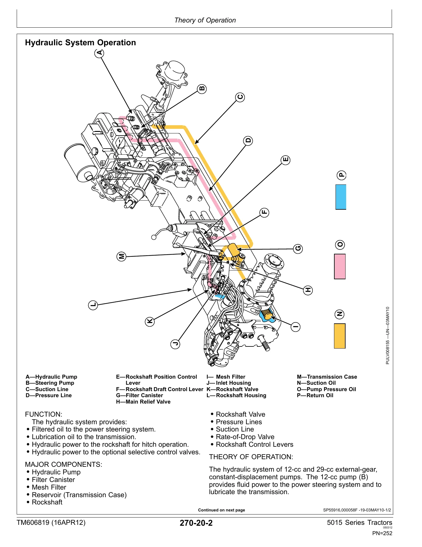
The hydraulic section is the largest single block. It covers preliminary checks, pump flow tests with and without SCV, main relief valve tests, rockshaft load-sense relief, SCV leakage, rockshaft leakage and lift-cycle tests, draft-sensing and position-control cable adjustment, rockshaft lever friction, position-sensing feedback and draft-sensing feedback. Operation is then explained through the hydraulic system, filter, pump, the two flow-regulator valves, neutral/raise/lower rockshaft valve positions, the surge relief valve, the rate-of-drop valve, rockshaft draft sensing, SCV neutral/extend-retract/float/regenerative positions and the double-acting sleeve coupler. Schematic legends for systems with and without SCV close the section.
Section 299 — Service Tools
Service tooling is documented in two groups: dealer-fabricated tools with build instructions (DFRW26, DFRW51, DFRW83, DFRW126, DFRW133) and the John Deere special service tools and kits referenced throughout the tests, including flowmeters, gauges, adapters, the current clamp probe, the digital multimeter and the battery load tester.
What This Manual Lets You Do
With the John Deere 5415 5615 5715 diagnostic manual open on the bench, a technician can move from symptom to tested conclusion instead of guessing. The observable-symptoms index and the system-diagnosis sequences together point to the right test, and the electrical, hydraulic and driveline schematics show exactly where to put a probe or gauge. The torque tables and the published pressure, flow and time specifications give a pass/fail line for each check, so adjustments and repairs are made to the manufacturer’s numbers rather than to feel. From a no-crank electrical fault to a rear SCV that only flows in one direction, the path is mapped out in the same order a shop would work it. For a mixed fleet, the single-volume coverage matters: the 5415, 5615 and 5715 share the same diagnostic framework, so a procedure learned on one model carries directly to the next. Terminal numbers, circuit numbers, wire colours and pressure test points are the ones actually on these tractors, not generic ones borrowed from another manual. Because the manual pairs each test sequence with theory, it also builds understanding: a technician can read why the rockshaft flow-regulator valves meter in two stages, why the brake valve equalizing valves exist, or how the steering valve stays in a closed loop if pressure drops, context that reduces repeat comebacks.
IMAGES PREVIEW
Instant PDF Delivery
The complete TM606819 diagnostic technical manual is delivered as a PDF the moment payment clears, with no shipping, no waiting on a disc and no regional restriction. Open it on a laptop or tablet in the shop, print the section you need for the bench, and keep the full manual handy on any device. The 318-page file covers all three 5015 Series tractors in one document, so it stays useful across the whole fleet.
Reviews
There are no reviews yet.