
John Deere 6010 6110 6210 6310 6410 6510 6610 6810 6910 6910S & SE Diagnosis and Tests Service Manual TM4552 – 2003 PDF
Original price was: $74.95.$49.95Current price is: $49.95.
Comprehensive John Deere TM4552 Diagnosis and Tests Service Manual for 6010, 6110, 6210, 6310, 6410, 6510, 6610, 6810, 6910, 6910S and applicable SE tractors. Covers service-code diagnostics, observable symptoms, engine testing, fuel and cooling systems, electrical schematics, electronic controls, transmission diagnostics, drive systems, steering, brakes, hydraulics, TLS front axle, operator cab systems and dealer-fabricated special tools.
Description
John Deere 6010–6910S and SE Diagnosis & Tests Service Manual TM4552
This John Deere TM4552 Diagnosis and Tests Service Manual is the detailed troubleshooting and testing reference for 6010, 6110, 6210, 6310, 6410, 6510, 6610, 6810, 6910 and 6910S tractors, together with the applicable SE versions identified in the manual. Dated March 2003, it is written for experienced technicians and concentrates on the information needed to diagnose faults, analyse system operation, perform tests and adjustments, interpret service codes and verify repairs.
At more than five thousand pages, this is an exceptionally deep diagnostic reference rather than a basic owner’s handbook. It works through the tractor as a collection of interacting electrical, electronic, transmission, hydraulic, steering, braking, engine-support and cab systems. The manual repeatedly ties symptoms and service codes to specific checks, diagnostic addresses, circuit tests, pressure measurements, component tests, calibration routines, functional schematics and system operating descriptions.
Important: TM4552 is a Diagnosis and Tests / Operation and Test manual. Certain procedures refer the technician to corresponding repair or engine technical manuals for component disassembly or internal engine repair. Its strength is fault isolation, testing, adjustment, system theory and diagnostic decision-making.
File Details
- Manual type: Diagnosis and Tests Service Manual
- Brand: John Deere Agriculture
- Models: 6010, 6110, 6210, 6310, 6410, 6510, 6610, 6810, 6910, 6910S; SE 6010, 6110, 6210, 6310, 6410, 6510 and 6610
- Document number: TM4552
- Date: March 2003
- Language: English
- Pages: 5428
- Format: PDF
Built Around Real Diagnostic Work
The John Deere 6010 6110 6210 6310 6410 6510 6610 6810 6910 6910S diagnosis manual is structured around the jobs a technician actually performs when a tractor arrives with a warning, stored service code, abnormal system behaviour or a complaint that cannot be solved by inspection alone. Diagnostic sequences commonly begin with preliminary checks, continue through controller addresses or measured values, and then direct the technician to circuit, pressure, sensor, solenoid, harness or mechanical checks according to the result.
The service-code material is particularly extensive. Separate diagnostic groups are provided for controllers including BCU, BIF, ECU, HCU, PCU, PEC, PLC, RCU, SFA, TCU and UIC. Procedures include code interpretation, controller input and output checks, voltage and resistance measurements, harness and connector inspection, calibration checks and cross-references to the relevant functional system.
The manual also handles faults that do not present as a stored electronic code. Its observable-symptom section covers electrical problems, PowrQuad/PowrQuad Plus/AutoQuad transmission symptoms, drive-system faults, steering and brake symptoms and hydraulic complaints. This makes TM4552 useful both for electronic troubleshooting and for faults that have to be isolated from machine behaviour.
Chapters Covered
- Section 210 – SAFETY
- Section 211 – SERVICE CODE DIAGNOSTICS
- Section 212 – OBSERVABLE SYMPTOMS
- Section 220 – ENGINE
- Section 230 – FUEL, AIR INTAKE AND COOLING SYSTEMS
- Section 240 – ELECTRICAL SYSTEM
- Section 245 – ELECTRONIC CONTROL UNITS
- Section 250 – SYNCROPLUS TRANSMISSION
- Section 251 – POWER REVERSER TRANSMISSION
- Section 252 – POWER SHIFT TRANSMISSION
- Section 253 – AUTOPOWR TRANSMISSION
- Section 255 – POWRQUAD, POWRQUAD PLUS AND AUTOQUAD II TRANSMISSIONS
- Section 256 – DRIVE SYSTEMS
- Section 260 – STEERING AND BRAKES
- Section 270 – HYDRAULIC SYSTEM
- Section 280 – MISCELLANEOUS
- Section 290 – OPERATORS CAB
- Section 299 – SPECIAL TOOLS (DEALER-FABRICATED)
Service Code Diagnostics and Observable Symptoms
The diagnostic sections provide dedicated service-code procedures for the tractor’s major electronic controllers. Fault isolation is supported by controller addresses, signal states, voltage ranges, resistance checks, wiring references, calibration information and step-by-step result paths. The observable-symptom material adds troubleshooting for electrical functions, transmission behaviour, drive-system issues, steering and brakes, and hydraulics when no single controller code provides the complete answer.
Engine, Fuel, Air Intake and Cooling Systems
Engine-related material includes tests as well as system diagnosis for fuel delivery, air intake, cooling and cold-weather starting aids. The manual includes checks and adjustments for items such as fuel supply, air restriction, cooling-system leakage, sensors and associated electronic controls. Diagnostic information is tied to measured specifications rather than relying only on symptom descriptions.
Electrical System and Wiring Diagnosis
Section 240 is one of the largest parts of TM4552. It includes general electrical diagnosis, functional schematics and wiring diagrams for 6010-6910S tractors, SE tractors, 2-Post ROPS configurations and AutoPowr-equipped machines. Separate circuit-testing and sub-system diagnostic groups support these configurations. Data BUS coverage includes both system information and diagnosis, while adjustment and component-testing groups provide the checks needed to verify switches, sensors, relays, solenoids and related circuits.
Electronic Control Units
The electronic-control section explains diagnostic procedures and provides reference material for BCU, BIF, ECU, HCU, PCU, PEC, PLC, RCU, SFA, TCU and UIC systems. The manual covers safe electronic testing practices, controller identification and diagnostic-address use, along with the supporting tests needed when a controller reports an input, output, calibration or communication fault.
SyncroPlus, Power Reverser and PowerShift Transmissions
Dedicated sections cover operational checkout, troubleshooting, tests, adjustments and operating theory for SyncroPlus, Power Reverser and Power Shift transmissions. SyncroPlus coverage extends into Perma Clutch II, gear, creeper and range transmission operation. Power Reverser coverage includes the reverser module and gear transmission, while Power Shift material provides operational and hydraulic diagnostic information for the system.
AutoPowr, PowrQuad, PowrQuad Plus and AutoQuad II
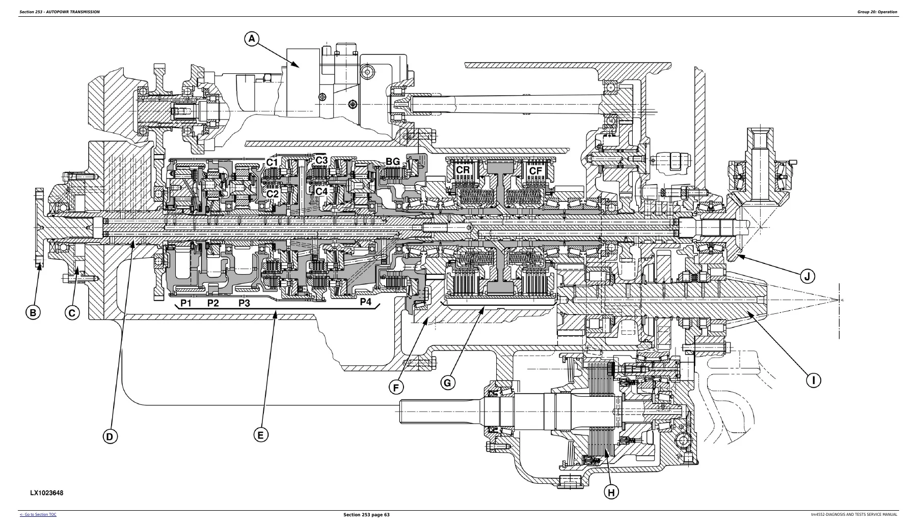
AutoPowr diagnosis is divided among UIC, TCU and PLC functions, followed by tests, adjustments and transmission operation. PowrQuad, PowrQuad Plus and AutoQuad II coverage includes operational checkout, troubleshooting, pressure and adjustment work, transmission operation, creeper and range systems, hydraulic schematics and transmission-control information. The manual’s illustrations include detailed sectional and hydraulic views that help connect diagnostic readings with the components and flow paths inside the transmission.
Drive Systems, PTO and Final Drives
The drive-system section covers operational checkout, troubleshooting and tests for the front-wheel-drive clutch, differential, final drives, rear PTO options and front PTO. Diagnostic procedures can lead from electrical checks into hydraulic pressure tests or mechanical fault isolation, helping distinguish a switch or solenoid problem from a pressure, clutch or driveline fault.
Steering and Brakes
Steering and brake diagnosis includes operational checkout, troubleshooting, tests and adjustments. System coverage includes hydrostatic steering, hydraulic brakes, handbrake, hydraulic trailer brake and air brake systems. The manual supplies operating information alongside diagnostic checks so pressure or functional results can be interpreted in the context of how each system is intended to work.
Hydraulic System
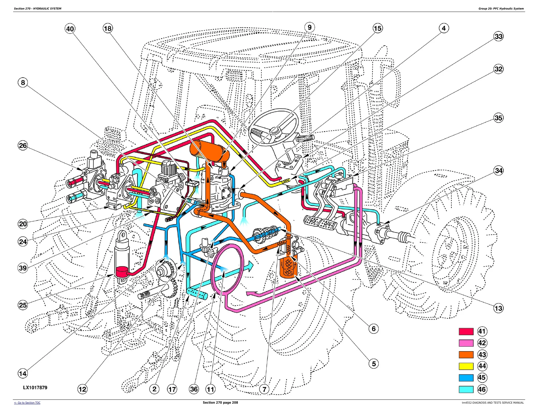
The hydraulic chapter provides substantial coverage of both PFC and PC hydraulic systems. It includes operational checks, troubleshooting, tests, adjustments and system theory, followed by detailed treatment of the charge oil pump, hydraulic pumps, valves, oil cooler, filter, rockshaft, selective control valves, couplers and independent control valve. Symbolic, schematic and three-dimensional hydraulic views show the relationships between pumps, valves, steering, brakes, rockshaft, PTO lubrication and external hydraulic consumers. The testing material includes pressure and flow diagnosis, control calibration and checks for hydraulic components and circuits.
TLS Front Axle and Operator Cab
Section 280 concentrates on the TLS front axle with operational checkout, troubleshooting, tests, adjustments and operating theory. The operator-cab section then covers cab-system checkout and troubleshooting for air conditioning, ventilation, heating and the operator’s seat, together with operating descriptions for the climate-control systems.
Dealer-Fabricated Special Tools
The final section identifies special tools intended to support diagnostic and service procedures described throughout the manual. Tool references also appear within individual tests where a particular adapter, gauge, harness or fabricated service tool is required to obtain the specified measurement safely and correctly.
A Serious Diagnostic Reference for 6010-Series Tractors
If you are tracing an intermittent electrical fault, interpreting a controller service code, checking a transmission-pressure problem, verifying PTO operation, diagnosing steering or brake performance, testing rockshaft and SCV hydraulics, following a CAN/CCD communication problem or working through an AutoPowr, PowrQuad or SyncroPlus complaint, the John Deere TM4552 Diagnosis and Tests Service Manual gives you the procedures, diagrams, test points and specifications needed to work methodically instead of replacing parts by guesswork.
Correct diagnostic sequences matter on machines with interconnected controllers, hydraulic systems and transmission electronics. Having the proper test values and system diagrams at hand helps separate electrical, hydraulic and mechanical causes and provides a repeatable way to confirm the fault before repair and verify operation afterwards.
IMAGES PREVIEW
Your manual is supplied as an instant PDF download after purchase. There is no shipping delay and no physical book to wait for. Open it on a computer, tablet or phone and print the pages you need for workshop use.
Reviews
There are no reviews yet.