
John Deere 6100D 6110D 6115D 6125D 6130D Tractor Diagnostic Technical Manual TM608719 – PDF Download
Original price was: $74.95.$49.95Current price is: $49.95.
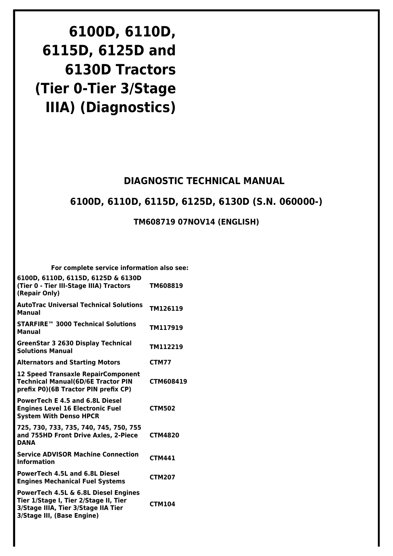
Complete John Deere Diagnostic Technical Manual TM608719 for 6100D, 6110D, 6115D, 6125D and 6130D Tractors (S.N. 060000-). Full DTC diagnostics, electrical schematics, hydraulic test procedures, engine and transmission system troubleshooting. Instant PDF download.
Description
John Deere 6100D, 6110D, 6115D, 6125D and 6130D Tractors — Diagnostic Technical Manual TM608719
This is the complete Diagnostic Technical Manual for John Deere 6100D, 6110D, 6115D, 6125D and 6130D Tractors (Tier 0 – Tier 3/Stage IIIA) covering serial number 060000 and up. Published under document number TM608719 with a 07NOV14 edition date, this manual delivers the full diagnostic, testing and troubleshooting content required to isolate faults and service these tractors correctly. Every section is written for the experienced technician — diagnostic trouble code charts, observable symptom paths, system theory of operation, electrical schematics, component and connector pinouts, and step-by-step test procedures are all included in one PDF.
File Details
- Manual Type: Diagnostic Technical Manual
- Brand: John Deere
- Models Covered: 6100D, 6110D, 6115D, 6125D, 6130D Tractors
- Serial Number: 060000-
- Document Number: TM608719
- Edition / Date: 07NOV14 (English)
- Language: English
- Page Count: 1345
- File Format: PDF
Chapters Covered
- Section 210 – General Information
- Section 211 – Diagnostic Trouble Codes
- Section 212 – Observable Symptoms and System Diagnostics
- Section 220 – Engine
- Section 230 – Fuel, Air Intake, Exhaust and Cooling
- Section 240A – Electrical General and Theory of Operation
- Section 240B – Electrical Schematics
- Section 240C – Electrical Components and Connectors
- Section 240D – Electrical Tests and Adjustments
- Section 245 – Electronic Control Units
- Section 250 – Drive Systems and Transmissions
- Section 260 – Steering and Brakes
- Section 270 – Hydraulics
- Section 290 – Cab/Open Operator’s Station
- Section 299 – Special Tools
Section 210 – General Information
Covers safety procedures for working on these tractors, general references, technical specific references, metric and unified inch bolt torque value tables, a detailed glossary of abbreviations and terms, and feature/accessory availability tables across all five models. Includes the essential preliminary checks and how-to-use guidance for the rest of the manual.
Section 211 – Diagnostic Trouble Codes
The core of the diagnostic workflow. Organised by control unit — CCU, ECU, ICC and PTR code diagnostics — this section lists every diagnostic trouble code with its SPN/FMI designation, a description of what triggers it, control unit response, and a structured diagnostic path with operational checks and code verification steps. Examples include CCU 000096.03/04 fuel level sensor circuit, CCU 000110.00/03/04/16 engine coolant temperature sensor, CCU 001638.00/03/04/16 hydraulic oil temperature, CCU 523907.02 PTO remote enable switch conflict, CCU 524252.05 rear PTO solenoid circuit fault, PTR 000070.14 park brake engaged during movement, PTR 000598.02/04 clutch switch faults, plus non-tractor ECU codes for the engine control unit.
Section 212 – Observable Symptoms and System Diagnostics
When codes don’t tell the full story, this section provides system-level diagnostic paths organised by observable symptom. Covers engine diagnostics, fuel/air intake/exhaust and cooling, electrical system diagnostics (starting, charging, lighting, connectors, horns, power outlets), electronic control unit diagnostics (CAN system, CCU, ECU, ICC, PTR), drive systems and transmission diagnostics, steering and brake diagnostics, hydraulic diagnostics (mid-mount SCV, rear SCV, mechanical hitch, hydraulic trailer brake), and cab/open operator station diagnostics (HVAC, radio, seat, wiper). Each diagnostic path guides you through preliminary checks, operational checks, pressure tests, flow tests, and component isolation with go/no-go results.
Section 220 – Engine
Vehicle-specific engine diagnostic information for the 4045 PowerTech engine, including engine calibrations, preliminary checks, operational checks, theory of operation, schematics, component and connector information, and test procedures. Engine performance variables such as fuel temperature effects on horsepower, air temperature effects, fuel specific gravity, ballasting, elevation, filter condition, cooling fan load, alternator load, air conditioning compressor load, hydraulic demand, fuel supply pressure and worn injector diagnosis are all covered in detail.
Section 230 – Fuel, Air Intake, Exhaust and Cooling
Diagnostic content covering the air intake system (air cleaner housing, primary and secondary elements, turbocharger, charge air cooler), cooling system theory of operation including coolant flow through oil cooler plates, main coolant gallery, coolant jacket, block deck passages, cylinder head, thermostat operation (including EGR cooler thermostat on Tier 3/Stage IIIA engines), exhaust system, and fuel system diagnostics.
Sections 240A/B/C/D – Electrical System
The complete electrical diagnostic suite. 240A covers circuit malfunction types (high resistance, open, grounded, shorted), circuit types (electrical vs electronic), electrical designators, schematic symbols, relay circuit types, using a digital multimeter, using a probe light, visual inspection, CAN communication system theory, and control unit theory of operation. 240B contains the full electrical schematics for every subsystem: key switch/starter/alternator, neutral start, accessory power, horn, light switch and headlights, cab and OOS work lighting, turn signal and hazard warning lights, trailer connector, back-up alarm, beacon light, mid-mount SCV, power outlets, heater, air conditioning, front/rear windshield wipers, dome light/door switch/radio, air seat, instrument cluster control, seat switch and rear PTO switch, ELX relay and fuses, MFWD, brake switch, EHC, engine control unit and Controller Area Network. 240C provides component and connector information with pinouts, wire colors, circuit functions and location views for every electrical component. 240D contains the electrical test and adjustment procedures: connector test, diode test, fuse test, light test, motor test, pump test, relay test, resistor test, sensor test, solenoid test, switch test, A/C compressor circuit test, alternator circuit test, battery inspection test, CAN network voltage checks, ECU/EHC/ICC control unit tests, and sensor power and ground tests.
Section 245 – Electronic Control Units
Diagnostic addresses and configuration data for the Chassis Control Unit (CCU), Engine Control Unit (ECU), Instrument Cluster Control Unit (ICC) and Power Train Reverser (PTR). Includes control unit address access methods (Service ADVISOR, on-board diagnostics via ICC, performance monitor), recall/record/clear codes procedures, programming control units, control unit locations and identification, VIN security fault diagnosis, servicing electronic control units, welding precautions, and connector cleanliness. CCU addresses cover MFWD configuration, rear PTO configuration, tire rolling circumference, secondary handbrake configuration, engine hours, and engine function configuration. ICC addresses cover units selection, auto clear DTC hours, backlight dimming, air filter configuration, battery charge configuration, PTO speed display, hi/lo transmission gear display, fuel gauge configuration, and warning/stop levels. PTR addresses cover transmission type, clutch pedal potentiometer voltages, forward/reverse clutch pressures, solenoid currents, PowerShuttle setup, high speed shuttle shift limit, and seat switch polarity.
Section 250 – Drive Systems and Transmissions
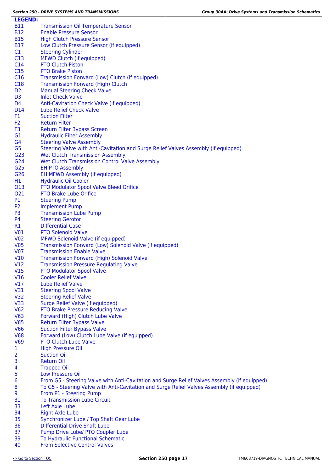
Complete transmission diagnostics including preliminary checks, operational checks, theory of operation, hydraulic schematics for 12-speed wet clutch and 12-speed PR drivetrains, component information with manifold exploded views, and test procedures. Tests include transmission pump pressure test, transmission clutch engagement pressure test, transmission pump flow test, lube pressure test, and PTO clutch leak test. Each test gives equipment installation steps, test procedures, specifications with both cold (38°C/100°F) and hot (65°C/150°F) oil temperature values, and result interpretation.
Section 260 – Steering and Brakes
Brake system preliminary checks, operational checks, theory of operation (including engagement ball, actuator plates, friction discs, separator plates, park brake and secondary hand brake), hydraulic trailer brake operation. Steering system preliminary checks, operational checks, steering valve theory of operation (neutral, turn engine on, turn engine off), steering valve with anti-cavitation and surge relief valves theory. Steering tests include cooler flow test, steering relief valve test, steering valve leak test, steering pump pressure test and steering pump flow test. Brake adjustment procedures include brake pedal linkage and pedal travel adjustment.
Section 270 – Hydraulics
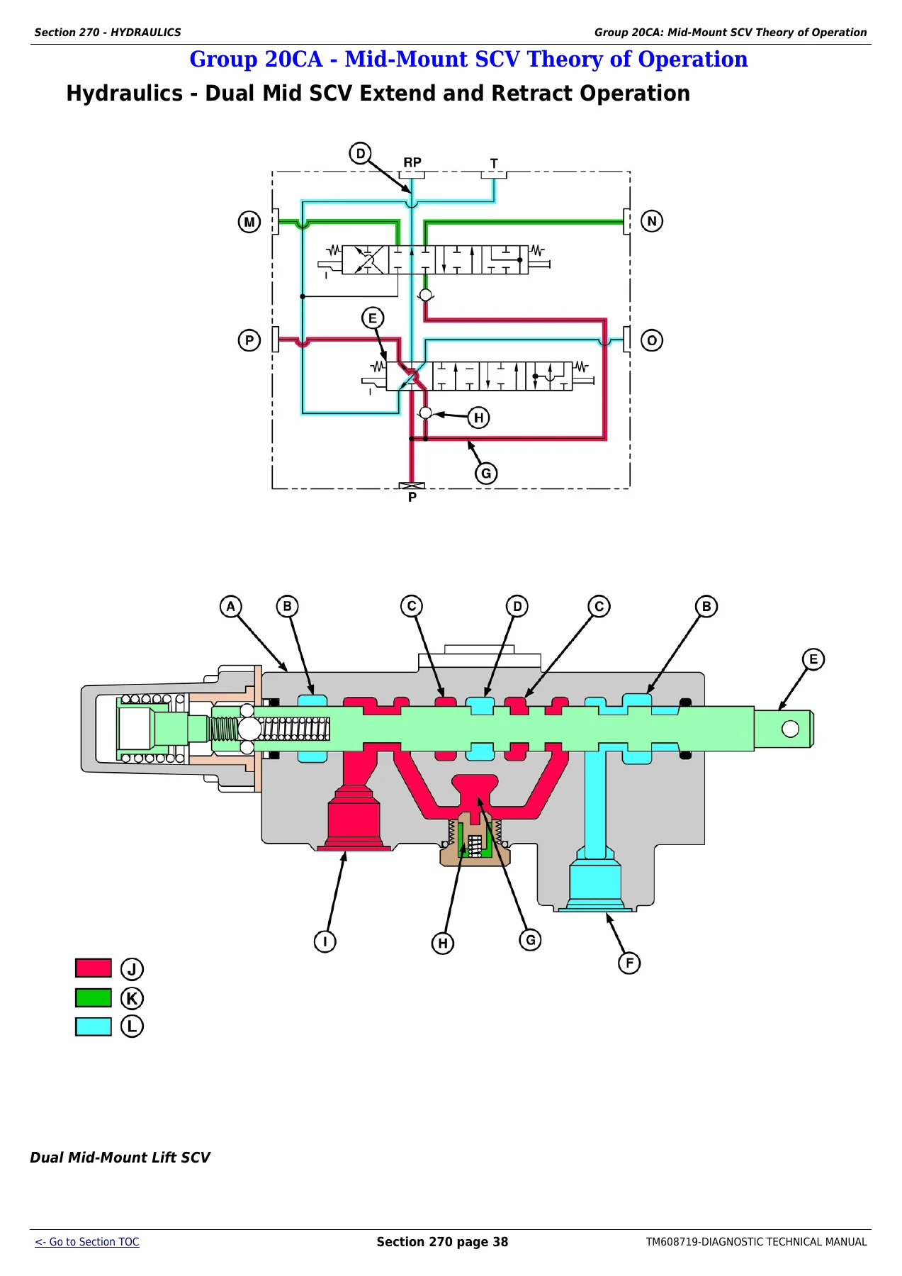
Full hydraulic system diagnostics covering preliminary checks, operational checks (hitch, rear SCV, mid-stack SCV, hydraulic trailer brake), system theory of operation, quick disconnect coupler operation, mechanical hitch theory (neutral, raise, lower, main relief valve, rate-of-drop valve, surge relief valve), mid-mount SCV theory (dual and triple, extend/retract, float, neutral, regenerative, flow control), rear SCV theory (single, dual and triple, extend/retract, float, neutral, continuous detent, kick-out detent, no detent, priority flow control), and hydraulic trailer brake theory of operation. Hydraulic tests include heating hydraulic oil, hitch cylinder supply pressure test, hitch load-sense relief valve adjustment, hitch surge relief valve test, hydraulic trailer brake valve test, implement pump flow test, implement relief valve adjustment, kick-out detent pressure test, main relief valve test and SCV leak down test.
Section 290 – Cab/Open Operator’s Station
HVAC diagnostics including preliminary checks (evaporator core, recirculation air filter, fresh air filter, grille screens, cooler elements, radiator, condenser, compressor wiring, fuses F23 and F25, A/C lines), operational checks (blower function, compressor clutch engagement, air duct distribution, system cooling, temperature drop, engine temperature, heater valve operation), theory of operation for the complete A/C cycle, compressor, condenser, dual pressure switch, evaporator, expansion valve, receiver/dryer, temperature control switch, ON/OFF switch, heater temperature control knob, heating and ventilation, air seat operation and mechanical seat operation. Tests include A/C system pressure test, A/C system static pressure test, temperature drop test, heater temperature control cable adjustment and A/C temperature control switch adjustment.
Section 299 – Special Tools
Complete list of SERVICEGARD tools required for the diagnostic procedures in this manual, including part numbers, descriptions and usage instructions. Also includes dealer-fabricated tool assembly drawings and specifications. Tools covered include pressure gauges, hydraulic testers, diagnostic receptacles, couplers, fittings, hoses, adapters and complete test kits.
What This John Deere Diagnostic Manual Enables You to Do
The TM608719 Diagnostic Technical Manual is the essential reference for any technician or owner working on John Deere 6100D, 6110D, 6115D, 6125D or 6130D tractors. With full diagnostic trouble code coverage across all control units — CCU, ECU, ICC and PTR — you can read, interpret and clear fault codes with confidence. The manual goes far beyond simple code reading: it provides the complete diagnostic path for each code, including operational checks, verification steps, and component-level tests that lead directly to the failed part.
For electrical problems, the full set of schematics (SE1 through SE32) and the component/connector database give you pinouts, wire colors, circuit functions, and component locations for every electrical component on the machine. The electrical test procedures — connector test, diode test, fuse test, relay test, sensor test, solenoid test, switch test, motor test, pump test — are written to be followed step by step, with clear pass/fail criteria.
For hydraulic and transmission problems, the manual provides pressure test and flow test procedures with exact specifications, plus complete theory of operation for the hitch, mid-mount SCV, rear SCV, hydraulic trailer brake, wet clutch transmission and PR transmission. You can diagnose low pressure, low flow, leak-down, modulation and detent problems with the same procedures the dealer uses.
For engine performance issues, the engine diagnostics section and engine performance variables chapter help you isolate fuel, air, cooling and electronic control problems. The engine power checking procedure with the power check form (2100 rpm down to 1500 rpm in 100 rpm increments) lets you document and evaluate engine output.
Why This Manual Matters
Correct diagnostic procedures save time and prevent expensive mistakes. Rather than replacing parts by guesswork, the TM608719 manual guides you through a logical sequence of checks that pinpoint the failed component. The specifications throughout the manual — pressure values, flow rates, resistance ranges, voltage ranges, torque values, adjustment limits, temperature thresholds — give you the exact numbers needed to verify repairs. For a machine as complex as the John Deere 6100D through 6130D series, with electronic engine control, electrohydraulic transmission control, CAN bus communications, and multiple control units, having the diagnostic manual is the difference between a quick fix and a long, frustrating repair.
IMAGES PREVIEW
Instant PDF Delivery
This diagnostic technical manual is delivered as an instant PDF download after payment. No shipping, no waiting for a physical book. The PDF works on any device — desktop, laptop, tablet or smartphone — and every page is printable so you can take the relevant sections to the workshop. Whether you’re diagnosing a fault code, tracing an electrical circuit, testing hydraulic pressure, or performing a transmission calibration, you’ll have the complete John Deere TM608719 diagnostic manual at your fingertips.
Reviews
There are no reviews yet.