
John Deere 6120 to 6420 and 6120L to 6520L Tractors Technical Repair Manual TM4647 – PDF Download
Original price was: $59.95.$39.95Current price is: $39.95.
John Deere Technical Repair Manual TM4647 for 6120, 6220, 6320, 6420, 6120L, 6220L, 6320L, 6420L and 6520L tractors. Engine, fuel, electrical, transmission, hydraulic, steering and cab repair procedures with specifications and diagrams.
Description
John Deere 6120 to 6420 and 6120L to 6520L Tractors — Technical Repair Manual TM4647
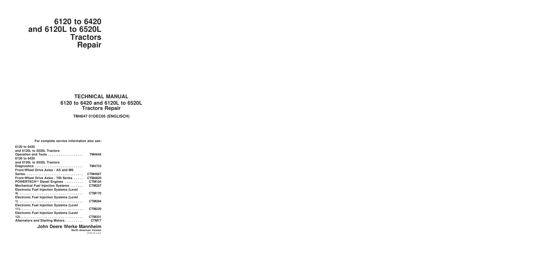
This is the John Deere Technical Repair Manual TM4647 for the 6120, 6220, 6320, 6420, 6120L, 6220L, 6320L, 6420L and 6520L tractors. Published December 2005, this PDF extract covers the major service and repair procedures for these machines, written for experienced technicians who need factory-derived specifications, removal and installation sequences, and reconditioning instructions.
This is not a general owner’s guide. It is a workshop-level repair manual containing the technical data and step-by-step procedures needed to diagnose, disassemble, repair and reassemble the tractor’s major systems. Whether you are servicing a SyncroPlus transmission, troubleshooting a Denso or Stanadyne fuel system, or pulling the engine for an overhaul, TM4647 is the reference document to have on the bench.
File Details
- Manual Type: Technical Repair Manual
- Brand: John Deere
- Models Covered: 6120, 6220, 6320, 6420, 6120L, 6220L, 6320L, 6420L, 6520L
- Document Number: TM4647
- Edition/Date: 01DEC05 (01 December 2005)
- Language: English
- Page Count: 320 pages (extract)
- Format: PDF
Chapters Covered
This extract of TM4647 is organized into the following sections:
- Section 05 — Safety
- Section 10 — General Information
- Section 20 — Engine
- Section 30 — Fuel, Air Intake, Cooling and Exhaust Systems
- Section 40 — Electrical System
- Section 50 — SyncroPlus Transmission
- Section 51 — Power Reverser Transmission
- Section 53 — AutoPowr/IVT Transmission
- Section 55 — PowrQuad, PowrQuad Plus and AutoQuad Transmissions
- Section 56 — Drive Systems
- Section 60 — Steering and Brakes
- Section 70 — Hydraulic System
- Section 80 — Miscellaneous
- Section 90 — Operator’s Cab
- Section 99 — Special Tools
Section 05 — Safety
Safety measures covering the full range of workshop hazards: high-pressure fluid injection, battery explosions, acid burns, cooling system pressure release, welding and heating precautions, ROPS installation, and safe handling of electronic control units. Essential reading before any repair work begins.
Section 10 — General Information
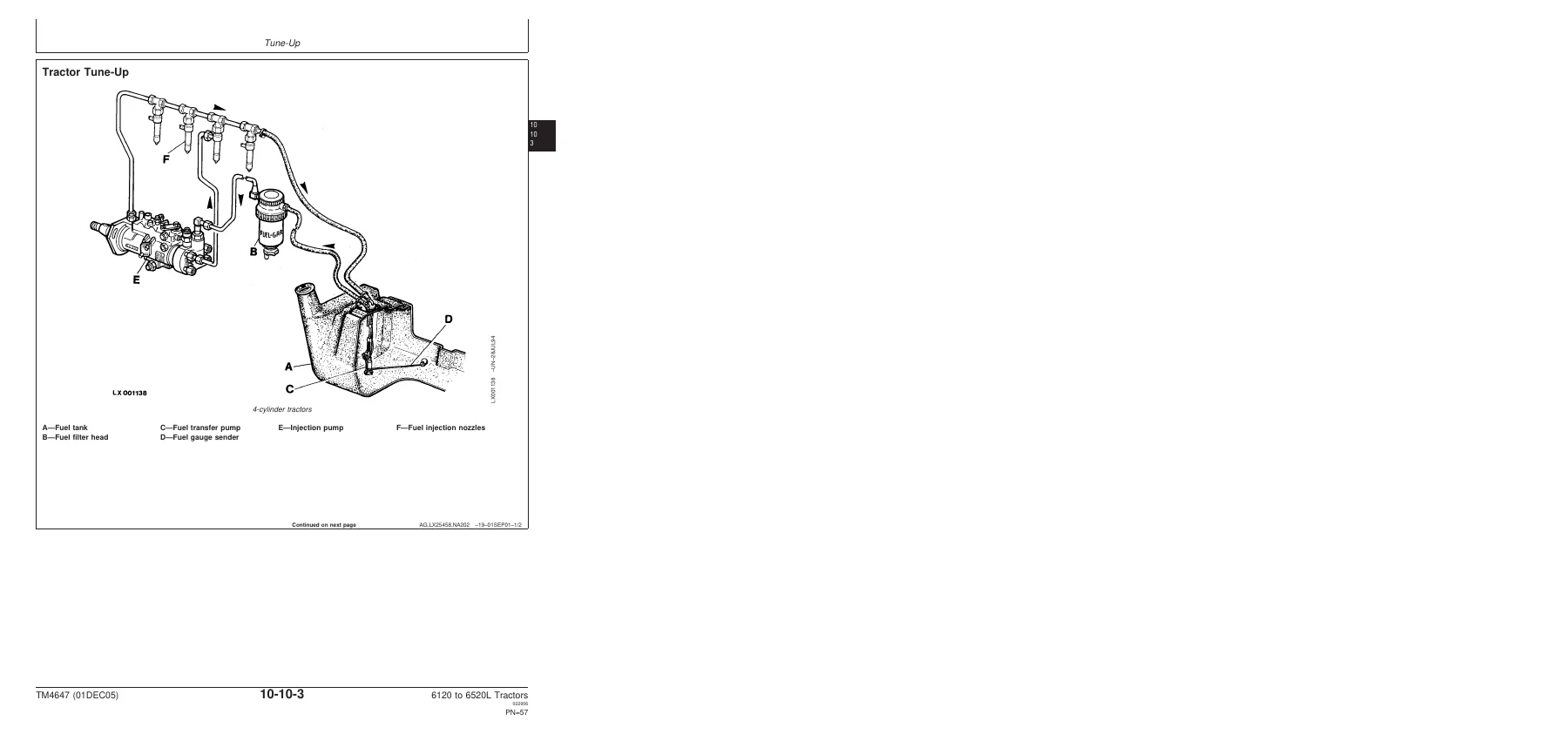
This section carries the specification backbone of the manual. Engine specifications include bore, stroke, displacement, compression ratio, valve clearances, slow and fast idle speeds, rated engine speed, and PTO power and torque figures for every model in the range. Transmission, hydraulic, electrical and cooling system specifications are laid out by model. Capacities for fuel, coolant, engine oil, transmission/hydraulic oil and front-wheel drive axles are provided. Also included are diesel fuel requirements, engine oil recommendations by engine serial number, transmission and hydraulic oil specifications, coolant requirements, grease specifications, bolt and screw torque tables (metric and inch), hydraulic fitting torques, product identification locations and sub-assembly serial number plates. The tune-up section covers preliminary engine tests, air cleaner servicing, fuel filter replacement and bleeding procedures, battery maintenance, neutral start circuit checks, and final engine and tractor operation checks.
Section 20 — Engine
Engine removal and installation procedures for 4-cylinder PowerTech engines. Includes specifications for engine mounting screws, front engine supports, U-joint shaft to input flange, and frame mountings. Step-by-step removal covers battery disconnection, hood removal, coolant draining, floor-plate removal, U-joint shaft disconnection, muffler and exhaust pipe removal, coolant hose and fuel hose disconnection, wiring harness disconnection, air cleaner removal, air-conditioning component handling, front frame suspension and removal, and engine lifting with JDG19 lifting eyes and load-positioning sling D01042AA. Installation reverses the procedure with all relevant torque values.
Section 30 — Fuel, Air Intake, Cooling and Exhaust Systems
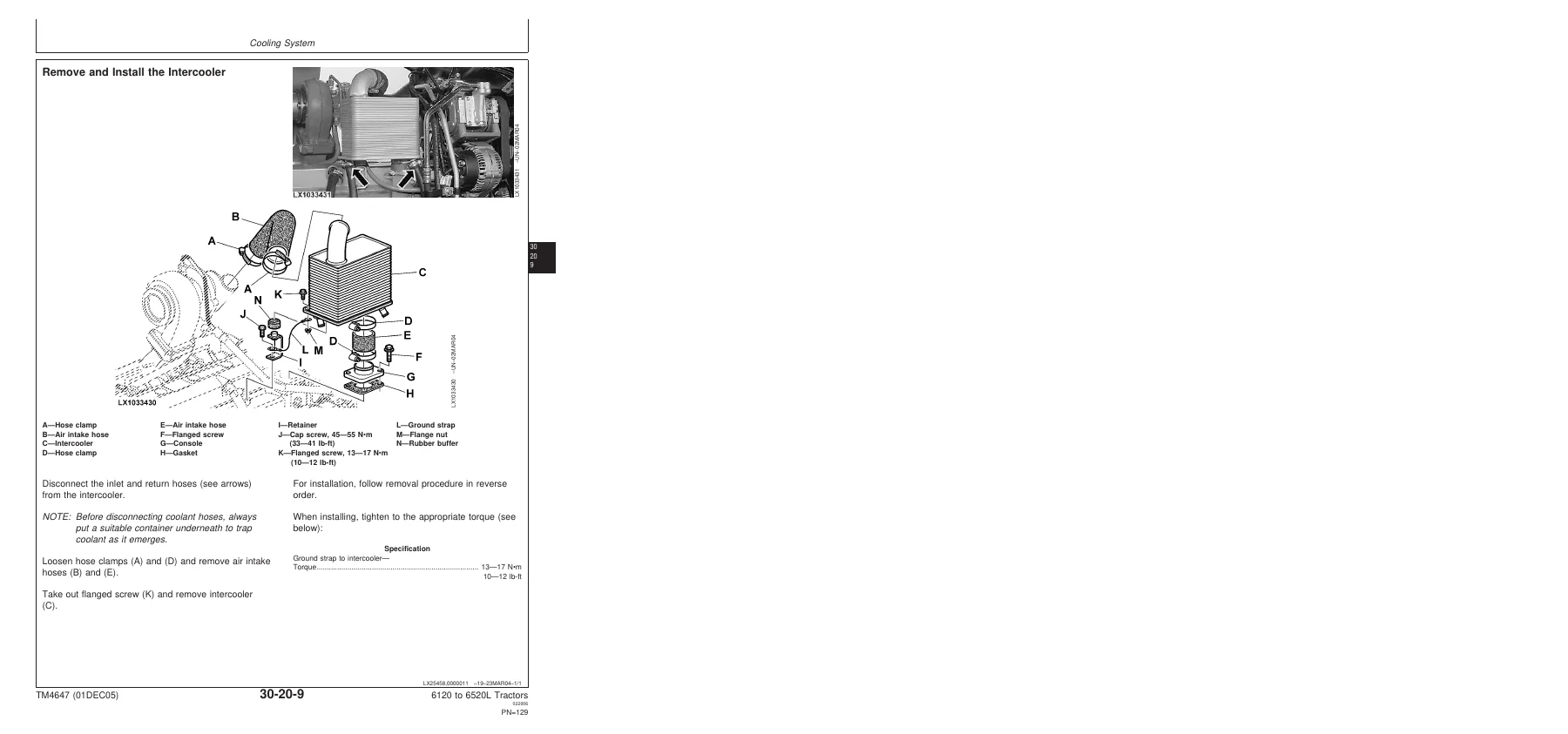
Covers speed control adjustment (hand throttle lever, accelerator pedal, speed control linkage for mechanical and electronic systems), potentiometer replacement procedures, fuel system components (fuel tank removal and installation, fuel gauge sending unit, fuel transfer pump, fuel filter, bleeding procedures for Denso and Stanadyne injection pumps), air intake system (air filter element, safety element, restriction sending unit), cooling system (radiator removal and installation, fan and viscous fan drive, intercooler, expansion tank, thermostat valve, coolant filling, drive belt tension and replacement, fan console repair), cold-weather starting aids (fuel preheater, electrical starting aid, coolant heater), and exhaust system (muffler and pipe installation for top-right and bottom-right configurations).
Section 40 — Electrical System
Connector repair procedures for WEATHER PACK, METRI PACK, CRIMP SNAP IN, KOSTAL and DEUTSCH connectors, including terminal extraction and installation, wire seal selection, and crimping tool usage. Fuse and relay box terminal extraction for cab and open operator’s station tractors. Wiring harness summaries by transmission type and engine tier (TIER I and TIER II), covering harness removal and installation for power supply, engine, starting aid, headlights, front PTO, cab, cowl, shift console, transmission shift, hand throttle, clutch sending unit, power outlet sockets, ECU, SIC control unit, multi-function unit, wiper switches, cab roof, worklights, rear window wiper, fan and air-conditioner, turn signal lights, transmission ends, stepper motors, service, rear-view mirrors, access step lighting, battery cut-off switches, GreenStar components, JDLink, back-up alarms and AutoTrac. Ground point locations for cab and open station.
Section 50 — SyncroPlus Transmission
Clutch housing removal and installation, gear transmission removal and installation, transmission shift controls (gear shift mechanism, range shift mechanism, shift unit adjustment, clutch pedal adjustment), Perma Clutch II module (clutch removal, reconditioning and installation, transmission oil pump removal, reconditioning and installation, hydraulic valves including engagement override, clutch cooling, cooling pilot, filter relief, pressure-regulating, lube relief, cooler relief and clutch pedal valves), and gear transmission reconditioning (disassembly, gear reconditioning, shift cover reconditioning, neutral start switch adjustment).
Section 51 — Power Reverser Transmission
Power reverser module removal and installation, gear transmission removal and installation, shift controls (gear shift mechanism, range shift mechanism, forward/reverse control, reverse drive lever and linkage adjustment, clutch pedal adjustment), power reverser module reconditioning (disk brake removal, reconditioning and installation, clutch and planetary carrier removal, reconditioning and installation, transmission oil pump removal, reconditioning and installation, hydraulic valves including pressure-regulating, cooling pilot, clutch cooling, engagement override, filter relief, cooler relief, lube relief, sump, accumulator piston, forward/reverse, FWD/REV cooling control, modulator, connecting and clutch pedal valves), and gear transmission reconditioning.
Section 53 — AutoPowr/IVT Transmission
AutoPowr/IVT transmission removal and installation, shift controls (speed control lever reconditioning, reverser control, clutch actuation mechanism, manual park lock release mechanism), input housing reconditioning (speed sending unit replacement, pressure sending unit replacement, thermostat valve replacement, filter by-pass valve replacement, oil filter replacement, system pressure control block removal and installation, transmission oil pump removal, reconditioning and installation, vibration damper, front plate, clutch control block removal, reconditioning and installation, housing separation and joining, BG disk brake removal and installation, shift turret removal, reconditioning and installation, hydrostatic unit removal, installation and output shaft reconditioning, shaft gap measurement, wiring harness and fitting replacement), output housing reconditioning (speed sending units, pressure sending unit, bleed valve, park lock control block and cam, pneumatic pump, vibration damper, direction turret and reverse intermediate shaft, hydrostatic unit drive shaft, through-drive shaft, drive gear and idler gear), and differential drive shaft assembly reconditioning.
Section 55 — PowrQuad, PowrQuad Plus and AutoQuad Transmissions
Transmission removal and installation for PowrQuad Plus and AutoQuad, creeper and option transmission removal and installation, range transmission removal and installation, shift controls (gear shift linkage, range shift linkage, reverser control, reverse drive lever and linkage adjustment, shift mechanism adjustment, clutch pedal adjustment and actuation reconditioning), PowrQuad module (neutral start circuit, temperature sensor and pressure switches, oil filter housing, front valve housing and valves, front transmission cover and valves, clutch pedal valve, shift valve housing and valves, transmission oil pump, gear-shift planetary drive, B1 brake housing and brake, B2-B3 brake housing and brakes, C4 clutch, reverse brake, forward clutch with planetary drive, output shaft), creeper transmission reconditioning, option transmission reconditioning, and range transmission reconditioning (disassembly, shift cover, transmission speed sensor).
Section 56 — Drive Systems
Front-wheel drive clutch removal and installation, differential housing removal and installation, final drive removal and installation, rear PTO removal and installation, front PTO removal and installation, U-jointed shafts and torsion damper (U-joint shaft removal, reconditioning and installation for FWD and engine, ring-shaped cooler removal and installation, torsion damper removal, bearing replacement and installation), front-wheel drive clutch reconditioning (speed sending unit replacement, clutch disassembly and assembly), differential reconditioning (speed sending unit replacement, differential removal, disassembly, assembly and installation), hydraulic pump drive reconditioning and adjustment, final drive reconditioning, rear PTO reconditioning (output shaft seal ring, O-ring on reversible PTO, PTO clutch removal, reconditioning and installation, PTO brake reconditioning, drive train disassembly and assembly, output shaft and countershaft reconditioning, taper roller bearing adjustment, PTO housing installation, modulating valve removal, reconditioning and installation, solenoid valve repair, PTO speed sending unit replacement), front PTO reconditioning (solenoid valve replacement, modulator valve reconditioning, speed sending unit replacement, filter cleaning, pressure-regulating valve reconditioning, cooler relief and filter by-pass valve checks, valve plate removal and installation, front PTO disassembly and assembly, oil pump reconditioning, PTO clutch and brake reconditioning, intermediate gear shaft and drive shaft reconditioning), and front implement drive (drive shaft adapter and drive shaft removal and installation).
Section 60 — Steering and Brakes
Hydrostatic steering (steering valve removal for cab and non-cab tractors, disassembly, exploded view, assembly, shock valve adjustment, steering wheel and column removal and installation, steering column reconditioning, steering valve installation), steering cylinder (removal, disassembly, assembly and installation), brake valve (accumulator removal and installation, brake valve with power fill, power-fill brake valve with MFWD and disk brake), rear brakes (removal, installation, brake piston return movement and leakage checks, final assembly, brake bleeding), and AutoTrac (steering control valve removal and installation, steering input device removal and installation).
Section 70 — Hydraulic System
Hydraulic system controls (selective control valve actuating elements, Bowden cable adjustment, multifunction lever removal, installation and adjustment), hydraulic pump and charge oil pump (charge pump removal, installation, reconditioning and lube oil valve check, hydraulic oil reservoir restrictor, hydraulic pump pressure-and-flow controller removal, installation and reconditioning, hydraulic pump removal, installation and reconditioning), valves (rockshaft valve removal, reconditioning and installation, stepper motor removal, installation and centering, main block removal, reconditioning and installation, hydraulic oil filter reconditioning), rockshaft (electronic control unit removal and installation, position sensor and toothed segment removal and installation, rockshaft removal and installation, rockshaft cylinder removal, reconditioning and installation, draft sensor and draft link bearing pin removal and installation), selective control valves and couplers (SCV identification, shuttle valve arrangement, SCV removal, Series 200/300 SCV reconditioning, check valve inspection, inlet check valve and metering valve inspection, pressure compensator valve inspection, SCV installation, endplate installation, coupler reconditioning), and independent control valve (ICV) (M-ICV removal, reconditioning and installation, inlet plate reconditioning, E-ICV stepper motor removal and installation, E-ICV removal, reconditioning, assembly and installation).
Section 80 — Miscellaneous
Main frame removal and installation, front axle and front-wheel drive axle removal and installation (including TLS versions), front axle support removal and installation, main frame reconditioning, front axle reconditioning (removal, reconditioning, installation, toe-in adjustment), front wheels, rear wheels and fenders (pivoting front fender, wheel removal and installation, wheel reconditioning), trailer mounting and swinging drawbar (center link bracket torque, swinging drawbar torque, high-clearance drawbar torque and adjustment, retaining strap adjustment), and Triple Link Suspension (TLS) of the front-wheel drive axle (oscillation limiter removal and installation, Panhard link, sensor rod, position sensor removal, reconditioning and installation, hydraulic cylinder removal, repair and installation, control valve block removal, valve repair and installation, accumulator removal, reconditioning and installation, bearing support removal, reconditioning and installation).
Section 90 — Operator’s Cab
Operator’s cab and open station tilting, removal and installation, controls and instruments (instrument unit bulb replacement, control unit removal, UIM control unit replacement, VTI display replacement, BCU, TCU, SFA, SIC, ECU and UIC/PLC control unit replacement, terminating resistor replacement, performance monitor replacement, basic informator replacement, operation unit replacement), air conditioning system (safety, refrigerant handling, R134a refrigerant, hose layout, discharging, evacuating, filling with refrigerant oil, compressor start-up, charging, leak testing, compressor removal and installation, clutch disassembly and clearance check, manifold check, condenser removal and installation, receiver-drier removal and installation, evaporator and expansion valve removal and installation, condensation water drain hoses, thermostat switch removal, installation and adjustment, high/low pressure switch removal and installation), ClimaTrak (ATC controller removal and installation, fan motor driver unit, ambient temperature sending units, inside air temperature sending unit, outlet air temperature sending unit, evaporator core temperature sending unit, refrigerant pressure sending unit, water valve, mode control for air distribution flaps, defog sensor), heating system (component removal and installation, air flow Bowden cable adjustment), seats (Comfort Seat MSG44-A1, Super Comfort Seat MSG83, Comfort Seat MSG85, Air Comfort Seat MSG95, instructional seat), operator’s cab (cab frame removal, platform mounting torques, cab mounting torques, outer roof removal, windshield and rear window removal and installation, panoramic windshield, door lock installation, windshield and rear window contact pressure adjustment, cab door removal and installation, roller sun-visor removal and installation, inner roof trim removal), low-clearance cab (cab frame removal, cab mountings, outer roof, windshield and rear window removal and installation, trim panel and speaker panel removal, cab door removal and installation, rear-view mirror replacement, door lock installation and adjustment, side panel removal and installation), and cab suspension (important instructions, hydraulic system pressure relief, cab suspension shield removal and installation, sensor rod removal, adjustment and installation, position sensor removal, reconditioning and installation, accumulator removal, reconditioning and installation, hydraulic cylinder removal and installation, control valve block removal, valve reconditioning and installation, Panhard link removal and installation, hydraulic cylinder bleeding).
Section 99 — Special Tools
Dealer-fabricated special tools and special tools available from the dealer, including load-positioning slings, tractor splitting stands, flywheel turning tools, mounting brackets, snap ring tools, lifting slings, torque extensions, swivel sockets, shaft pullers, cab tilting devices, and disconnecting tools.
Why This Manual Matters
Working on John Deere 6000 Series tractors without the correct procedures and specifications is a gamble. Torque values matter. Clearances matter. Adjustment sequences matter. This manual provides the factory-derived data and step-by-step instructions that keep a repair job on track — from something as straightforward as a fuel filter change to a full transmission reconditioning.
The wiring harness section alone covers dozens of harness configurations by transmission type and engine tier, with connector pinouts and ground point locations that save hours of troubleshooting. The hydraulic valve reconditioning procedures give you the inspection criteria and assembly sequences needed to restore proper function. The engine removal and installation procedure covers every step, including the air-conditioning component handling that is easy to get wrong.
This is the document a professional technician reaches for when a tractor is in the shop and the job needs to be done right the first time.
IMAGES PREVIEW
Instant PDF Delivery
This John Deere 6120 to 6420 and 6120L to 6520L Tractors Technical Repair Manual is delivered as a PDF download immediately after payment. No shipping, no waiting. The file can be viewed on any device — laptop, tablet or smartphone — and pages can be printed for use in the workshop. Keep it on your phone for quick reference under the hood, or print the sections you need and take them to the bench.
Reviews
There are no reviews yet.