Description
File Details
- Manual Type: Repair Manual
- Document Number: TM4516
- Models Covered: John Deere 6800 and 6900 Tractors
- Publication Date: November 2000
- Language: English
- Pages: 980
- File Format: PDF
Chapters Covered
- Section 05 — Safety: Safety Measures, safe working procedures for front-wheel drive tractors
- Section 10 — General Information: Specifications (engine, transmission, capacities, lubricants), Tune-Up procedures, Predelivery Inspection
- Section 20 — Engine: Engine Removal and Installation, Engine Mountings
- Section 30 — Fuel, Air Intake and Cooling Systems: Speed Control Linkage, Fuel System, Air Intake System, Cooling System, Cold Weather Starting Aids
- Section 40 — Electrical System: Connectors, Wiring Harnesses, Charging Circuit, Starting Motor Circuit, Switches/Relays/Solenoids, Monitoring System, Auxiliary Lighting, Convenience and Accessory Components
- Section 55 — PowrQuad Transmission: Removal and Installation of Transmission Components, Transmission Controls, PowrQuad Module, Creeper Transmission, Range Transmission
- Section 56 — Drive Systems: Component Removal and Installation, U-Jointed Shafts and Torsion Damper, Front Wheel Drive Clutch, Differential, Final Drives, Rear PTO, Front PTO, Hydraulic Pump Drive, Front Implement Drive
- Section 60 — Steering and Brakes: Hydrostatic Steering, Brake Valve, Rear Wheel Brakes, Handbrake, Hydraulic Trailer Brake, Air Brakes
- Section 70 — Hydraulic System: Controls, Hydraulic Pump and Charge Pump, Valves, Three-Point Hitch, Selective Control Valves and Couplers
- Section 80 — Miscellaneous: Main Frame, Front and Rear Wheels, Trailer Hitch, Pick-Up Hitch, Swinging Drawbar
- Section 90 — Operator Cab and 4-Post ROPS: Tilting/Removing/Installing Cab, Controls and Instruments, Electronic Hitch Control, Air Conditioning System, Heating System, Operator Cab, Seats, Radio Installation
- Section 99 — Special Tools (Dealer-Fabricated)
Complete PDF Bookmark Tree
Complete Bookmarks
The complete bookmarks in the “John Deere 6800 6900 Tractors Repair Manual TM4516 – PDF Download” are as follows:
Table of contentsp. 2
FOREWORDp. 5
+Section 05 – SAFETYp. 7
+Group 05 – Safety Measuresp. 7
Safety Informationp. 7
‘Important” – Informationp. 7
‘Note” – Informationp. 7
Handle Fluids Safely-Avoid Firesp. 7
Prevent Battery Explosionsp. 8
Prepare for Emergenciesp. 9
Prevent Acid Burnsp. 9
Avoid High-Pressure Fluidsp. 11
Park Machine Safelyp. 11
Support Machine Properlyp. 12
Wear Protective Clothingp. 13
Work in Clean Areap. 13
Service Machines Safelyp. 14
Work In Ventilated Areap. 15
Illuminate Work Area Safelyp. 15
Replace Safety Signsp. 15
Use Proper Lifting Equipmentp. 16
Avoid Heating Near Pressurized Fluid Linesp. 16
Remove Paint Before Welding or Heatingp. 17
Keep ROPS Installed Properlyp. 18
Service Tires Safelyp. 18
Practice Safe Maintenancep. 20
Use Proper Toolsp. 21
Dispose of Waste Properlyp. 21
Live With Safetyp. 22
Service Front-Wheel Drive Tractor Safelyp. 22
+Section 10 – GENERAL INFORMATIONp. 25
+Group 05 – Specificationsp. 25
Specificationsp. 25
Diesel Engine Oilp. 29
Transmission and Hydraulic Oilp. 31
Front Wheel Drive Axle Oilp. 31
Engine Coolantp. 34
Greasep. 34
Oil Filtersp. 36
Mixing of Lubricantsp. 36
Alternative and Synthetic Lubricantsp. 36
Lubricant Storagep. 36
Unified Inch Bolt and Cap Screw Torque Valuesp. 37
Metric Bolt and Cap Screw Torque Valuesp. 38
Serial Number Platesp. 39
Product Identification Number and Component Serial Numbersp. 41
+Group 10 – Tune-Upp. 46
Specificationsp. 46
Preliminary Engine Testp. 46
Tractor Tune-Upp. 48
Final Engine Checkp. 59
Tractor Operation Checkp. 60
+Group 15 – Predelivery Inspectionp. 61
Predelivery Inspectionp. 61
+Section 20 – ENGINEp. 63
+Group 00 – Engine Removal and Installationp. 63
Special or Essential Toolsp. 63
Specificationsp. 65
Removing Enginep. 66
Installing Enginep. 78
Replacing Engine Mountingsp. 79
Front Engine Mountingsp. 81
Rear Engine Mountingsp. 84
+Section 30 – FUEL, AIR INTAKE AND COOLING SYSTEMSp. 88
+Group 05 – Speed Control Linkagep. 88
Specificationsp. 88
Adjusting Throttle Hand Lever and Pedalp. 88
Adjusting Speed Control Linkagep. 89
+Group 10 – Fuel Systemp. 92
General Informationp. 92
Removing Fuel Tankp. 92
Installing Fuel Tankp. 93
Replacing Fuel Gauge Sending Unitp. 93
Replacing Fuel Transfer Pumpp. 94
Bleeding Fuel Systemp. 96
Changing Fuel Filterp. 96
+Group 15 – Air Intake Systemp. 98
General Informationp. 98
Air Intake Systemp. 99
+Group 20 – Cooling Systemp. 101
General Informationp. 101
Specificationsp. 101
Removing Radiatorp. 102
Replacing Fan and Viscous Fan Drivep. 104
Installing Radiatorp. 105
Relieving Drive Beltp. 106
Replacing Drive Beltp. 107
Replacing Drive Belt Tensionerp. 109
Repairing Drive Belt Tensioning Devicep. 111
Hydraulic Drive Belt Tensioner Up to tractor serial no. 159438 – Exploded Viewp. 113
+Group 25 – Cold Weather Starting Aidsp. 115
Fuel Preheaterp. 115
Electric Starting Aidp. 115
Coolant Heaterp. 116
+Section 40 – ELECTRICAL SYSTEMp. 121
+Group 05 – Connectorsp. 121
Special or Essential Toolsp. 121
Disconnecting Electrical Circuitp. 123
METRI PACK Connectorp. 124
WEATHER PACKWEATHER PACK is a trademark of Packard Electric. Connectorp. 126
CRIMP SNAP IN Connectorp. 128
CPCCPC is a trademark of AMP Inc. Connectorp. 129
Replace Load Center Connectorp. 131
Replace Power Distribution Center Connectorsp. 133
Replacing Female Terminal on 45-Pin Plugp. 134
Installing Terminalp. 135
Changing Terminalsp. 135
Stripping Wire Endsp. 136
Installing Terminalp. 136
+Group 10 – Wiring Harnessesp. 138
Ground Point Locationsp. 138
Removing and Installing Engine Wiring Harnessp. 139
Removing and Installing Cab Wiring Harnessp. 141
Removing and Installing Wiper and Air Conditioning Harnessp. 142
Removing and Installing Cab Roof Wiring Harnessp. 143
Removing and Installing Transmission Wiring Harnessp. 145
+Group 15 – Charging Circuitp. 147
Repair Alternator-Use CTMp. 147
Generalp. 147
Specificationsp. 147
Removing Alternatorp. 147
Relieving Drive Beltp. 149
+Group 20 – Starting Motor Circuitp. 151
Special or Essential Toolsp. 151
Specificationsp. 151
Repair Starter-Use CTMp. 151
Removing Starting Motorp. 152
+Group 25 – Switches, Relays and Solenoidsp. 153
Disconnecting Electrical Circuitp. 153
Specificationsp. 153
Replace Stop Light Switchesp. 153
Adjusting the Stop Light Switchp. 154
Removing and Installing the Thermostat Switchp. 154
Removing and and Installing the High/Low Pressure Switchp. 155
Replacing Blower Switchp. 155
Replacing Air Conditioning Switchp. 156
Removing HMS (Headland Management System) Switchp. 157
Replace MFWD Solenoidp. 158
Replace MFWD Switchp. 159
Replace Differential Lock and Rear PTO Solenoidsp. 159
Differential Lock Switchp. 160
Replace PTO Switchp. 160
Replace Load/Depth Controllerp. 163
Replace Hitch Control Potentiometer and Switchp. 163
Replacing Draft Sensorp. 164
Replacing Rockshaft Remote Control Switchp. 165
Replace and Install Hitch Position Sensorp. 165
Location of Hitch Position Sensorp. 167
Replace Fuel Shut-Off Solenoidp. 167
Replace Main Switchp. 167
Replace Light Switch and Hazard Warning Light Switchp. 168
Replace Wiper/Washer Switchp. 168
Main Fusesp. 170
Fuse Box (Load Center) 1 (Up to Serial No. 139832)p. 172
Fuse Box (Load Center) 2 (Up to Serial No. 139832)p. 174
Fuse Box (Load Center) 1 (From Serial No. 139833)p. 176
Fuse Box (Load Center) 2 (From Serial No. 139833)p. 178
+Group 30 – Monitoring Systemp. 180
Disconnecting Electrical Circuitp. 180
Replacing PTO Speed Sending Unitp. 180
Replacing Engine Oil Pressure Sending Unitp. 180
Replacing Engine Speed Sending Unitp. 181
Replacing Air Cleaner Sending Unitp. 181
Replacing Coolant Temperature Sending Unitp. 182
Replacing Fuel Gauge Sending Unitp. 182
Replace Speed Sending Unitp. 183
Replacing Overvoltage Protectionp. 184
Temperature and Pressure Sending Units in Transmission Oil Circuitp. 184
Removing Instrument Unitp. 185
+Group 40 – Auxiliary Lighting and Electrical Componentsp. 187
Replace Seven-Terminal Outlet Socketp. 187
+Group 45 – Convenience and Accessory Componentsp. 189
Disconnecting Electrical Circuitp. 189
Removing and Installing Fan and Radiatorp. 189
Replace Wiper Motorp. 189
Replace Dome Light Switchp. 191
+Section 55 – POWRQUADPOWRQUAD IS A TRADEMARK OF DEERE & COMPANY. TRANSMISSIONp. 195
+Group 00 – Removal and Installation of Transmission Componentsp. 195
Special Or Essential Toolsp. 195
Specificationsp. 198
Removing the PowrQuad PowrQuad is a trademark of Deere & Company. Modulep. 199
Installing the PowrQuad PowrQuad is a trademark of Deere & Company. Modulep. 204
Removing the Creeper Transmissionp. 207
Installing Creeper Transmissionp. 209
Removing the Range Transmissionp. 211
Installing the Range Transmissionp. 213
+Group 05 – Transmission Controlsp. 215
Specificationsp. 215
Gear Shift Linkagep. 215
Range Shift Linkagep. 217
Installing Bowden Cablesp. 218
Adjusting Reverser Drive Linkagep. 220
Adjusting Shift Linkagep. 222
Adjusting Parking Lockp. 224
+Group 10 – PowrQuadPowrQuad is a trademark of Deere & Company. Modulep. 226
Special or Essential Toolsp. 226
Service Equipment and Toolsp. 227
Other Materialp. 228
Specificationsp. 229
Repair Instructionsp. 231
Transmission Componentsp. 231
Install Transmission in Repair Standp. 232
Remove Transmission Front Cover/Front Valve Housingp. 233
Remove Front Valve Housingp. 234
Front Valve Housing Valvesp. 235
Transmission Front Cover Valvesp. 236
Traction Clutch Valvep. 238
Replace Traction Clutch Valve Shifter Lever/Shaft Sealp. 239
Replace Traction Clutch Valve Inner Arm/Shaftp. 240
Transmission Pump-Cross-Sectional Viewp. 240
Repair Transmission Pumpp. 243
Install Front Valve Housingp. 247
Install Transmission Front Cover/Front Valve Housingp. 248
Remove Shift Control Valve Housingp. 249
Replace Forward-Reverse/Speed Selector Shifter Levers/Shaft Sealsp. 250
Replace Forward-Reverse/Speed Selector Shifter Shafts/Shifter Armsp. 251
Shift Control Valve Housing Valvesp. 252
Modulator Valve-Cross-Sectional Viewp. 254
Planetary Housing Valvesp. 255
Forward/Reverse Control Valve-Cross-Sectional Viewp. 257
Speed Selector Valve-Cross-Sectional Viewp. 259
Assemble and Install Shift Valve Housingp. 260
Disassemble Planetary/Reverse Brake Housing Assemblyp. 261
Recondition Input Planetary Carrierp. 261
Input Planetary Assembly-Cross-Sectional Viewp. 263
Disassemble Reverse Brake Housing Componentsp. 264
Reverser Carrier/Traction Clutch Assembly-Cross-Sectional Viewp. 266
Recondition Reverser Carrier/Traction Clutch Assemblyp. 269
Disassemble Planetary Housing Componentsp. 272
Direct Drive Clutch Assembly-Cross-Sectional Viewp. 275
Recondition Direct Drive Clutch Assemblyp. 277
Assemble Planetary Housing Componentsp. 279
Assemble Reverse Brake Housing Componentsp. 283
Assemble Planetary/Reverse Brake Housing Assemblyp. 286
+Group 15 – Creeper Transmissionp. 290
Service Equipment and Toolsp. 290
Specificationsp. 290
Preliminary Workp. 290
Creeper Transmission-Cross-Sectional Viewp. 292
Shifter Components-Cross-Sectional Viewp. 294
Removing Shifter Componentsp. 296
Input/Output Drive Shaft – Componentsp. 297
Countershaft and Housing – Componentsp. 299
Remove Input/Output Drive Shaft Assemblyp. 300
Disassemble and Assemble Drive Shaft/Snubber Brakep. 301
Remove and Install Countershaftp. 305
Install Input/Output Shaft Assemblyp. 308
Final Assemblyp. 309
+Group 20 – Range Transmissionp. 311
Special or Essential Toolsp. 311
Service Equipment and Toolsp. 311
Specificationsp. 312
Repair Instructionsp. 312
Preliminary Workp. 312
Range Box Up to Transmission Serial No. 024698 corresponding tractor serial no. is 135080p. 313
Range Box From Transmission Serial No. 024699 corresponding tractor serial no. is 135081p. 315
Shifting Mechanism – Cross-Sectional Viewp. 318
Removing Differential Drive Shaftp. 320
Removing Drive Shaftp. 323
Differential Drive Shaft – Exploded Viewp. 324
Drive Shaft (30 KM/H; 18.5 MPH Version) – Exploded Viewp. 326
Drive Shaft (40 KM/H; 25 MPH Version) – Exploded Viewp. 328
Shifting Mechanism – Exploded Viewp. 330
Parking Lock – Exploded Viewp. 332
Repairing Drive Shaftp. 334
Installing Drive Shaftp. 337
Adjusting Drive Shaft End Playp. 339
Installing Differential Drive Shaft and Adjusting Cone Pointp. 341
Adjusting End Play of Differential Drive Shaftp. 346
Adjusting Shifting Mechanismp. 347
Repairing and Installing Shift Coverp. 349
Final Assemblyp. 350
+Section 56 – DRIVE SYSTEMSp. 354
+Group 00 – Component Removal and Installationp. 354
Special or Essential Toolsp. 354
Specificationsp. 359
Removing Differential Housingp. 360
Installing Differential Housingp. 368
Removing PTO Housingp. 371
Installing PTO Housingp. 373
Removing Final Drivesp. 374
Installing Final Drivesp. 379
Removing Front Wheel Drive Clutchp. 382
Installing Front-Wheel Drive Clutchp. 384
Removing Front PTOp. 385
Installing Front PTOp. 387
+Group 05 – U-Jointed Shafts and Torsion Damperp. 389
Specificationsp. 389
Removing U.J. Shaft (FWD)p. 389
Installing U.J. Shaft (FWD)p. 390
Removing U.J. Shaft (Engine)p. 391
Removing the Torsion Damperp. 392
Changing the Torsion Damper Bearingp. 392
Installing the Torsion Damperp. 393
Installing the U.J. Shaft (Engine)p. 393
Disassemble Universal Jointed Drive Shaftp. 394
Assembling Jointed Shaftp. 396
+Group 10 – Front Wheel Drive Clutchp. 399
Special or Essential Toolsp. 399
Service Equipment and Toolsp. 399
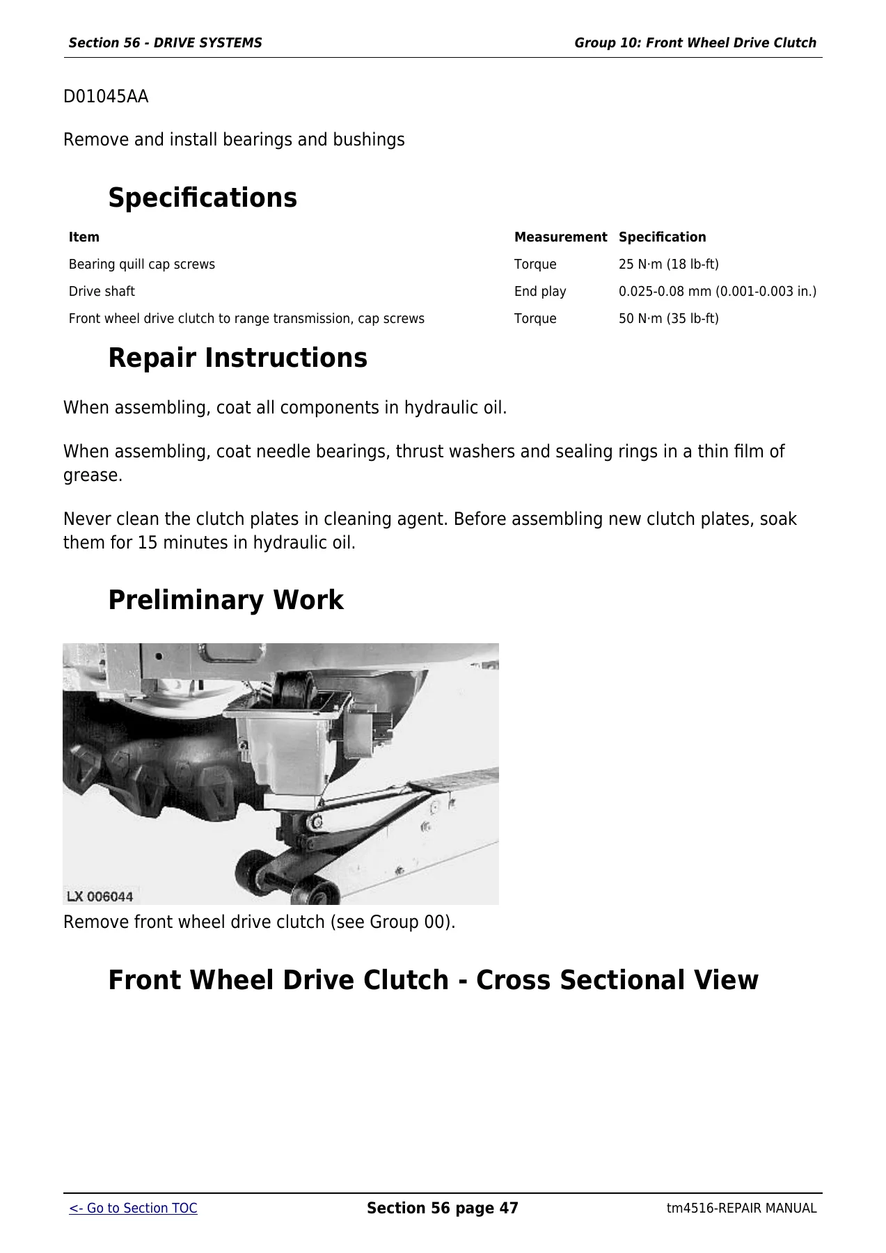
Specificationsp. 400
Repair Instructionsp. 400
Preliminary Workp. 400
Front Wheel Drive Clutch – Cross Sectional Viewp. 400
Removing Clutchp. 402
Disassemble MFWD Clutchp. 405
Front Wheel Drive Clutch Componentsp. 407
Assembling Clutchp. 409
Installing Clutchp. 412
Adjusting End Playp. 416
Adjusting the Brake Bandp. 417
Final Assemblyp. 417
+Group 15 – Differentialp. 418
Special or Essential Toolsp. 418
Service Equipment and Toolsp. 418
Specificationsp. 419
Repair Instructionsp. 419
Preliminary Workp. 419
Removing the Differentialp. 420
Disassembling the Differentialp. 424
Exploded Viewp. 426
Assembling the Differentialp. 429
Installing the Differentialp. 431
Adjusting Differential Preloadp. 432
Adjusting Backlashp. 433
Final Assemblyp. 434
+Group 20 – Final Drivesp. 435
Special or Essential Toolsp. 435
Service Equipment and Toolsp. 436
Other Materialp. 437
Specificationsp. 437
Repair Instructionsp. 437
Preliminary Workp. 437
Final Drive-Cross-Sectional Viewp. 438
Disassemble Planet Pinion Carrierp. 441
Planet Pinion Carrier-Exploded Viewp. 442
Assemble Planet Pinion Carrierp. 444
Remove Axle Housingp. 445
Disassemble and Assemble Axle Housingp. 447
Disassemble and Assemble Axle Shaftp. 448
Install Axle Housingp. 450
Install Planet Pinion Carrier and Check Rolling Drag Torquep. 452
Final Assemblyp. 455
+Group 25 – Rear PTOp. 457
Special or Essential Toolsp. 457
Service Equipment and Toolsp. 458
Specificationsp. 459
Repair Instructionsp. 459
Repair PTOp. 459
PTO Clutch-Cross-Sectional Viewp. 461
Remove and Disassemble PTO Clutchp. 464
Assemble and Install PTO Clutchp. 467
Remove and Disassemble Countershaftp. 470
PTO Countershaft-Cross-Sectional Viewp. 471
Assemble and Installp. 474
Shiftable PTO Output Shaft-Cross-Sectional Viewp. 475
Remove and Disassemble Output Shaftp. 478
Assemble and Install PTO Output Shaftp. 481
Shiftable PTO Shifter – Exploded Viewp. 484
Remove PTO Shifterp. 485
Install PTO Shifterp. 488
Replace PTO Brakep. 489
Replacing Oil Seal on PTO Output Shaftp. 490
Remove Valve Housingp. 490
Disassemble and Assemble Valve Housingp. 491
Install Valve Housingp. 491
PTO Shifting Partsp. 492
Changing and Adjusting the Bowden Cablep. 494
Adjusting the Indicator Light Switchp. 495
+Group 30 – Front PTOp. 496
Special or Essential Toolsp. 496
Specificationsp. 496
Front PTO (Running Clockwise)p. 496
Front PTO (Running Counterclockwise)p. 497
Front PTO – Sectional Viewp. 498
Removing Front PTO Shaftp. 501
Disassembling Front PTO Shaftp. 502
PTO (Clockwise Running) – Exploded Viewp. 505
PTO (Counterclockwise Running) – Exploded Viewp. 506
PTO Clutch and Brake – Clockwise Running PTOp. 508
PTO Clutch and Brake – Counterclockwise Running PTOp. 510
Front PTO Housingp. 511
Assembling Front PTOp. 513
Determining Preload of Input Shaft and PTO Shaft Taper Roller Bearingsp. 517
Installing Front PTO Shaftp. 518
Repairing Solenoid Valvep. 519
Layout of Oil Linesp. 520
+Group 35 – Hydraulic Pump Drivep. 522
Special or Essential Toolsp. 522
Service Equipment and Toolsp. 522
Specificationsp. 523
Hydraulic Pump Drive-Cross-Sectional Viewp. 523
Remove and Disassemble Pump Drive Pinion Gearp. 525
Remove and Disassemble Pump Drive Gearp. 527
Assemble and Install Pump Drive Gearp. 529
Assemble and Install Pump Drive Pinionp. 532
+Group 40 – Front Implement Drivep. 535
Special or Essential Toolsp. 535
Specificationsp. 535
Exploded Viewp. 536
Replacing Damperp. 538
+Section 60 – STEERING AND BRAKESp. 542
+Group 05 – Hydrostatic Steeringp. 542
Special or Essential Toolsp. 542
Specificationsp. 544
Removing Steering Valvep. 545
Removing Steering Column and Steering Valvep. 547
Steering Valve- Exploded Viewp. 553
Repairing Steering Valvep. 555
Disassembling the Steering Valvep. 561
Exploded View of Steering Valvep. 565
Assembling the Steering Valvep. 567
Adjusting Double-Acting Shock Valvesp. 577
Steering Wheel and Steering Columnp. 578
Repairing the Steering Columnp. 580
Installing Steering Valvep. 581
Installing Steering Column and Steering Valvep. 583
+Group 10 – Brake Valvep. 589
Specificationsp. 589
Repair Instructionsp. 589
Removing Brake Valvep. 590
Repair Brake Valvep. 595
Installing Brake Valvep. 602
Adjusting the Stop Light Switchp. 605
+Group 15 – Rear Wheel Brakesp. 607
Specificationsp. 607
Preliminary Workp. 607
Removing the Rear Wheel Brakesp. 607
Rear Wheel Brakes – Exploded Viewp. 608
Repairing the Brakesp. 610
Installing the Rear Brakesp. 611
Final Assemblyp. 612
Bleeding the Brakesp. 614
Checking the Brakesp. 617
+Group 20 – Handbrakep. 618
Specificationsp. 618
Preliminary Workp. 618
Removing the Handbrakep. 619
Exploded View of Handbrake – 6800 Tractorp. 621
Exploded View of Handbrake – 6900 Tractorp. 622
Installing the Handbrakep. 624
Adjusting the Brake Bandp. 627
Final Assemblyp. 627
Handbrake Componentsp. 628
Replacing the Handbrake Cablep. 631
Adjusting the Handbrakep. 633
+Group 25 – Hydraulic Trailer Brakep. 634
Special or Essential Toolsp. 634
Specificationsp. 634
Replacing Trailer Brake Valvep. 635
Replacing the Check Valvep. 635
Bleeding Trailer Brake Valvep. 636
Checking Trailer Brake Valvep. 637
Cleaning Trailer Brake Valvep. 639
Cleaning Sievep. 640
+Group 30 – Air Brakesp. 642
Special or Essential Toolsp. 642
Specificationsp. 643
General Informationp. 643
Installing the Screw Unionsp. 643
Changing the Compressorp. 645
Changing the Compressed Air Tankp. 646
Changing the Pressure Control Valvep. 647
Changing the Pressure-Limiting Valvep. 649
Changing the Trailer Control Valvep. 650
Changing the Pressure Gaugep. 652
Changing the Coupling Endsp. 653
Visual and Operational Checksp. 654
Leak Testp. 655
Checking the Handbrake (Dual-Line Brakes)p. 655
Checking the Handbrake (Single-Line Brakes)p. 656
Adjusting the Handbrakep. 657
Checking the ‘Supply” Coupling Endp. 657
+Section 70 – HYDRAULIC SYSTEMp. 661
+Group 05 – Controlsp. 661
General Informationp. 661
Connecting Bowden Cablep. 661
SCV Actuating Elementsp. 662
Adjusting Bowden Cablep. 664
Installing Multi-Function Leverp. 665
Adjusting Multi-Function Leverp. 667
+Group 10 – Hydraulic Pump and Charge Pumpp. 669
Service Equipment and Toolsp. 669
Other Materialp. 670
Specificationsp. 671
Repair Instructionsp. 671
Removing Charge Pumpp. 672
Disassembling Charge Pumpp. 672
Assembling Charge Pumpp. 674
Installing Charge Pumpp. 675
Checking Lube Oil Valvep. 675
Restrictor in Oil Tankp. 676
Check Valve in Oil Leak-Off Linep. 676
Changing the Hydraulic Pump Controllerp. 678
Hydraulic Pump Controller-Exploded Viewp. 679
Disassemble, Inspect, and Assemble Hydraulic Controllerp. 681
Adjusting the Controllerp. 682
Removing the Hydraulic Pumpp. 685
Installing the Hydraulic Pumpp. 687
Hydraulic Pump 40 cm3 (2.4 cu.in) – Exploded Viewp. 688
Hydraulic Pump 25 cm3 (1.5 cu.in) – Exploded Viewp. 691
Disassemble, Inspect and Assemble Hydraulic Pumpp. 694
Adjust Swashplate Bearing Preloadp. 700
Adjust Shaft Bearing Preload-40 cm 3 (2.4 cu.in) Pumpp. 703
+Group 15 – Valvesp. 705
Special or Essential Toolsp. 705
Special Tools (Dealer Fabricated)p. 705
Specificationsp. 707
Repair Instructionsp. 707
Direct Control of Rockshaftp. 708
Removing the Rockshaft Valvep. 708
Repairing Rockshaft Valvep. 710
Depth to Which Pressure and Discharge Valves are Screwed Inp. 714
Changing the Stepper Motorp. 714
Centering the Stepper Motorp. 715
Installing the Rockshaft Valvep. 717
Installing Shuttle Valvesp. 718
Repairing the Inlet Priority Valve – Exploded Viewp. 720
Removing the Inlet Priority Valvep. 722
Installing the Inlet Priority Valvep. 723
Checking Oil Filter Headp. 724
Filter Relief Valvep. 724
Power Beyond Application Valve – Exploded View (New Version)p. 726
Power Beyond Application Valve – Exploded View (Old Version)p. 728
Connecting the Power Beyond Application Valvep. 730
Adjusting the Power Beyond Application Valvep. 732
Converting the Power Beyond Application Valvep. 734
Connecting the Power Beyond Application Valvep. 736
Adjusting the Power Beyond Application Valvep. 738
+Group 20 – Three-Point Hitchp. 740
Other Materialp. 740
Specificationsp. 740
Changing the Position Sensorp. 740
Draft Sensor and Draft Link Support – Exploded Viewp. 740
Changing the Draft Sensor and Draft Link Supportp. 743
Removing and Installing the Lift Cylindersp. 745
Cross-Section and Exploded View – Lift Cylinderp. 746
Replacing the Bushings on the Rockshaft Housingp. 748
Automatic Stabilizer Rod (Left-Hand)p. 749
Adjustable Stabilizer Rod (Left or Right)p. 749
Adjustable Stabilizer Rod (Right-Hand)p. 750
+Group 25 – Selective Control Valves and Couplersp. 752
Special Tools (Dealer Fabricated)p. 752
Other Materialp. 752
Specificationsp. 753
Repair Instructionsp. 753
SCV Identificationp. 754
Removing Selective Control Valvesp. 754
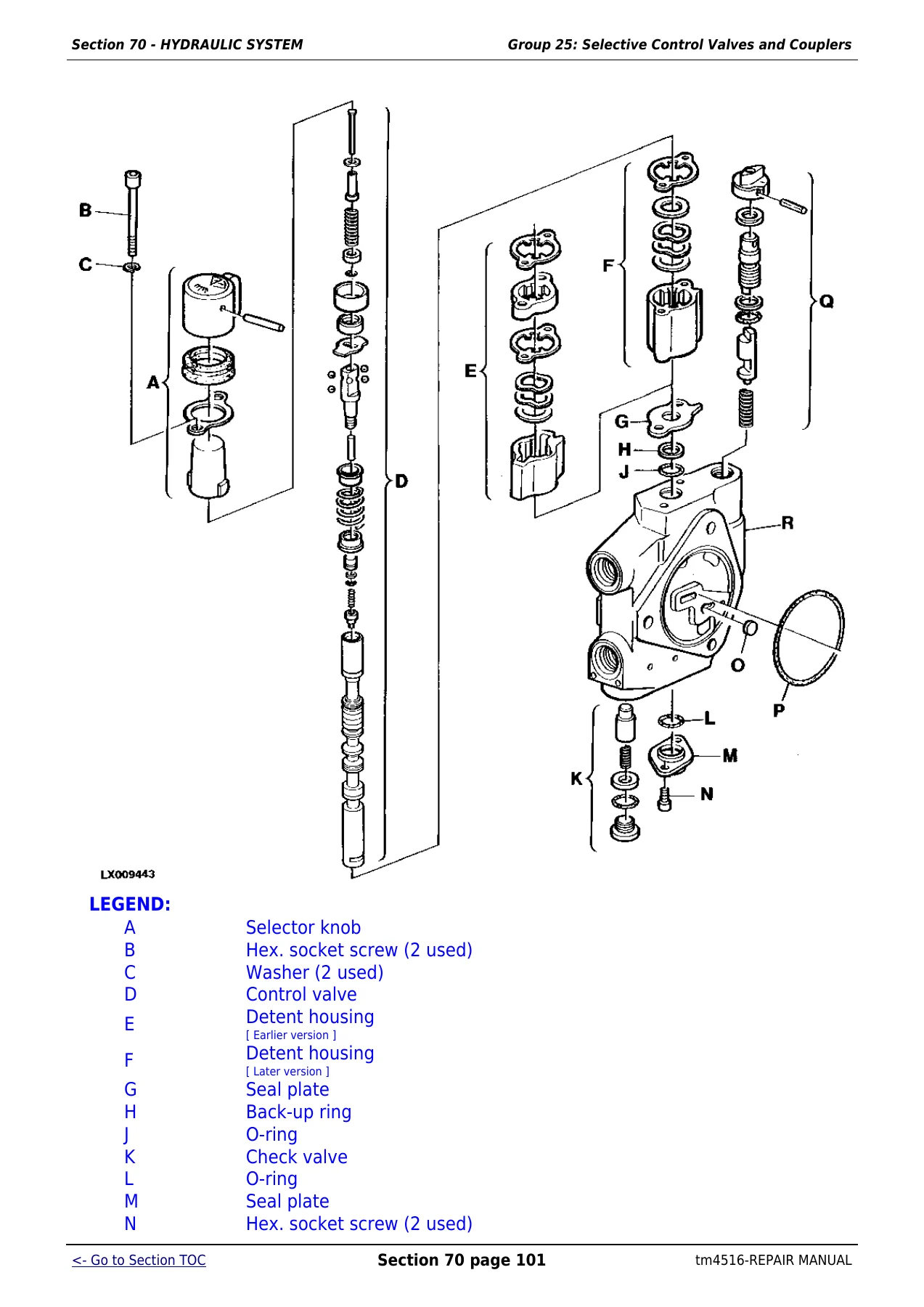
Series 100 Selective Control Valve – Exploded Viewp. 755
Disassemble, Inspect and Assemble the Control Valve-Series 100p. 758
Series 200 Selective Control Valve-Exploded Viewp. 760
Series 300 Selective Control Valve-Exploded Viewp. 762
Replace Control Knobsp. 763
Inspect Poppet Load-Check Valvesp. 764
Inspect Pressure Compensator Valve-300 Seriesp. 765
Inspect Metering Valve-Three-Position SCVp. 765
Inspect Metering Valve-200 Seriesp. 767
Disassemble, Inspect, and Assemble Control Valve-300 Seriesp. 769
Disassemble, Inspect, and Assemble Control Valve-200 Seriesp. 777
Installing Selective Control Valvesp. 782
Installing Shuttle Valvesp. 783
Installing the Endplatep. 785
Adjustment of Pressure Limit at Selective Control Valves (300 Series)p. 786
Changing Couplersp. 788
Deluxe Coupler – Exploded Viewp. 788
Repairing the Deluxe Couplerp. 791
Checking Couplers for Leaksp. 793
+Section 80 – MISCELLANEOUSp. 795
+Group 00 – Component Removal and Installationp. 795
Special or Essential Toolsp. 795
Specificationsp. 798
Removing Main Frame Halvesp. 799
Installing Main Frame Halvesp. 806
Removing Front Wheel Drive Axlep. 809
Installing Front Wheel Drive Axlep. 810
Removing Front Axle Supportp. 812
Installing Front Axle Supportp. 816
+Group 05 – Main Framep. 819
Specificationsp. 819
Removing and Installing the Main Framep. 819
+Group 10 – Front and Rear Wheelsp. 820
Special or Essential Toolsp. 820
Specificationsp. 820
Removing a Wheel (Front or Rear)p. 820
Attaching the Front Wheelsp. 821
Attaching the Rear Wheelsp. 821
+Group 15 – Trailer Hitchp. 823
Specificationsp. 823
Installing the Trailer Mountingp. 823
Installing the Guide Railsp. 823
Trailer Mounting (Height-Adjustable, 4-Position)p. 824
Trailer Mounting (Height-Adjustable, 9-Position)p. 825
Repairing the Automatic Trailer Hitchp. 827
Remote Control for Automatic Trailer Hitchp. 832
Adjusting the Remote Controlp. 834
Functional Checkp. 836
+Group 20 – Pick-Up Hitchp. 838
Specificationsp. 838
Installing Upper Framep. 838
Frame Assembly – Exploded Viewp. 838
Operating Lever and Lift Links – Exploded Viewp. 840
Hydraulic Partsp. 842
Repairing Hydraulic Cylinderp. 845
Adjusting Lift Linksp. 846
Adjusting Guide Stopp. 847
Changing the Bowden Cablep. 848
Adjusting the Bowden Cablep. 848
Operational Checkp. 849
+Group 25 – Swinging Drawbarp. 851
Torques for Hardware – Swinging Drawbarp. 851
Torques for Hardware – Swinging Drawbar with Pick-Up Trailer Hitchp. 851
+Section 90 – OPERATOR′S CAB AND 4-POST ROPSp. 855
+Group 00 – Tilting or Removing/Installing Operator′s Cabp. 855
Special or Essential Toolsp. 855
Specificationsp. 857
Tilting the Cab Upwardp. 858
Tilting the Cab Downwardp. 869
Removing the Operator′s Cabp. 873
Installing Operator′s Cabp. 880
+Group 05 – Controls and Instrumentsp. 885
Disconnecting Electrical Circuitp. 885
Specificationsp. 885
Removing Instrument Unitp. 885
Replacing Bulbsp. 886
Removing the Control Panelp. 887
Replacing a Bulbp. 887
Adjusting Digital Controlp. 889
Adjusting Analog Controlp. 891
Removing Multi-Function Unitp. 893
Replacing Multi-Function Unit Componentsp. 893
Installing Steering Wheelp. 895
Replacing Basic Control Modulep. 895
+Group 10 – Electronic Hitch Control Componentsp. 897
Disconnecting Electrical Circuitp. 897
Replacing Electronic Control Unitp. 897
Activating Quick-Lower or Hitch Dampening Functionsp. 899
Replacing Operation Unitp. 900
+Group 15 – Air Conditioning Systemp. 902
Special or Essential Toolsp. 902
Specificationsp. 909
Safety at Workp. 910
Handling Refrigerantp. 910
In an Emergencyp. 911
Safety Equipmentp. 911
Storage of Refrigerant Containersp. 912
R134A Refrigerantp. 912
Discharging the Systemp. 913
Evacuating the Systemp. 915
Filling With Refrigerant Oilp. 917
Filling the Systemp. 919
Topping Up a Partly Discharged Systemp. 921
Leak Testp. 922
Removing the Compressorp. 922
Checking Level in the Compressorp. 923
Disassembling the Compressor Clutchp. 924
Checking Clutch Hub Clearancep. 925
Checking the Compressor Manifoldp. 926
Installing the Compressorp. 927
Removing and Installing the Condenserp. 927
Removing and Installing the Receiver-Drierp. 928
Removing and Installing the Evaporator and Expansion Valvep. 929
Installing Condensation Water Drain Hosesp. 930
Removing and Installing the Thermostat Switchp. 931
Removing and and Installing the High/Low Pressure Switchp. 932
+Group 20 – Heating Systemp. 934
Ventilator and Heater, Exploded Viewp. 934
Removing and Installing Fan and Radiatorp. 935
Removing and Installing Heating Regulatorp. 936
Removing the Air Filterp. 937
+Group 25 – Operator′ Cabp. 939
Specificationsp. 939
Removing Cab Framep. 939
Removing and Installing Mounting Bracketsp. 940
Installing Windshieldp. 942
Installing Rear Windowp. 942
Adjusting Window Contact Pressurep. 943
Removing Cab Doorp. 944
Installing Cab Doorp. 944
Installing Door Lockp. 944
Installing Door Holding Bracketp. 946
Replacing Handrail or Rear View Mirrorp. 946
Removing Hatchp. 947
Removing Outer Roofp. 948
Removing Inner Roofp. 950
Installing Inner Roofp. 952
+Group 30 – Seatsp. 953
Specificationsp. 953
Comfort Seat DS44-07, Exploded Viewp. 954
Comfort Seat DS44-06, Exploded Viewp. 956
Super Comfort Seat S85/90-05, Exploded View – Upper Sectionp. 958
Super Comfort Seat DS85H1-02, Exploded View – Lower Sectionp. 961
Air Comfort Seat MSG95A-00, Lower Sectionp. 964
Passenger Seat, Exploded Viewp. 971
+Group 35 – Radio Installationp. 973
Radio, Loudspeakers and Aerial, Exploded Viewp. 973
+Section 99 – SPECIAL TOOLS (DEALER-FABRICATED)p. 976
+Group 05 – Special Tools (Dealer-Fabricated)p. 976
DFRW29-Final Drive Housing Adapterp. 976
DFRW30-Axle Jacking Toolp. 976
DFRW79-Piston Holding Toolp. 977
Holding Devicep. 978
Shifter Rail Detent Holding Toolp. 978
Socket Wrench Insertp. 979
Suspension Eyes for Operator′s Cabp. 979
This is a genuinely comprehensive shop-level document. It addresses both the 6800 and 6900 as distinct machines — specifications, capacities, and torque values are presented side by side wherever the two models differ — giving a technician a precise, model-specific reference rather than a generic guide. Each section opens with its own essential tools list, service specifications, and wear tolerances before stepping through disassembly, inspection, and reassembly procedures. The coverage of the PowrQuad transmission alone spans multiple groups, with detailed procedures for the module, range box, creeper unit, and reverser. The hydraulic section extends from the axial-piston pump and its load-sensing controller through every valve assembly, the three-point rockshaft, and the selective control valves. For a machine that ties hydraulics, electronics, and mechanical drive systems this closely together, having all sections under one document is particularly practical.
What the Engine Specifications Tell You
The 6800 carries a 6068TL001 turbocharged six-cylinder engine rated at 88 kW (120 hp) with 536 N·m (395 lb-ft) of peak torque at 1300 rpm. The 6900 steps up to the 6068TL002, rated at 96 kW (130 hp) with 595 N·m (439 lb-ft) at the same engine speed. Both share identical bore (106.5 mm), stroke (127.0 mm), and displacement (6790 cm³). The manual provides valve clearances, idle speed settings, fuel system type (direct injection, distributor pump), and firing order — all the information needed to properly set up or diagnose the engine without referencing a separate engine-specific publication.
Transmission and Drivetrain Depth
The PowrQuad is a synchronized automatic transmission that shifts four gears mechanically-hydraulically under load without operating the clutch. Tractors are covered in both 30 km/h and 40 km/h variants (4-range and 5-range respectively), and the creeper transmission — a non-synchronized reduction gear cutting ground speed by approximately 90% — is also included. Front wheel drive operates via a hydraulically controlled wet disc clutch, and the differential lock is electro-hydraulic. Final drives use planetary reduction gearing. The John Deere 6800 6900 Tractors Repair Manual TM4516 covers removal, overhaul, and reassembly of every component in this chain, with torque specifications at each fastening point.
Hydraulic System Coverage
The hydraulic system runs as a closed-centre load-sensing arrangement. Standby pressure is 3000 kPa (30 bar; 435 psi) and maximum system pressure is 20000 kPa (200 bar; 2900 psi). The axial-piston pump is pressure and flow compensated; the manual includes full controller adjustment procedures for both the compensating valve and the load-sensing valve. Three-point hitch control is electronic-hydraulic via stepper motor and valve. Selective control valve groups are covered in detail, including exploded views and spring specifications for the Series 200 SCV.
Work This Manual Supports
The John Deere 6800 6900 Repair Manual TM4516 supports the full scope of dealer-level repair work on these tractors: engine pull and reinstall, full PowrQuad module overhaul, front wheel drive clutch rebuild, differential and final drive service, hydrostatic steering valve repair, hydraulic pump and controller overhaul, three-point hitch valve servicing, wiring harness diagnosis and connector repair, air conditioning service (R134a), and cab removal and reinstallation. Every group carries the specific torque values, clearances, and wear tolerances needed to reassemble to specification — not just to hand-tight.
Getting procedures from the right source matters when torque values, clearance tolerances, and assembly sequences are system-specific. This TM4516 repair manual for the John Deere 6800 and 6900 provides those values directly from the documentation produced for these tractors. Purchase delivers an instant PDF download — no shipping wait, accessible on any device, and printable to keep in the shop alongside the machine.

Reviews
There are no reviews yet.