
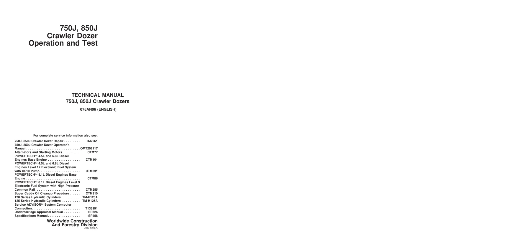
John Deere 750J 850J Crawler Dozer Operation and Test Manual TM2260 – PDF
Original price was: $67.95.$41.95Current price is: $41.95.
The complete TM2260 Operation and Test manual for John Deere 750J and 850J Crawler Dozers – 516 pages of diagnostic procedures, hydraulic and hydrostatic test values, electrical schematics, DTCs, and system theory in one downloadable PDF.
Description
This is the John Deere 750J 850J Crawler Dozer Operation and Test Technical Manual TM2260 – the diagnostic and testing companion volume that Deere service technicians use to isolate problems, run operational checks, and verify system performance on both the 750J and 850J crawler dozers. Published 07JAN06 by Deere & Company’s Worldwide Construction And Forestry Division, it covers the POWERTECH 6.8L (6068) and 8.1L (6081) diesel engine platforms used across the two models, along with the electrical, hydraulic, hydrostatic, and HVAC systems that surround them. If you service, diagnose, or own one of these crawlers, this is the book that takes you from a complaint to a confirmed test result before a component comes off the machine.
File Details
- Manual Type: Operation and Test Technical Manual (TM2260)
- Brand: John Deere
- Models Covered: 750J, 850J Crawler Dozers
- Language: English
- Page Count: 516 pages
- File Format: PDF
- Document Number: TM2260
- Publication Date: 07JAN06 (January 7, 2006)
- Publisher: Deere & Company, Worldwide Construction And Forestry Division
- Copyright: 2006 Deere & Company
Chapters Covered
The manual is divided into seven top-level sections, each broken down into Theory of Operation, Diagnostic Information, and Tests where applicable:
- Section 9000 – General Information
- Section 9005 – Operational Checkout Procedure
- Section 9010 – Engine
- Section 9015 – Electrical System
- Section 9025 – Hydraulics
- Section 9026 – Hydrostatic System
- Section 9031 – Heating and Air Conditioning
Section 9000 – General Information
Group 01 covers safety for the technician working around the machine: recognizing safety alert symbols, working safely around high-pressure hydraulic fluid, handling batteries and exhaust fumes, preparing the machine for service, and the warnings that appear on the machine and in the manual. Short, but the kind of chapter that keeps a shop out of trouble.
Section 9005 – Operational Checkout Procedure
Group 10 is a structured walk-around and seat-based inspection sequence. The chapter splits into Engine Off Checks and Engine On Checks. Off checks cover DTC viewing and clearing through the CAN Monitor Unit (CMU) or SERVICE ADVISOR, radiator cap and coolant condition, start aid canister and line routing, final fuel filter bleed, water separator drain, grouser wear, track sag and roller/idler leakage, battery disconnect switch, fuel cap, cab door and window seals, horn, seat controls, reverse warning alarm, wipers and washers, battery voltage, and monitor display behavior. Engine On checks cover pilot controller lock and unlock behavior, blade float detent, pilot controller lever positions, transmission speed default to 1.6, quick-drop valve timing on outside dozers, slow and fast idle readings, air conditioner operation, alternator, air restriction indicator, decelerator/brake pedal and park brake, park brake valve leakage, reversing fan, and cylinder cycle times with the published specifications for 750J OSD, 750J PAT, 850J OSD, and 850J PAT. This is the chapter you use when a machine comes in with a complaint and you need to reproduce it before you open a wrench drawer.
Section 9010 – Engine
Group 05 covers the POWERTECH 6.8L (6068) and 8.1L (6081) John Deere engines, with cross-references to the deeper CTM base-engine and fuel-system manuals. Group 15 provides diagnostic entry points into engine symptoms – black or gray smoke, no-crank, poor idle, abnormal noise, excessive fuel consumption – mapped to the relevant CTM section for the 750J’s Level 12 electronic fuel system with DE10 pump or the 850J’s Level 9 system with Denso high-pressure common rail. Group 25 gives you the actual tests: intake manifold pressure (turbocharger boost) with the 750J and 850J specifications, and fuel supply pump pressure with the 750J and 850J values and test-port connection procedure.
Section 9015 – Electrical System
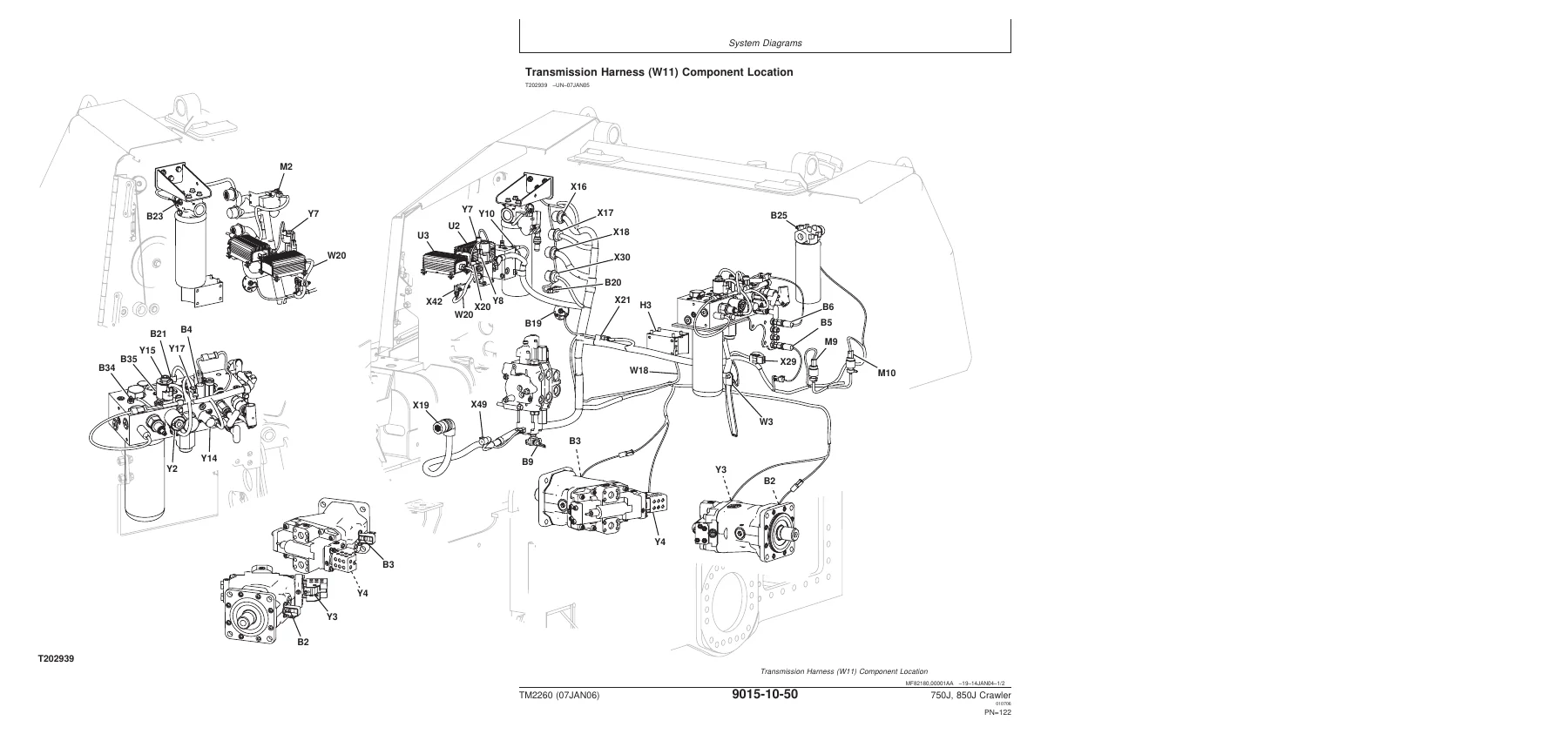
Group 05 covers electrical diagram information and how to read the schematics, wiring diagrams, and component location legend. Group 10 is the heavy diagram set: fuse and relay specifications for the Vehicle Electrical Center (VEC), system functional schematics with wiring diagrams for the operator’s station harness (W7), canopy roof (W8), cab roof (W9), engine (W10), transmission (W11), air conditioning (W14), and radio (W15). Group 15 has the theory of operation for the starting and charging circuit, the Controller Area Network (CAN), the Engine Control Unit (ECU), the Transmission Control Unit (TCU), and the CAN Monitor Unit (CMU). Group 20 is the reference chapter – Diagnostic Trouble Code quick reference lists for the TCU, ECU (750J and 850J separate), and CMU, plus the alternator test procedure, electrical component specifications, TCU calibration, wire harness test procedure, decelerator/brake pedal adjustment, engine speed control switch and rotary sensor remove and install, TCL adjustment, and connector replacement and installation procedures for WEATHER PACK, DEUTSCH, CINCH, and Metri-Pack connectors.
Section 9025 – Hydraulics
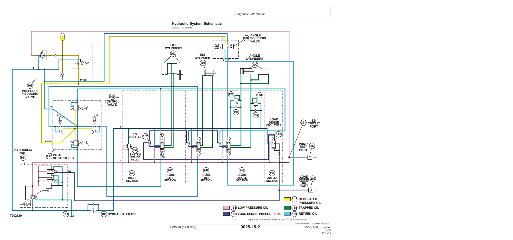
Group 05 is the theory chapter for the closed-center load-sensing hydraulic system: how the variable-displacement axial-piston pump goes onto stroke, the control valve inlet section, load sense circuit, load sense isolator, circuit relief valve with anticavitation, system relief valve, hydraulic oil filter manifold, blade angle operation, ripper operation, and quick-drop valve operation. Group 15 provides the full hydraulic schematic for PAT and OSD configurations (with and without winch and ripper), main and ripper-ready component locations, and a symptom-based diagnostic table for no functions, slow functions, noisy pump, blade float that does not work, single function failure, low power, drift down, oil overheating, and foaming oil. Group 25 walks through the pressure, flow, drift, leakage, and adjustment tests: system relief valve, circuit relief valve, pump load sense differential and system pressure, lift and tilt cylinder drift, cylinder leakage, pressure reducing valve, blade down accumulator discharge and precharge, pump flow, and pump case drain.
Section 9026 – Hydrostatic System
Group 05 is the theory chapter for the automatic, dual-path hydrostatic drive: transmission control flow chart, charge pump operation, hydrostatic charge oil filter, neutral charge relief, multi-function valve, HIC valve, park brake valve, oil cooler and reservoir bypass, PCP operation, PDCV operation, hydrostatic pump and motor operation, flushing and operating charge relief, and the hydraulic fan drive and return filter. Group 15 provides the flowcharts that working techs actually use: overheating, low charge pressure, mistrack/index, machine will not reach full speed, low power, one or both tracks will not move, and TCU calibration problems. Component locations and the neutral, forward, and reverse system diagrams round it out. Group 25 gives you the measurement procedures: transmission oil warm-up, park brake release for towing, hydrostatic pump and motor initial start-up, flushing, PCP manual override and PCP test, PCP internal adjustment, multi-function relief valve test, transmission efficiency test, neutral and operating charge relief pressure test, PDCV neutral adjustment, pump servo pressure test, MDCV adjustment, motor min/max angle servo piston pressure test, charge pump flow test, oil cooler and reservoir bypass tests, park brake test and relief valve test, cab tilt relief valve test, hand pump bleed, fan pump pressure and flow, fan motor speed, and fan motor case drain.
Section 9031 – Heating and Air Conditioning
Group 05 explains the R134a air conditioning cycle from compressor to evaporator and back, including the receiver-dryer, expansion valve, freeze control switch, high and low pressure switches, and accumulator. Group 15 covers HVAC diagnostics: air conditioning not operating, not cooling, running too cold or constantly, and heater problems. Group 25 covers proper refrigerant handling, R134a cautions, oil and refrigerant charge capacities, hose and tubing inspection, the R134a system test, an operating pressure diagnostic chart keyed to ambient temperature, low and high pressure switch tests, freeze control switch test, and leak testing.
Who This Manual Is For
The 750J and 850J are working crawlers, and the people who keep them working – independent shops, dealer techs, fleet maintenance departments, and owner-operators with a service pit – need more than a parts diagram. This manual supports the full diagnostic loop. You get the operational checkout to reproduce the complaint, the theory to understand what the machine is supposed to be doing, the DTC lists to read what the controllers are complaining about, the schematics to trace the wiring or the hydraulic circuit, and the test procedures with real values to confirm the diagnosis before you pull a component. The engine, electrical, hydraulic, hydrostatic, and HVAC systems are all in one volume, so you are not juggling five separate books to chase a single fault.
Why a Correct Test Value Matters
Hydrostatic crawler diagnostics are not guesswork-friendly. The manual publishes load sense differential pressures of 1620-1827 kPa (16.2-18.3 bar) for the 750J and 1793-2000 kPa (17.9-20 bar) for the 850J, system relief at 28 269-28 786 kPa (282.7-287.9 bar), multi-function relief at 44 128-46 884 kPa (441-468 bar), and a whole table of PCP output currents and pressures used to confirm whether the pump control is doing what the controller asked. Electrical tests reference specific voltage windows like 4.75-5.25 V sensor supply, 0.11-1.10 V or 3.90-4.85 V for motor speed sensors, and 24 V system checks. The Operational Checkout alone lists cycle times for blade raise, power down, tilt left/right, and angle left/right across four machine configurations. Without the book, those numbers come from memory or from a forum post – and a hydrostatic pump replaced on a bad guess is an expensive way to learn.
IMAGES PREVIEW
Instant PDF Delivery, No Shipping
This is a downloadable PDF of the complete TM2260. It arrives the moment payment clears – no waiting on a mail carrier, no binder to lose, no shipping charge. Open it on a laptop in the shop office, on a tablet at the machine, or print the pages you need for the job and keep the dirty ones in the toolbox. Either way, the full manual is on hand the next time a 750J or 850J comes in with a complaint.

Reviews
There are no reviews yet.