Description
File Details
- Manual Type: Repair Technical Manual
- Model: John Deere 848H Skidder
- Document Number: TM10289
- Date: 27 August 2009
- Language: English
- Page Count: 546 pages
- File Format: PDF
- Publisher: Deere & Company, Worldwide Construction and Forestry Division — Litho in U.S.A.
- Previous Editions: Copyright 2007, 2008, 2009
Chapters Covered
- Section 00 — General Information
- Group 0001: Safety Information
- Group 0003: Torque Values (Metric and Unified Inch bolt/cap screw charts, fitting service recommendations)
- Section 01 — Wheels
- Group 110: Powered Wheels and Fastenings
- Section 02 — Axle
- Group 0200: Removal and Installation (TeamMate IV front and rear axles, differentials, oscillation supports)
- Group 0225: Input Drive Shafts and U-Joints
- Group 0260: Hydraulic System (Differential Lock Solenoid Valve)
- Section 03 — Transmission
- Group 0300: Removal and Installation
- Group 0315: Controls
- Group 0325: Input Drive Shafts and U-Joints
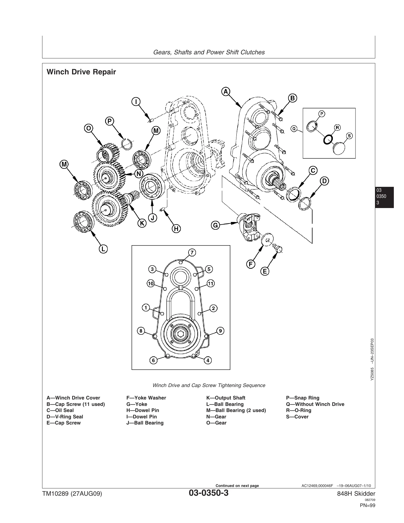
- Group 0350: Gears, Shafts and Power Shift Clutches (including Winch Drive Repair, Input Yoke)
- Group 0360: Hydraulic System (Transmission Charge Pump, Suction Tube, Control Valve)
- Section 04 — Engine
- Group 0400: Engine Removal and Installation
- Section 05 — Engine Auxiliary Systems
- Group 0505: Cold Weather Starting Aids
- Group 0510: Cooling Systems
- Group 0520: Intake System
- Group 0530: Exhaust System
- Group 0560: External Fuel Supply
- Section 06 — Torque Converter
- Group 0600: Remove and Install
- Group 0641: Torque Converter Housing Disassemble and Assemble
- Section 09 — Steering System
- Group 0930: Secondary Steering Pump
- Group 0960: Hydraulic System (Steering Valve Remove/Install/Disassemble/Assemble, Steering Cylinder)
- Group 0962: Dual Mode Steering Solenoid Valve
- Section 10 — Service Brakes
- Group 1015: Controls Linkage
- Group 1060: Hydraulic System
- Section 11 — Park Brake
- Group 1111: Active Elements
- Group 1160: Hydraulic System
- Section 17 — Frame, Chassis, and Supporting Structures
- Group 1740: Frame Installation
- Group 1746: Frame Bottom Guards
- Section 18 — Operator’s Station
- Group 1800: Removal and Installation (Cab, Cab Tilt Hand Pump, Cab Tilt Cylinder)
- Group 1810: Operator Enclosure (Windows)
- Group 1821: Seat and Seat Belt
- Group 1830: Heating and Air Conditioning
- Section 19 — Sheet Metal and Styling
- Group 1910: Hood/Engine Enclosure
- Section 20 — Safety, Convenience, and Miscellaneous
- Group 2003: Pressurized Water System
- Group 2004: Horn and Warning Devices
- Section 21 — Main Hydraulic System
- Group 2160: Hydraulic System (Hydraulic Pump, Reservoir)
- Section 30 — Winch
- Group 3000: Removal and Installation (40/4000 and 60/6000 Series Winches)
- Group 3015: Controls Linkage
- Group 3025: Input Drive Shafts and U-Joints
- Group 3050: Drive and Clutch
- Section 32 — Stacking Blades
- Group 3201: Blades
- Group 3215: Controls Linkage
- Group 3260: Hydraulic System
- Section 38 — Grapple
- Group 3803: Grapple Mechanism (Damper, Damper Adjustment, Yoke, Crosshead)
- Group 3815: Controls Linkage
- Group 3840: Frames
- Group 3860: Hydraulic System
- Section 99 — Dealer Fabricated Tools
- Group 9900: Dealer Fabricated Tools
Complete PDF Bookmark Tree
Complete Bookmarks
The complete bookmarks in the “John Deere 848H Skidder Repair Technical Manual TM10289 PDF Download” are as follows:
+Contentsp. 5
+General Informationp. 9
+Safety Informationp. 11
Recognize Safety Informationp. 11
Follow Safety Instructionsp. 11
Operate Only If Qualifiedp. 11
Wear Protective Equipmentp. 12
Avoid Unauthorized Machine Modificationsp. 12
Inspect Machinep. 12
Stay Clear of Moving Partsp. 13
Avoid High-Pressure Oilsp. 13
Avoid High-Pressure Fluidsp. 14
Do Not Use Starting Fluidp. 14
Beware of Exhaust Fumesp. 14
Prevent Firesp. 15
Prevent Battery Explosionsp. 15
Handle Chemical Products Safelyp. 16
Dispose of Waste Properlyp. 16
Prepare for Emergenciesp. 16
Use Steps and Handholds Correctlyp. 17
Start Only From Operator's Seatp. 17
Use and Maintain Seat Beltp. 17
Prevent Unintended Machine Movementp. 18
Avoid Work Site Hazardsp. 18
Operate Machine Safelyp. 19
Keep Riders Off Machinep. 19
Avoid Backover Accidentsp. 20
Avoid Machine Tip Overp. 20
Operating on Slopesp. 21
Operating or Traveling On Public Roadsp. 21
Inspect and Maintain ROPSp. 21
Keep the Operator Protective Structure (OPS) in Placep. 22
Add and Operate Attachments Safelyp. 22
Park and Prepare for Service Safelyp. 23
Service Cooling System Safelyp. 23
Remove Paint Before Welding or Heatingp. 24
Make Welding Repairs Safelyp. 24
Drive Metal Pins Safelyp. 25
+Torque Valuesp. 27
Hardware Torque Specificationsp. 27
Keeping ROPS Installed Properlyp. 27
+Torque Valuep. 28
Metric Bolt and Cap Screwp. 28
Additional Metric Cap Screw Torque Valuesp. 29
+Torque Valuep. 31
Unified Inch Bolt and Cap Screwp. 31
Check Oil Lines And Fittingsp. 32
Service Recommendations for 37° Flare and 30° Cone Seat Connectorsp. 33
Service Recommendations for O-Ring Boss Fittingsp. 34
Service Recommendations For Flat Face O-Ring Seal Fittingsp. 36
Service Recommendations for Metric Series Four Bolt Flange Fittingp. 37
Service Recommendations For Inch Series Four Bolt Flange Fittingsp. 38
+Wheelsp. 39
+Powered Wheels and Fasteningsp. 41
Wheel Remove and Installp. 41
Tire Remove and Installp. 43
Dual Wheel Installationp. 45
+Axlep. 47
+Removal and Installationp. 49
TeamMate™ IV Axlesp. 49
Front Axle, Differential, and Oscillation Supports Remove and Installp. 50
Rear Axle and Differential Remove and Installp. 57
Front Axle Guards Remove and Installp. 62
Oscillation Supports Repairp. 63
+Input Drive Shafts and U-Jointsp. 65
Front Axle Drive Shaft Remove and Installp. 65
Rear Axle and Transmission Drive Shaft Remove and Installp. 68
+Hydraulic Systemp. 73
Differential Lock Solenoid Valve Repairp. 73
+Transmissionp. 77
+Removal and Installationp. 79
Transmission Remove and Installp. 79
Transmission Mount Remove and Installp. 92
+Controlsp. 93
Transmission Bump Shifter Remove and Installp. 93
+Input Drive Shafts and U-Jointsp. 95
Engine-to-Transmission Drive Shaft Remove and Installp. 95
+Gears, Shafts and Power Shift Clutchesp. 99
Transmission Repair Proceduresp. 99
Winch Drive Repairp. 101
Input Yoke Remove and Installp. 106
+Hydraulic Systemp. 109
Transmission Charge Pump Remove and Installp. 109
Transmission Suction Tube Repairp. 112
Transmission Control Valve Repairp. 113
+Enginep. 123
+Removal and Installationp. 125
6068 John Deere Engine POWERTECH® 6.8 L Diesel Engines—Base Engine—Use CTM104p. 125
6068 John Deere Engine POWERTECH® 6.8 L—Level 14 Electronic Fuel System With Denso HPCR—Use CTM320 Repairsp. 125
Engine Removalp. 126
Engine Installationp. 137
+Engine Auxiliary Systemsp. 143
+Cold Weather Starting Aidsp. 145
Do Not Use Ether Start Aidp. 145
+Cooling Systemsp. 147
Fan Guards Remove and Installp. 147
Belt Remove and Installp. 148
Belt Tensioner—Spring Tension Checkp. 149
Belt Tensioner Remove and Installp. 150
Aftercooler Remove and Installp. 150
Radiator Remove and Installp. 154
Transmission Cooler Remove and Installp. 157
Hydraulic Oil Cooler Remove and Installp. 160
Fan Shroud Remove and Installp. 161
+Intake Systemp. 163
Air Cleaner Remove and Installp. 163
+Exhaust Systemp. 165
Muffler Remove and Installp. 165
+External Fuel Supplyp. 167
Fuel Tank Remove and Install—Grapple Skidderp. 167
+Torque Converterp. 171
+Remove and Installp. 173
Torque Converter Housing Remove and Installp. 173
+Torque Converter Housingp. 183
Torque Converter and Torque Converter Housing Disassemble and Assemblep. 183
+Steering Systemp. 185
+Secondary Steeringp. 187
Secondary Steering Pump Remove and Installp. 187
+Hydraulic Systemp. 191
Steering Valve Remove and Installp. 191
Steering Valve Disassemble and Assemblep. 196
Steering Cylinder Remove and Installp. 201
+Dual Mode Steeringp. 205
Dual Mode Steering Solenoid Valve Remove and Installp. 205
+Service Brakesp. 207
+Controls Linkagep. 209
Service Brake Pedal Remove and Installp. 209
+Hydraulic Systemp. 211
Service Brake Valve Remove and Installp. 211
Service Brake Valve Disassemble and Assemblep. 214
Service Brake Accumulator Remove and Installp. 215
+Park Brakep. 219
+Active Elementsp. 221
Park Brake Remove and Installp. 221
+Hydraulic Systemp. 225
Park Brake Solenoid Valve Repairp. 225
+Frame, Chassis, or Supporting Structuresp. 229
+Frame Installationp. 231
Welding Repair of Major Structurep. 231
Engine and Equipment Frames—Separatep. 232
Lower Pivot Pin Repairp. 238
Upper Pivot Pin Repairp. 246
+Frame Bottom Guardsp. 251
+Bottom Guardp. 251
Engine Framep. 251
Equipment Framep. 253
+Operator's Stationp. 255
+Removal and Installationp. 257
Cab Remove and Installp. 257
Cab Isolators Remove and Installp. 272
Steering Column and Steering Wheel Remove and Installp. 275
Steering Column and Steering Wheel Disassemble and Assemblep. 277
Cab Tilt Hand Pump Remove and Installp. 279
Cab Tilt Hand Pump Disassemble and Assemblep. 280
Cab Tilt Hand Pump Bleeding Procedurep. 282
Cab Tilt Cylinder Remove and Installp. 285
+Operator Enclosurep. 287
Window Remove and Installp. 287
Window Cleaning Procedurep. 290
Cab Door Remove and Installp. 290
Cab Door and Door Latch Disassemble and Assemblep. 292
Front Windshield Wiper Remove and Installp. 293
Rear Windshield Wiper Remove and Installp. 295
Windshield Wiper Adjustmentp. 298
+Seat and Seat Beltp. 301
Seat Remove and Installp. 301
Seat Disassemble and Assemblep. 303
Seat Belt Remove and Installp. 310
+Heating and Air Conditioningp. 311
Proper Refrigerant Handlingp. 311
+Air Conditioner Systemp. 313
+R134A Refrigerant Oilp. 316
+R134A Refrigerant Recovery, Recycling and Charging Stationp. 318
Installation Procedurep. 318
Recover R134a Refrigerantp. 319
Evacuate R134a Systemp. 320
Charge R134a Systemp. 321
Compressor Relief Valve Remove and Installp. 322
Refrigerant High/Low Pressure Switch Remove and Installp. 322
Air Conditioning Compressor Remove and Installp. 324
Air Conditioning Compressor Clutch Remove and Installp. 327
Air Conditioning Compressor Manifold Remove and Installp. 329
Air Conditioning Condenser Remove and Installp. 329
Evaporator Remove and Installp. 332
Expansion Valve Remove and Installp. 333
Blower Motor Remove and Installp. 335
Heater Core Remove and Installp. 337
Coolant Valve Remove and Installp. 338
Receiver Dryer Remove and Installp. 340
Freeze Control Switch Remove and Installp. 340
+Sheet Metal and Stylingp. 343
+Hood or Engine Enclosurep. 345
Hood Remove and Installp. 345
+Safety, Convenience, and Miscellaneousp. 351
+Pressurized Water Systemp. 353
Pressurized Water Systemp. 353
+Horn and Warning Devicesp. 355
Horn Remove and Installp. 355
Reverse Warning Alarm Remove and Installp. 355
+Main Hydraulic Systemp. 357
+Hydraulic Systemp. 359
Hydraulic Pump Remove and Installp. 359
Hydraulic Pump Disassemble and Assemblep. 364
Priority Valve Repairp. 376
Cold Start Dump Valve Remove and Install (If Equipped)p. 379
Fan Variable Speed and Reversing Manifold Remove and Installp. 381
Fan Variable Speed and Reversing Manifold Disassemble and Assemblep. 383
Hydraulic Fan Motor Remove and Installp. 386
Hydraulic Fan and Cooling Loop Pump Remove and Installp. 389
Hydraulic Reservoir Remove and Installp. 392
Hydraulic Oil Cleanup Procedure Using Portable Filter Caddyp. 400
+Winchp. 401
+Removal and Installationp. 403
Winch 4000 Series Remove and Installp. 403
Fastening Cable to Winch Drum—4000 Seriesp. 409
Winch Free Spool Drag Adjustmentp. 411
Winch 6000 Series Remove and Installp. 412
Fastening Cable to Winch Drum—6000 Seriesp. 416
+Controls Linkagep. 418
Winch Control Valve Linkage Remove and Installp. 418
Winch Control Cable Remove and Installp. 419
+Input Drive Shafts and U-Jointsp. 425
Winch Drive Shaft Remove and Installp. 425
Winch 4000 Series Drive Shaft Disassemble and Assemblep. 426
+Drive and Clutchp. 427
Winch 4000 Series Drive and Clutch Repairp. 427
Winch 6000 Series Drive and Clutch Repairp. 427
+Stacking Bladesp. 429
+Bladesp. 431
Stacking Blade Remove and Installp. 431
Spherical Bushing Remove and Installp. 436
+Controls Linkagep. 439
Blade Control Linkage Remove and Installp. 439
Blade Control Valve Remove and Installp. 440
+Hydraulic Systemp. 441
Blade Lift Cylinder Remove and Installp. 441
+Grapplep. 443
+Grapple Mechanismp. 445
Grapple Remove and Installp. 445
Grapple Disassemble and Assemblep. 447
Grapple Damper Repairp. 450
Grapple Damper Adjustmentp. 452
Dampener, Yoke, and Crosshead Pins Lubricatep. 454
Grapple Rotate Yoke Repairp. 455
+Controls Linkagep. 466
Single Lever Pilot Controller Remove and Installp. 466
+Framesp. 469
Dual Function Grapple Cable Rollers Remove and Installp. 469
Dual Function Grapple Boom Remove and Installp. 470
Dual Function Grapple Arch Remove and Installp. 472
+Hydraulic Systemp. 475
Boom or Arch Cylinder Remove and Install—Dual Function Grapplep. 475
Grapple Tong Cylinder Remove and Installp. 477
Grapple Rotate Motor Remove and Installp. 479
Grapple Rotate Motor Disassemblep. 484
Grapple Rotate Motor Assemblyp. 491
Rotate Motor Drive Gear Remove and Installp. 498
Control Valve Optionsp. 499
Pilot Operated Control Valve Remove and Installp. 500
Dual Function Pilot Operated Control Valve Disassemble and Assemblep. 504
Control Valve Relief Valves Remove and Installp. 507
Lift Check Valve Disassemble and Assemblep. 508
Non-adjustable Circuit Relief Valve Disassemble and Assemblep. 509
Adjustable Circuit Relief Valve Disassemble and Assemblep. 511
Spool Valve Disassemble and Assemblep. 513
Detent Disassemble and Assemblep. 514
Pilot Operated Valve Remove and Installp. 515
Solenoid Operated Valve Remove and Installp. 516
Grapple Rotate Solenoid Valve Remove and Installp. 518
+Grapple Rotate Solenoid Valvep. 519
Disassemble and Assemblep. 519
Flow Divider Repairp. 520
Rotary Manifold Remove and Installp. 524
Rotary Manifold Disassemble and Assemblep. 526
+Dealer Fabricated Toolsp. 531
+Dealer Fabricated Toolsp. 534
DFT1099 Bushing Driversp. 534
DFT1216 Converter Housing Supportp. 536
DFRW20 Compressor Holding Fixturep. 537
+Page Numbersp. 5
+Section 00p. 9
+Group 0001p. 11
1p. 11
2p. 12
3p. 13
4p. 14
5p. 15
6p. 16
7p. 17
8p. 18
9p. 19
10p. 20
11p. 21
12p. 22
13p. 23
14p. 24
15p. 25
16p. 26
+Group 0003p. 27
1p. 27
2p. 28
3p. 29
4p. 30
5p. 31
6p. 32
7p. 33
8p. 34
9p. 35
10p. 36
11p. 37
12p. 38
13p. 39
14p. 40
+Section 01p. 39
+Group 110p. 41
1p. 41
2p. 42
3p. 43
4p. 44
5p. 45
6p. 46
7p. 47
8p. 48
+Section 02p. 47
+Group 0200p. 49
1p. 49
2p. 50
3p. 51
4p. 52
5p. 53
6p. 54
7p. 55
8p. 56
9p. 57
10p. 58
11p. 59
12p. 60
13p. 61
14p. 62
15p. 63
16p. 64
+Group 0225p. 65
1p. 65
2p. 66
3p. 67
4p. 68
5p. 69
6p. 70
7p. 71
8p. 72
+Group 0260p. 73
1p. 73
2p. 74
3p. 75
4p. 76
5p. 77
6p. 78
+Section 03p. 77
+Group 0300p. 79
1p. 79
2p. 80
3p. 81
4p. 82
5p. 83
6p. 84
7p. 85
8p. 86
9p. 87
10p. 88
11p. 89
12p. 90
13p. 91
14p. 92
+Group 0315p. 93
+Group 0325p. 95
+Group 0350p. 99
1p. 99
2p. 100
3p. 101
4p. 102
5p. 103
6p. 104
7p. 105
8p. 106
9p. 107
10p. 108
+Group 0360p. 109
1p. 109
2p. 110
3p. 111
4p. 112
5p. 113
6p. 114
7p. 115
8p. 116
9p. 117
10p. 118
11p. 119
12p. 120
13p. 121
14p. 122
15p. 123
16p. 124
+Section 04p. 123
+Group 0400p. 125
1p. 125
2p. 126
3p. 127
4p. 128
5p. 129
6p. 130
7p. 131
8p. 132
9p. 133
10p. 134
11p. 135
12p. 136
13p. 137
14p. 138
15p. 139
16p. 140
17p. 141
18p. 142
19p. 143
20p. 144
+Section 05p. 143
+Group 0505p. 145
+Group 0510p. 147
1p. 147
2p. 148
3p. 149
4p. 150
5p. 151
6p. 152
7p. 153
8p. 154
9p. 155
10p. 156
11p. 157
12p. 158
13p. 159
14p. 160
15p. 161
16p. 162
+Group 0520p. 163
+Group 0530p. 165
+Group 0560p. 167
1p. 167
2p. 168
3p. 169
4p. 170
5p. 171
6p. 172
+Section 06p. 171
+Group 0600p. 173
1p. 173
2p. 174
3p. 175
4p. 176
5p. 177
6p. 178
7p. 179
8p. 180
9p. 181
10p. 182
+Group 0641p. 183
1p. 183
2p. 184
3p. 185
4p. 186
+Section 09p. 185
+Group 0930p. 187
1p. 187
2p. 188
3p. 189
4p. 190
+Group 0960p. 191
1p. 191
2p. 192
3p. 193
4p. 194
5p. 195
6p. 196
7p. 197
8p. 198
9p. 199
10p. 200
11p. 201
12p. 202
13p. 203
14p. 204
+Group 0962p. 205
1p. 205
2p. 206
3p. 207
4p. 208
+Section 10p. 207
+Group 1015p. 209
+Group 1060p. 211
1p. 211
2p. 212
3p. 213
4p. 214
5p. 215
6p. 216
7p. 217
8p. 218
9p. 219
10p. 220
+Section 11p. 219
+Group 1111p. 221
1p. 221
2p. 222
3p. 223
4p. 224
+Group 1160p. 225
1p. 225
2p. 226
3p. 227
4p. 228
5p. 229
6p. 230
+Section 17p. 229
+Group 1740p. 231
1p. 231
2p. 232
3p. 233
4p. 234
5p. 235
6p. 236
7p. 237
8p. 238
9p. 239
10p. 240
11p. 241
12p. 242
13p. 243
14p. 244
15p. 245
16p. 246
17p. 247
18p. 248
19p. 249
20p. 250
+Group 1746p. 251
1p. 251
2p. 252
3p. 253
4p. 254
5p. 255
6p. 256
+Section 18p. 255
+Group 1800p. 257
1p. 257
2p. 258
3p. 259
4p. 260
5p. 261
6p. 262
7p. 263
8p. 264
9p. 265
10p. 266
11p. 267
12p. 268
13p. 269
14p. 270
15p. 271
16p. 272
17p. 273
18p. 274
19p. 275
20p. 276
21p. 277
22p. 278
23p. 279
24p. 280
25p. 281
26p. 282
27p. 283
28p. 284
29p. 285
30p. 286
+Group 1810p. 287
1p. 287
2p. 288
3p. 289
4p. 290
5p. 291
6p. 292
7p. 293
8p. 294
9p. 295
10p. 296
11p. 297
12p. 298
13p. 299
14p. 300
+Group 1821p. 301
1p. 301
2p. 302
3p. 303
4p. 304
5p. 305
6p. 306
7p. 307
8p. 308
9p. 309
10p. 310
+Group 1830p. 311
1p. 311
2p. 312
3p. 313
4p. 314
5p. 315
6p. 316
7p. 317
8p. 318
9p. 319
10p. 320
11p. 321
12p. 322
13p. 323
14p. 324
15p. 325
16p. 326
17p. 327
18p. 328
19p. 329
20p. 330
21p. 331
22p. 332
23p. 333
24p. 334
25p. 335
26p. 336
27p. 337
28p. 338
29p. 339
30p. 340
31p. 341
32p. 342
33p. 343
34p. 344
+Section 19p. 343
+Group 1910p. 345
1p. 345
2p. 346
3p. 347
4p. 348
5p. 349
6p. 350
7p. 351
8p. 352
+Section 20p. 351
+Group 2003p. 353
+Group 2004p. 355
1p. 355
2p. 356
3p. 357
4p. 358
+Section 21p. 357
+Group 2160p. 359
1p. 359
2p. 360
3p. 361
4p. 362
5p. 363
6p. 364
7p. 365
8p. 366
9p. 367
10p. 368
11p. 369
12p. 370
13p. 371
14p. 372
15p. 373
16p. 374
17p. 375
18p. 376
19p. 377
20p. 378
21p. 379
22p. 380
23p. 381
24p. 382
25p. 383
26p. 384
27p. 385
28p. 386
29p. 387
30p. 388
31p. 389
32p. 390
33p. 391
34p. 392
35p. 393
36p. 394
37p. 395
38p. 396
39p. 397
40p. 398
41p. 399
42p. 400
43p. 401
44p. 402
+Section 30p. 401
+Group 3000p. 403
1p. 403
2p. 404
3p. 405
4p. 406
5p. 407
6p. 408
7p. 409
8p. 410
9p. 411
10p. 412
11p. 413
12p. 414
13p. 415
14p. 416
+Group 3015p. 418
1p. 417
2p. 418
3p. 419
4p. 420
5p. 421
6p. 422
7p. 423
8p. 424
+Group 3025p. 425
+Group 3050p. 427
1p. 427
2p. 428
3p. 429
4p. 430
+Section 32p. 429
+Group 3201p. 431
1p. 431
2p. 432
3p. 433
4p. 434
5p. 435
6p. 436
7p. 437
8p. 438
+Group 3215p. 439
+Group 3260p. 441
1p. 441
2p. 442
3p. 443
4p. 444
+Section 38p. 443
+Group 3803p. 445
1p. 445
2p. 446
3p. 447
4p. 448
5p. 449
6p. 450
7p. 451
8p. 452
9p. 453
10p. 454
11p. 455
12p. 456
13p. 457
14p. 458
15p. 459
16p. 460
17p. 461
18p. 462
19p. 463
20p. 464
+Group 3815p. 466
1p. 465
2p. 466
3p. 467
4p. 468
+Group 3840p. 469
1p. 469
2p. 470
3p. 471
4p. 472
5p. 473
6p. 474
+Group 3860p. 475
1p. 475
2p. 476
3p. 477
4p. 478
5p. 479
6p. 480
7p. 481
8p. 482
9p. 483
10p. 484
11p. 485
12p. 486
13p. 487
14p. 488
15p. 489
16p. 490
17p. 491
18p. 492
19p. 493
20p. 494
21p. 495
22p. 496
23p. 497
24p. 498
25p. 499
26p. 500
27p. 501
28p. 502
29p. 503
30p. 504
31p. 505
32p. 506
33p. 507
34p. 508
35p. 509
36p. 510
37p. 511
38p. 512
39p. 513
40p. 514
41p. 515
42p. 516
43p. 517
44p. 518
45p. 519
46p. 520
47p. 521
48p. 522
49p. 523
50p. 524
51p. 525
52p. 526
53p. 527
54p. 528
55p. 529
56p. 530
57p. 531
58p. 532
+Section 99p. 531
+Group 9900p. 534
1p. 533
2p. 534
3p. 535
4p. 536
5p. 537
6p. 538
The John Deere 848H Skidder Repair Technical Manual TM10289 is a comprehensive bench-level repair guide covering every serviceable system on the 848H grapple skidder. It is written for experienced technicians and carries the detail needed to perform correct disassembly, inspection, reassembly, and adjustment on systems ranging from the DF180 Series Powershift transmission and TeamMate IV planetary axles to the full hydraulic architecture, articulated frame, and grapple assembly. Each group opens with summaries of essential tools, service equipment, specifications, wear tolerances, and torque values before stepping through procedures. The document is not an operator’s guide — it is the repair-side half of the 848H service library, intended to be used alongside the Operation and Test manual (TM10287).
Key Technical Highlights
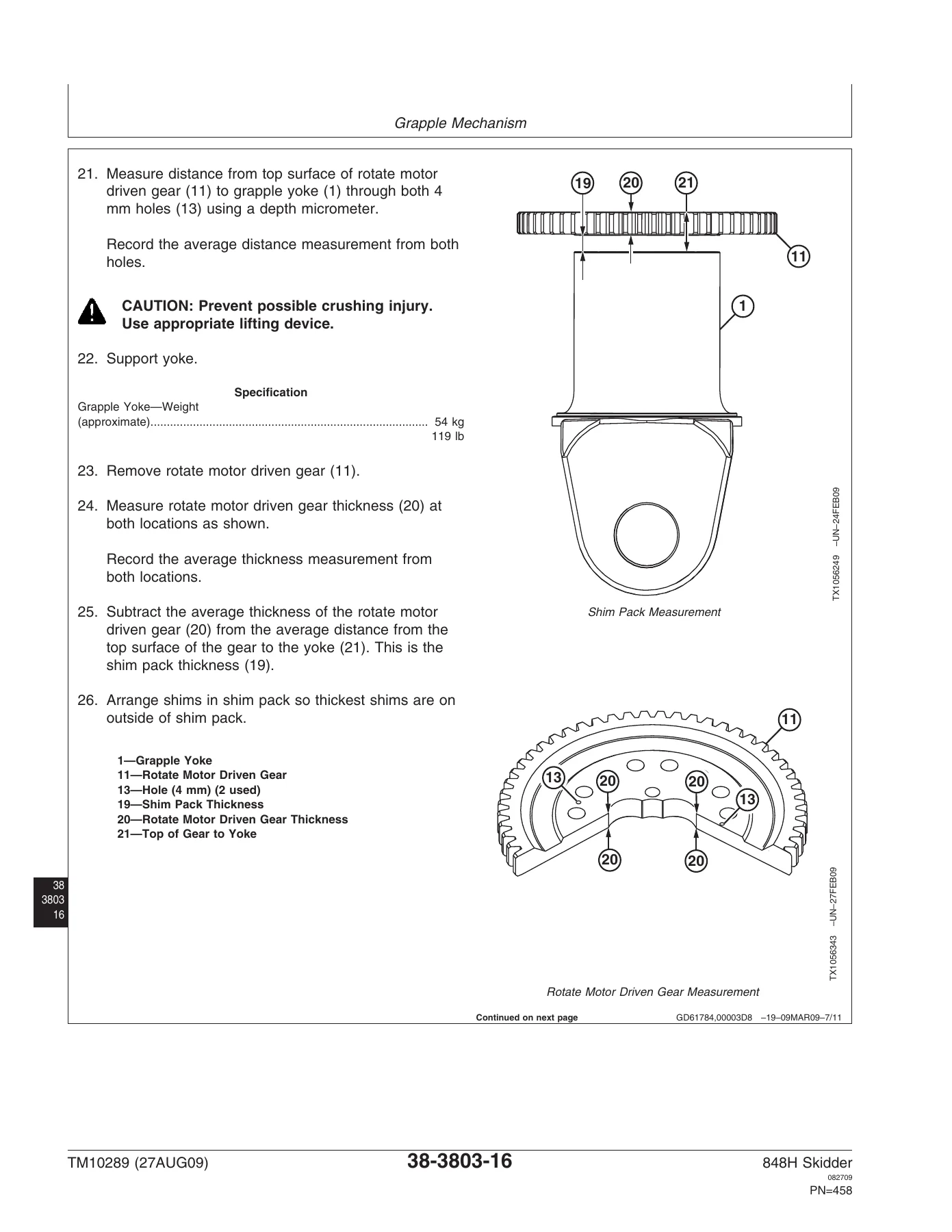
The transmission section is especially detailed for the 848H, covering removal, controls adjustment, winch drive gearing, power shift clutches, and the charge pump. Torque converter disassembly and reassembly are covered with component weight specifications and lifting tool callouts. The axle section handles both front and rear TeamMate IV 1200 and 1400 Series inboard planetary units, including oscillation support repair and differential lock solenoid service. Steering coverage spans the standard hydraulic steering valve, steering cylinder, secondary (emergency) steering pump, and dual mode steering solenoid valve. The main hydraulic system section addresses the primary pump and the 63 L (16.6 gal) reservoir. Winch coverage includes both 40/4000 and 60/6000 Series units with oil capacity data, drive shaft repair, clutch/drive service, and control cable adjustment. The grapple chapter is thorough — damper repair and adjustment, yoke bearing service with precise bearing heating temperatures and shim measurement procedures, rotary manifold, and all associated hydraulic valve work.
What This Manual Enables
With the John Deere 848H Skidder Repair Technical Manual TM10289, a technician can execute the full repair cycle on a 848H without guesswork. Transmission oil capacity (approximately 29 L / 30.7 qt), hydraulic reservoir capacity (approximately 63 L / 16.6 gal), axle fluid capacities, winch oil fills, component weights for safe lifting, and a complete set of torque specifications from rim-to-axle flange cap screws (860 N•m / 635 lb-ft) to frame cap screws (488–596 N•m / 360–440 lb-ft) are all drawn directly from the document. Correct procedures — not guesswork — keep a machine in service and keep warranty exposure low.
This is an instant PDF download. No shipping, no waiting — purchase, download, and begin work on any device. The file is printable if a shop copy is needed. Download the 848H Skidder Repair Technical Manual TM10289 now and put accurate John Deere service data in your hands today.


Reviews
There are no reviews yet.