Trusted Business
Verified & Licensed
Virus Free Files
100% Safe Downloads
Secure Payment
SSL Protected
Instant Delivery
Available Immediately
John Deere 850J Crawler Dozer Operation & Test Technical Manual TM1730 – PDF DOWNLOAD
$34.95
John Deere 850J Crawler Dozer Operation & Test Technical Manual TM1730 – PDF DOWNLOAD
Instant PDF Download
Available immediately
Save to Your Device
Download & keep forever
Antivirus Scanned
100% virus-free
Trusted Worldwide
175,000+ customers
Description
John Deere 850J Crawler Dozer Operation & Test Technical Manual TM1730 – PDF DOWNLOAD
FILE DETAILS:
John Deere 850J Crawler Dozer Operation & Test Technical Manual TM1730 – PDF DOWNLOAD
Language : English
Pages : 964
Downloadable : Yes
File Type : PDF
IMAGES PREVIEW OF THE MANUAL:
DESCRIPTION:
John Deere 850J Crawler Dozer Operation & Test Technical Manual TM1730 – PDF DOWNLOAD
- This manual is written for an experienced technician. Essential tools required in performing certain service work are identified in this manual and are recommended for use.
- Live with safety: Read the safety messages in the introduction of this manual and the cautions presented throughout the text of the manual.
- This is the safety-alert symbol. When you see this symbol on the machine or in this manual, be alert to the potential for personal injury.
- Technical manuals are divided in two parts: repair and operation and tests. Repair sections tell how to repair the components. Operation and tests sections help you identify the majority of routine problems quickly.
- Information is organized in groups for the various components requiring service instruction. At the beginning of each group are summary listings of all applicable essential tools, service equipment and tools, other materials needed to do the job, service parts kits, specifications, wear tolerances, and torque values.
- Technical Manuals are concise guides for specific machines. They are on-the-job guides containing only the vital information needed for diagnosis, analysis, testing, and repair.
TABLE OF CONTENTS:
John Deere 850J Crawler Dozer Operation & Test Technical Manual TM1730 – PDF DOWNLOAD
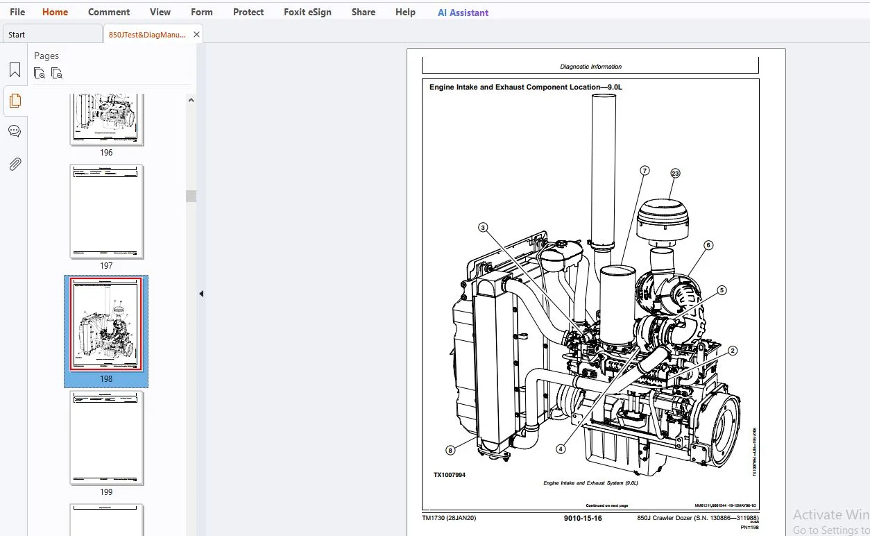
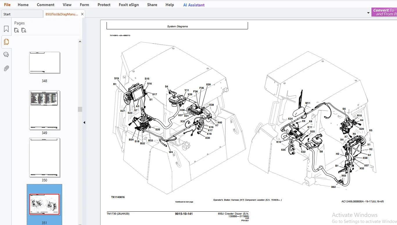
Contents...............................................................................................................  5
	General Information................................................................................................  7
		Safety.........................................................................................................  9
			Recognize Safety Information...............................................................................  9
			Follow Safety Instructions.................................................................................  9
			Operate Only If Qualified..................................................................................  9
			Wear Protective Equipment.................................................................................. 10
			Avoid Unauthorized Machine Modifications................................................................... 10
			Inspect Machine............................................................................................ 10
			Stay Clear of Moving Parts................................................................................. 10
			Avoid High-Pressure Fluids................................................................................. 11
			Beware of Exhaust Fumes.................................................................................... 11
			Prevent Fires.............................................................................................. 12
			Prevent Battery Explosions................................................................................. 12
			Handle Chemical Products Safely............................................................................ 12
			Dispose of Waste Properly.................................................................................. 13
			Prepare for Emergencies.................................................................................... 13
			Add Cab Guarding For Special Uses.......................................................................... 13
			Use Steps and Handholds Correctly.......................................................................... 14
			Start Only From Operator's Seat............................................................................ 14
			Use and Maintain Seat Belt................................................................................. 14
			Prevent Unintended Machine Movement........................................................................ 14
			Avoid Work Site Hazards.................................................................................... 15
			Keep Riders Off Machine.................................................................................... 15
			Avoid Backover Accidents................................................................................... 16
			Avoid Machine Tip Over and Machine Damage.................................................................. 16
			Add and Operate Attachments Safely......................................................................... 16
			Park and Prepare for Service Safely........................................................................ 17
			Service Cooling System Safely.............................................................................. 17
			Remove Paint Before Welding or Heating..................................................................... 17
			Make Welding Repairs Safely................................................................................ 18
			Drive Metal Pins Safely.................................................................................... 18
	Diagnostic Trouble Codes (DTC)..................................................................................... 23
		CAN Monitor Unit (CMU) Diagnostic Trouble Codes................................................................ 25
			Diagnostic Trouble Code (DTC) Quick Reference List—CAN Monitor Unit (CMU).................................. 25
			96.03 — Fuel Level Sensor Open or Short.................................................................... 25
			96.04 — Fuel Level Sensor Short to Ground.................................................................. 26
			107.03 — Engine Air Filter Restriction Indicator Switch Short to Power..................................... 26
			107.04 — Engine Air Filter Restricted...................................................................... 26
			177.03 — Transmission Oil Temperature Sensor Short to Power................................................ 27
			177.04 — Transmission Oil Temperature Sensor Short to Ground............................................... 27
			177.16 — Transmission Oil Temperature High................................................................. 27
				Transmission Oil Temperature High...................................................................... 27
			609.09 — CAN Communication Error, No TCU Message........................................................... 28
			1638.00 — Hydraulic Oil Temperature High................................................................... 28
			1638.03 — Hydraulic Oil Temperature Short to Power......................................................... 28
			1638.04 — Hydraulic Oil Temperature Short to Ground........................................................ 29
			1713.31 — Hydraulic Oil Filter Restricted.................................................................. 29
				Hydraulic Oil Filter Restricted Diagnostic Procedure................................................... 29
			2000.09 — CAN Communication Error, No ECU Configuration.................................................... 31
			3156.09 — CAN Blade Mode Missing From EHC.................................................................. 32
			3359.31 — Transmission Oil Filter Restricted............................................................... 32
				Transmission Oil Filter Restricted Diagnostic Procedure................................................ 32
			524227.31 — Fan Oil Filter Restricted...................................................................... 34
				Fan Oil Filter Restricted Diagnostic Procedure......................................................... 34
		Engine Control Unit (ECU) Diagnostic Trouble Codes............................................................. 37
			Diagnostic Trouble Code (DTC) Quick Reference List—Engine Control Unit (ECU)............................... 37
		Transmission Control Unit (TCU) Diagnostic Trouble Codes....................................................... 39
			Diagnostic Trouble Code (DTC) Quick Reference List—Transmission Control Unit (TCU)......................... 39
			70.00 — Park Lock Lever Inputs Both ON..................................................................... 41
			70.01 — Park Lock Lever Inputs Both OFF.................................................................... 42
			91.00 — Throttle Sensor Input Greater Than Maximum Calibration Value....................................... 43
			91.01 — Throttle Sensor Input Less Than Minimum Calibration Value.......................................... 44
			91.03 — Throttle Sensor Short to Power..................................................................... 45
			91.04 — Throttle Sensor Open or Short...................................................................... 46
			91.15 — Throttle Sensor Minimum Calibration Value Too High................................................. 46
			91.16 — Throttle Sensor Maximum Calibration Value Too High................................................. 47
			91.17 — Throttle Sensor Minimum Calibration Value Too Low.................................................. 47
			91.18 — Throttle Sensor Maximum Calibration Value Too Low.................................................. 48
			116.00 — Brake Pressure High............................................................................... 48
				Brake Pressure Low Diagnostic Procedure................................................................ 48
			116.01 — Brake Pressure Low................................................................................ 49
				Brake Pressure Low Diagnostic Procedure................................................................ 49
			116.03 — Brake Pressure Short to Power..................................................................... 51
			116.04 — Brake Pressure Open or Short...................................................................... 52
			158.03 — TCU System Volts Too High......................................................................... 52
			158.04 — TCU System Volts Too Low.......................................................................... 53
			177.00 — Transmission Over Temp............................................................................ 53
			190.09 — CAN Communication Error No Engine Speed........................................................... 53
			190.19 — CAN Communication Error Invalid Engine Speed...................................................... 54
			521.00 — Decel Sensor Input Greater Than Maximum Calibration Value......................................... 54
			521.01 — Decel Sensor Input Less Than Minimum Calibration Value............................................ 55
			521.03 — Decel Sensor Short to Power....................................................................... 56
			521.04 — Decel Sensor Open or Short........................................................................ 57
			521.05 — Decel Sensor Brake Calibration Value Too Low...................................................... 58
			521.06 — Decel Sensor Brake Calibration Value Too High..................................................... 58
			521.15 — Decel Sensor Minimum Calibration Value Too High................................................... 59
			521.16 — Decel Sensor Maximum Calibration Value Too Low.................................................... 59
			521.17 — Decel Sensor Minimum Calibration Value Too Low.................................................... 60
			521.18 — Decel Sensor Maximum Calibration Value Too Low.................................................... 60
			581.00 — Speed Buttons Input Greater Than Maximum Calibration Value........................................ 60
				Transmission Speed Control Sensor Input Greater Than Maximum Calibration Value Diagnostic Procedure.... 61
			581.01 — Speed Buttons Input Less Than Minimum Calibration Value........................................... 62
			581.03 — Speed Buttons Short to Power...................................................................... 63
			581.04 — Speed Buttons Open or Short....................................................................... 64
			581.15 — Speed Buttons Minimum Calibration Value Too High.................................................. 65
			581.16 — Speed Buttons Maximum Calibration Value Too High.................................................. 66
			581.17 — Speed Buttons Minimum Calibration Value Too Low................................................... 67
			581.18 — Speed Buttons Maximum Calibration Value Too Low................................................... 68
			604.03 — FNR Neutral Switch Open Circuit................................................................... 69
			604.04 — FNR Neutral Switch Short Circuit.................................................................. 70
			604.15 — FNR Neutral Switch Minimum Calibration Value Too High............................................. 71
			604.16 — FNR Neutral Switch Maximum Calibration Value Too High............................................. 71
			604.17 — FNR Neutral Switch Minimum Calibration Value Too Low.............................................. 72
			604.18 — FNR Neutral Switch Maximum Calibration Value Too Low.............................................. 72
			619.05 — Brake Solenoid No Response........................................................................ 73
			620.03 — TCU 5V Supply Short to Power...................................................................... 74
			620.04 — TCU 5V Supply Open or Short....................................................................... 76
			907.03 — Left Speed Sensor Short to Power.................................................................. 78
			907.04 — Left Speed Sensor Short........................................................................... 79
			907.07 — Left Speed Sensor No Response..................................................................... 80
			907.12 — Left Speed Sensor Open............................................................................ 80
			908.03 — Right Speed Sensor Short to Power................................................................. 81
			908.04 — Right Speed Sensor Short.......................................................................... 82
			908.07 — Right Speed Sensor No Response.................................................................... 83
			908.12 — Right Speed Sensor Open........................................................................... 83
			977.05 — Fan Reverse Solenoid No Response.................................................................. 84
			1071.05 — Fan Drive Solenoid Open Circuit.................................................................. 84
			1071.06 — Fan Drive Solenoid Short Circuit................................................................. 85
			2660.00 — Steer Sensor Input Greater Than Maximum Calibration Value........................................ 85
			2660.01 — Steer Sensor Input Less Than Minimum Calibration Value........................................... 86
			2660.03 — Steer Sensor Short to Power...................................................................... 87
			2660.04 — Steer Sensor Open or Short....................................................................... 88
			2660.15 — Steer Sensor Minimum Calibration Value Too High.................................................. 89
			2660.16 — Steer Sensor Maximum Calibration Value Too Low................................................... 89
			2660.17 — Steer Sensor Minimum Calibration Value Too Low................................................... 90
			2660.18 — Steer Sensor Maximum Calibration Value Too Low................................................... 90
			2661.00 — FNR Sensor Input Greater Than Maximum Calibration Value.......................................... 91
			2661.01 — FNR Sensor Input Less Than Minimum Calibration Value............................................. 91
			2661.03 — FNR Sensor Short to Power........................................................................ 92
			2661.04 — FNR Sensor Open or Short......................................................................... 93
			2661.15 — FNR Sensor Minimum Calibration Value Too High.................................................... 94
			2661.16 — FNR Sensor Maximum Calibration Value Too Low..................................................... 94
			2661.17 — FNR Sensor Minimum Calibration Value Too Low..................................................... 95
			2661.18 — FNR Sensor Maximum Calibration Value Too Low..................................................... 95
			522439.05 — Tank Bypass Solenoid Open Circuit.............................................................. 96
			522440.05 — Blade Left Solenoid Open Circuit............................................................... 96
			522440.06 — Blade Left Solenoid Short Circuit.............................................................. 97
			522441.05 — Blade Right Solenoid Open Circuit.............................................................. 97
			522441.06 — Blade Right Solenoid Short Circuit............................................................. 98
			522442.00 — Blade Buttons Input Greater Than Maximum Calibration Value..................................... 99
			522442.01 — Blade Buttons Input Less Than Minimum Calibration Value........................................100
			522442.03 — Blade Buttons Short to Power...................................................................101
			522442.04 — Blade Buttons Open or Short....................................................................102
			522442.15 — Blade Buttons Minimum Calibration Value Too High...............................................103
			522442.16 — Blade Buttons Maximum Calibration Value Too High...............................................104
			522442.17 — Blade Buttons Minimum Calibration Value Too Low................................................105
			522442.18 — Blade Buttons Maximum Calibration Value Too Low................................................106
			522444.00 — Charge Pressure High...........................................................................106
			522444.01 — Charge Pressure Low............................................................................107
			522444.03 — Charge Pressure Short to Power.................................................................107
			522444.04 — Charge Pressure Open or Short..................................................................108
			522447.05 — Right Forward Pump Coil Open...................................................................108
				Right Forward Pump Coil Open Diagnostic Procedure......................................................108
			522447.06 — Right Forward Pump Coil Short..................................................................110
				Right Forward Pump Coil Short Diagnostic Procedure.....................................................110
			522447.15 — Right Forward Pump Threshold Calibration Value Too High........................................112
				Right Forward Pump Threshold Calibration Value Too High Diagnostic Procedure...........................113
			522447.16 — Right Forward Pump Max Speed Calibration Value Too High........................................113
			522447.17 — Right Forward Pump Threshold Calibration Value Too Low.........................................113
				Right Forward Pump Threshold Calibration Value Too High Diagnostic Procedure...........................114
			522447.18 — Right Forward Pump Max Speed Calibration Value Too Low.........................................114
			522448.05 — Right Reverse Pump Coil Open...................................................................114
				Right Reverse Pump Coil Open Diagnostic Procedure......................................................115
			522448.06 — Right Reverse Pump Coil Short..................................................................116
				Right Reverse Pump Coil Short Diagnostic Procedure.....................................................117
			522448.15 — Right Reverse Pump Threshold Calibration Value Too High........................................118
				Right Reverse Pump Threshold Calibration Value Too High Diagnostic Procedure...........................119
			522448.16 — Right Reverse Pump Max Speed Calibration Value Too High........................................119
			522448.17 — Right Reverse Pump Thresh Calibration Value Too Low............................................119
				Right Reverse Pump Threshold Calibration Value Too High Diagnostic Procedure...........................120
			522448.18 — Right Reverse Pump Max Speed Calibration Value Too Low.........................................120
			522449.05 — Left Reverse Pump Coil Open....................................................................120
				Left Reverse Pump Coil Open Diagnostic Procedure.......................................................121
			522449.06 — Left Reverse Pump Coil Short...................................................................122
				Left Reverse Pump Coil Open Diagnostic Procedure.......................................................123
			522449.15 — Left Reverse Pump Threshold Calibration Value Too High.........................................124
				Left Reverse Pump Threshold Calibration Value Too High Diagnostic Procedure............................125
			522449.16 — Left Reverse Pump Max Speed Calibration Value Too Low..........................................125
			522449.17 — Left Reverse Pump Threshold Calibration Value Too Low..........................................125
				Left Reverse Pump Threshold Calibration Value Too High Diagnostic Procedure............................126
			522449.18 — Left Reverse Pump Max Speed Calibration Value Too Low..........................................126
			522450.05 — Left Forward Pump Coil Open....................................................................126
				Left Forward Pump Coil Open Diagnostic Procedure.......................................................127
			522450.06 — Left Forward Pump Coil Short...................................................................128
				Left Forward Pump Coil Short Diagnostic Procedure......................................................129
			522450.15 — Left Forward Pump Threshold Calibration Value Too High.........................................130
				Left Forward Pump Threshold Calibration Value Too High Diagnostic Procedure............................131
			522450.16 — Left Forward Pump Max Speed Calibration Value Too High.........................................131
			522450.17 — Left Forward Pump Threshold Calibration Value Too Low..........................................131
				Left Forward Pump Threshold Calibration Value Too High Diagnostic Procedure............................132
			522450.18 — Left Forward Pump Max Speed Calibration Value Too Low..........................................132
			522451.05 — Cooler Bypass Solenoid No Response.............................................................133
			523108.13 — TCU Not Calibrated High Speed Not Done.........................................................133
			523108.14 — TCU Not Calibrated Sensor/Pump/Motor...........................................................133
			523436.07 — TCU Watchdog Timer Exceeded....................................................................133
			523577.05 — Left Motor Solenoid Open Circuit...............................................................134
			523577.06 — Left Motor Solenoid Short Circuit..............................................................134
			523577.16 — Left Motor Maximum Calibration Value Too High..................................................134
			523577.18 — Left Motor Maximum Calibration Value Too Low...................................................135
			523578.05 — Right Motor Solenoid Open Circuit..............................................................135
			523578.06 — Right Motor Solenoid Short Circuit.............................................................135
			523578.16 — Right Motor Maximum Calibration Value Too High.................................................136
			523578.18 — Right Motor Maximum Calibration Value Too Low..................................................136
		Electro-Hydraulic Controller (EHC) Diagnostic Trouble Codes....................................................137
			Diagnostic Trouble Code (DTC) Quick Reference List—Electro-Hydraulic Controller (EHC)......................137
			158.03 — EHC System Volts Too High.........................................................................137
			158.04 — EHC System Volts Too Low..........................................................................138
			620.03 — Sensor Short to Power.............................................................................138
			620.04 — Sensor Short to GND...............................................................................138
			1903.00 — Aux 1 PVE Open Circuit...........................................................................139
			1903.01 — Aux 1 PVE Low or Open Circuit....................................................................139
			1903.03 — Aux 1 PVE Short to Power.........................................................................139
			1903.04 — Aux 1 PVE Short to GND...........................................................................139
			1903.31 — Aux 1 PVE Spool Pos Error........................................................................140
			1915.00 — Aux 2 PVE Open Circuit...........................................................................140
			1915.01 — Aux 2 PVE Low or Open Circuit....................................................................140
			1915.03 — Aux 2 PVE Short to Power.........................................................................141
			1915.04 — Aux 2 PVE Short to GND...........................................................................141
			1915.31 — Aux 2 PVE Spool Pos Error........................................................................141
			2660.09 — CAN Jstk Pos Missing From BCJ....................................................................141
			2712.00 — Hyd Enable Sw Inputs Both On.....................................................................142
			2712.01 — Hyd Enable Sw Inputs Both Off....................................................................142
			3157.03 — Incr / Decr Buttons Short to Power...............................................................142
			3157.04 — Incr / Decr Buttons Open or Short................................................................143
			3157.31 — Incr / Decr Buttons Invalid Output...............................................................143
			522442.03 — Blade Buttons Short to Power...................................................................143
			522442.04 — Blade Buttons Open or Short....................................................................144
			522422.31 — Blade Buttons Invalid Output...................................................................144
			523779.00 — Blade Rotate Current Above Max.................................................................144
			523779.01 — Blade Rotate Current Below Min.................................................................144
			523780.00 — Tilt PVE Open Circuit..........................................................................145
			523780.01 — Tilt PVE Low or Open Circuit...................................................................145
			523780.03 — Tilt PVE Short to Power........................................................................145
			523780.04 — Tilt PVE Short to GND..........................................................................145
			523780.31 — Tilt PVE Spool Pos Error.......................................................................146
			523781.00 — Height PVE Open Circuit........................................................................146
			523781.01 — Height PVE Low or Open Circuit.................................................................146
			523781.03 — Height PVE Short to Power......................................................................147
			523781.04 — Height PVE Short to GND........................................................................147
			523781.31 — Height PVE Spool Pos Error.....................................................................147
			524059.00 — Aux 2 Jstk Sensor 2 Volts High.................................................................148
			524059.01 — Aux 2 Jstk Sensor 2 Volts Low..................................................................148
			524059.03 — Aux 2 Jstk Sensor 2 Short to Power.............................................................148
			524059.04 — Aux 2 Jstk Sensor 2 Short to GND...............................................................148
			524059.31 — Aux 2 Jstk Sensor 2 Invalid Output.............................................................148
			524062.00 — Aux 1 Jstk Sensor 2 Volts High.................................................................148
				Sensor 2 of Auxiliary Joystick 1 Diagnostic Procedure..................................................148
			524062.01 — Aux 1 Jstk Sensor 2 Volts Low..................................................................150
				Sensor 2 of Auxiliary Joystick 1 Diagnostic Procedure..................................................150
			524062.03 — Aux 1 Jstk Sensor 2 Short to Power.............................................................152
			524062.04 — Aux 1 Jstk Sensor 2 Short to GND...............................................................152
			524062.31 — Aux 1 Jstk Sensor 2 Invalid Output.............................................................153
			524085.00 — Aux 2 Jstk Sensor 2 Volts High.................................................................153
			524085.01 — Aux 2 Jstk Sensor 2 Volts Low..................................................................153
			524085.03 — Aux 2 Jstk Sensor 1 Short to Power.............................................................153
			524085.04 — Aux 2 Jstk Sensor 1 Short to GND...............................................................153
			524085.14 — Aux 2 Jstk Sensor Mismatch.....................................................................153
			524085.31 — Aux 2 Jstk Sensor 1 Invalid Output.............................................................154
			524086.00 — Aux 1 Jstk Sensor 1 Volts High.................................................................154
				Sensor 1 of Auxiliary Joystick 1 Diagnostic Procedure..................................................154
			524086.01 — Aux 1 Jstk Sensor 1 Volts Low..................................................................155
				Sensor 1 of Auxiliary Joystick 1 Diagnostic Procedure..................................................155
			524086.03 — Aux 1 Jstk Sensor 1 Short to Power.............................................................157
			524086.04 — Aux 1 Jstk Sensor 1 Short to GND...............................................................157
			524086.14 — Aux 1 Jstk Sensor Mismatch.....................................................................158
			524086.31 — Aux 1 Jstk Sensor 1 Invalid Output.............................................................158
		Blade Control Joystick (BCJ) Diagnostic Trouble Codes..........................................................159
			Diagnostic Trouble Code (DTC) Quick Reference List—Blade Control Joystick (BCJ)............................159
			2697.03 — Voltage Too High (X Axis)........................................................................159
			2697.04 — Voltage Too Low (X Axis).........................................................................159
			2697.13 — Input Not Calibrated (X Axis)....................................................................159
			2697.14 — Redundant Input Failure (X Axis).................................................................159
			2698.03 — Voltage Too High (Y Axis)........................................................................160
			2698.04 — Voltage Too Low (Y Axis).........................................................................160
			2698.13 — Input Not Calibrated (Y Axis)....................................................................160
			2698.14 — Redundant Input Failure (Y Axis).................................................................160
	Operational Checkout Procedure.....................................................................................161
		Operational Checkout Procedure.................................................................................163
			Operational Checkout.......................................................................................163
				Diagnostic Trouble Code (DTC) Check....................................................................163
				Operational Checks—Key Switch OFF, Engine OFF..........................................................163
				Operational Checks—Key Switch ON, Engine OFF...........................................................164
				Operational Checks—Key Switch ON, Engine ON............................................................169
	Engine.............................................................................................................179
		Theory of Operation............................................................................................181
			POWERTECH 8.1L Diesel Engines..............................................................................181
			POWERTECH PLUS 9.0L Diesel Engines.........................................................................181
		Diagnostic Information.........................................................................................183
			Engine Identification......................................................................................183
			Diagnose Engine Malfunctions—8.1L..........................................................................185
			Diagnose Engine Malfunctions—9.0L..........................................................................186
			Engine Cooling System Component Location—8.1L..............................................................190
			Engine Cooling System Component Location—9.0L..............................................................192
			Engine Fuel System Component Location—8.1L.................................................................193
			Engine Fuel System Component Location—9.0L.................................................................195
			Engine Intake and Exhaust Component Location—8.1L..........................................................196
			Engine Intake and Exhaust Component Location—9.0L..........................................................198
		Tests..........................................................................................................201
			POWERTECH 8.1L Diesel Engines..............................................................................201
			POWERTECH PLUS 9.0L Diesel Engines.........................................................................201
			Intake Manifold Pressure Test—Turbocharger Boost (8.1L Only)...............................................201
			Fuel Supply Pump Pressure Test.............................................................................202
	Electrical System..................................................................................................204
		System Information.............................................................................................205
			Electrical Diagram Information.............................................................................205
		System Diagrams................................................................................................211
			Fuse and Relay Specifications..............................................................................211
			System Functional Schematic, Wiring Diagram, and Component Location Legend—9.0L............................217
			System Functional Schematic and Section Legend—9.0L........................................................222
			System Functional Schematic, Wiring Diagram, and Component Location Legend—8.1L............................278
			System Functional Schematic and Section Legend—8.1L........................................................282
			JDLink™ System Functional Schematic—MIG/GTT................................................................337
			JDLink™ System Functional Schematic—MTG/SAT................................................................341
			Operator's Station Harness (W7) Component Location.........................................................345
			Operator's Station Harness (W7) Wiring Diagram.............................................................355
			Canopy Roof Harness (W8) Component Location................................................................388
			Canopy Roof Harness (W8) Wiring Diagram....................................................................391
			Cab Roof Harness (W9) Component Location...................................................................394
			Cab Roof Harness (W9) Wiring Diagram.......................................................................399
			Engine Harness (W10) Component Location....................................................................417
			Engine Harness (W10) Wiring Diagram........................................................................428
			Transmission Harness (W11) Component Location..............................................................443
			Transmission Harness (W11) Wiring Diagram..................................................................458
			Air Conditioning Harness (W14) Component Location..........................................................482
			Air Conditioning Harness (W14) Wiring Diagram..............................................................485
			Radio Harness (W15) Component Location.....................................................................488
			Radio Harness (W15) Wiring Diagram.........................................................................490
			IGC Machine Harness (W21) and IGC Cab Harness (W22) Component Location.....................................493
			Integrated Grade Control (IGC) Machine Harness (W21) Wiring Diagram........................................497
			Integrated Grade Control (IGC) Cab Harness (W22) Wiring Diagram............................................507
			Pressure Sensor Harness (W27) Wiring Diagram...............................................................510
			JDLink™ System Harnesses Component Location—MIG/GTT........................................................510
			JDLink™ System Harnesses Component Location—MTG/SAT........................................................514
			JDLink™ System Wiring Diagrams—MIG/GTT.....................................................................516
			JDLink™ System Wiring Diagrams—MTG/SAT.....................................................................524
		Sub-System Diagnostics.........................................................................................529
			Starting and Charging Circuit Theory of Operation..........................................................529
			Controller Area Network (CAN) Theory of Operation..........................................................537
			Engine Control Unit (ECU) Circuit Theory of Operation—9.0L.................................................541
			Engine Control Unit (ECU) Circuit Theory of Operation—8.1L.................................................553
			Transmission Control Unit (TCU) Circuit Theory of Operation................................................557
			CAN Monitor Unit (CMU) Circuit Theory of Operation.........................................................573
			Integrated Grade Control (IGC) Theory of Operation—If Equipped.............................................577
			JDLink™ Circuit Theory of Operation—If Equipped............................................................583
		References.....................................................................................................587
			Electrical Component Specifications........................................................................587
			Service ADVISOR™ Diagnostic Application....................................................................593
			Service ADVISOR™ Connection Procedure......................................................................593
			Reading Diagnostic Trouble Codes with Service ADVISOR™ Diagnostic Application..............................594
			JDLink™ System Identification..............................................................................596
			JDLink™ Connection Procedure—If Equipped...................................................................599
			CAN Monitor Unit (CMU) Menu Structure—Service Mode.........................................................600
			Integrated Grade Control (IGC) Checks—If Equipped..........................................................604
				IGC System Checks......................................................................................604
			Integrated Grade Control (IGC) Diagnose Malfunctions—If Equipped...........................................609
				All Blade Functions Do Not Operate in Manual or Auto Modes.............................................609
				All Blade Functions Operate Normally in Manual Mode, But Not in Auto Mode..............................614
				All Blade Functions Operate Normally in Auto Mode, But Not in Manual Mode..............................617
				Blade Lift and Tilt Operate Normally in Auto Mode, But Not in Manual Mode..............................619
				Blade Lift and Tilt Operate Normally, But Blade Angle Does Not.........................................621
				Blade Lift and Angle Operate Normally, But Blade Incr/Decr Does Not....................................624
				Blade Response Is Not Smooth...........................................................................625
				All Blade Functions Are Slow or Sluggish...............................................................627
				Blade Response Is Too Fast.............................................................................628
				Blade Moves Quickly (Jumps) to One Side, Then Slowly Comes Back on Grade...............................629
				Waves in Graded Surface................................................................................630
			Alternator Test Procedure..................................................................................631
			CAN Circuit Test...........................................................................................632
				Controller Area Network (CAN) Diagnostics .............................................................632
			Transmission Control Unit (TCU) Calibration................................................................637
			Wire Harness Test..........................................................................................638
			Decelerator/Brake Pedal Adjustment.........................................................................638
			Engine Speed Control Remove and Install....................................................................639
			Rotary Sensor Remove and Install...........................................................................640
			Transmission Control Lever (TCL) Adjustment................................................................641
			Bussed Sensor Connectors (X6 and X7) Diagnostics...........................................................643
			Engine Control Unit (ECU) Remove and Install...............................................................645
			Replace Weather Pack™ Connector............................................................................646
			Install Weather Pack™ Contact..............................................................................647
			Replace DEUTSCH® Connectors................................................................................648
			Replace DEUTSCH® Rectangular or Triangular Connectors......................................................649
			Install DEUTSCH® Contact...................................................................................650
			Replace CINCH® Connectors..................................................................................651
			Install CINCH® Contact.....................................................................................653
			Repair 32 and 48 Way CINCH® Connectors.....................................................................654
			Replace (Pull Type) Metri-Pack™ Connectors.................................................................657
			Replace (Push Type) Metri-Pack™ Connectors.................................................................658
	Hydraulics.........................................................................................................659
		Theory.........................................................................................................661
			Hydraulic System Operation.................................................................................661
			Hydraulic Pump Operation...................................................................................662
			Pressure Reducing Valve Operation..........................................................................671
			Pilot Control Valve Operation..............................................................................673
			Hydraulic Control Valve Operation..........................................................................675
			Hydraulic Control Valve Operation—IGC......................................................................677
			Load Sense Circuit Operation...............................................................................683
			Load Sense Isolator Operation..............................................................................683
			Circuit Relief Valve with Anticavitation Operation.........................................................684
			Hydraulic System Relief Valve Operation....................................................................685
			Hydraulic Oil Filter Manifold Operation....................................................................686
			Blade Angle Operation......................................................................................689
			Ripper Operation...........................................................................................693
			Ripper Operation with IGC Controlled Auxiliary Valve.......................................................699
			Hydraulic Cylinder Operation...............................................................................703
			Quick-Drop Valve Operation.................................................................................705
			Mechanical Angle Blade Operation...........................................................................708
		Diagnostic Information.........................................................................................711
			Hydraulic System Schematic.................................................................................711
			Hydraulic System Schematic—IGC.............................................................................755
			Hydraulic System Schematic—IGC with Auxiliary Valve........................................................759
			Main Hydraulic Component Location..........................................................................763
			Ripper Ready Hydraulic Component Location..................................................................767
			Winch Ready Hydraulic Component Location...................................................................771
			Main Hydraulic Component Location—IGC......................................................................775
			Hydraulic System Diagnose Malfunctions.....................................................................777
				No Hydraulic Functions Diagnostic Procedure............................................................777
				Hydraulic Functions Slow Diagnostic Procedure..........................................................778
				Hydraulic Pump Noisy Diagnostic Procedure..............................................................780
				Blade Float Does Not Work Diagnostic Procedure.........................................................781
				One Hydraulic Function Does Not Work Diagnostic Procedure..............................................781
				Function Drifts Down Diagnostic Procedure..............................................................782
				Oil Overheats Diagnostic Procedure.....................................................................783
			Hydraulic System Diagnose Malfunctions—IGC.................................................................784
				No Hydraulic Functions Diagnostic Procedure—IGC........................................................784
				Hydraulic Functions Slow Diagnostic Procedure—IGC......................................................785
				Blade Float Does Not Work Diagnostic Procedure—IGC.....................................................787
				One Hydraulic Function Does Not Work Diagnostic Procedure—IGC..........................................788
				Hydraulic Power Low Diagnostic Procedure—IGC...........................................................789
				Function Drifts Down Diagnostic Procedure—IGC..........................................................790
				Oil Overheats Diagnostic Procedure—IGC.................................................................791
				Blade Response Not Smooth Diagnostic Procedure—IGC.....................................................792
		Tests..........................................................................................................795
			JT02156A Digital Pressure/Temperature Analyzer Installation................................................795
			Ultra Clean® Hand Launcher.................................................................................795
			Hydraulic Oil Cleanup Procedure............................................................................795
			Hydraulic System Relief Valve Test.........................................................................796
			Hydraulic System Relief Valve Test—IGC.....................................................................797
			Circuit Relief Valve Test..................................................................................799
			Circuit Relief Valve Test—IGC..............................................................................800
			Pump Load Sense Differential and System Pressure (Pump Cutoff) Test and Adjustment.........................801
			Pump Load Sense Differential and System Pressure Test and Adjustment—IGC...................................804
			Lift and Tilt Cylinder Function Drift Test.................................................................806
			Hydraulic Cylinder Drift Test..............................................................................807
			Cylinder Leakage Test......................................................................................808
			Pressure Reducing Valve Pressure Test and Adjustment.......................................................809
			Blade Down Accumulator Hydraulic Discharge.................................................................809
			Blade Down Accumulator Precharge Test......................................................................810
			Hydraulic Pump Flow Test...................................................................................811
			Hydraulic Pump Case Drain Test.............................................................................812
	Hydrostatic System.................................................................................................814
		Theory of Operation............................................................................................815
			Hydrostatic System.........................................................................................815
			Transmission Control Circuit Operation (Flow Chart)........................................................816
			Charge Pump Operation......................................................................................817
			Hydrostatic Charge Oil Filter Operation....................................................................818
			Neutral Charge Relief Valve Operation......................................................................819
			Multi-Function Valve Operation.............................................................................820
			Hydraulic Integrated Circuit (HIC) Valve Operation.........................................................822
			Park Brake Valve Operation.................................................................................823
			Oil Cooler and Reservoir Bypass Operation..................................................................824
			Pump Pressure Control Pilot (PCP) Operation................................................................825
			Pump Displacement Control Valve (PDCV) Operation...........................................................826
			Hydrostatic Pump Operation.................................................................................827
			Flushing Valve and Operating Charge Relief Valve Operation.................................................828
			Hydrostatic Motor Operation................................................................................829
			Hydraulic Reversing Fan Drive Operation....................................................................831
			Hydraulic Non-Reversing Fan Drive Operation................................................................835
			Hydraulic Fan Return Filter Operation......................................................................837
		Diagnostic Information.........................................................................................839
			Overheating—Flowchart......................................................................................839
			Low Charge Pressure—Flowchart..............................................................................840
			Mistrack/Indexes—Flowchart.................................................................................841
			Machine Will Not Reach Full Speed—Flowchart................................................................842
			Low Power—Flowchart........................................................................................843
			Engine Starts But One Or Both Tracks Will Not Move—Flowchart...............................................845
			TCU Calibration Malfunctions...............................................................................846
				TCU Calibration Malfunctions Diagnostic Procedure......................................................846
			Hydrostatic System Component Location......................................................................855
			Park Brake System Component Location.......................................................................858
			Hydrostatic System Schematic—Neutral (Park Brake On).......................................................861
			Hydrostatic System Diagram—Neutral (Park Brake On).........................................................873
			Hydrostatic System Diagram—Reverse (Slow Speed)............................................................877
			Hydrostatic System Diagram—Forward (Fast Speed)............................................................881
		Tests..........................................................................................................885
			JT02156A Digital Pressure/Temperature Analyzer Installation................................................885
			Ultra Clean® Hand Launcher.................................................................................885
			Machine Supporting Procedure...............................................................................886
			Transmission Oil Warm-Up Procedure.........................................................................887
			Releasing Park Brake to Tow the Machine....................................................................889
			Hydrostatic Pump and Motor Initial Start-Up Procedure......................................................891
			Hydrostatic Pump Flushing Procedure........................................................................892
			Hydraulic Oil Cleanup Procedure............................................................................893
			Pressure Control Pilot (PCP) Manual Override Test..........................................................893
			Pressure Control Pilot (PCP) Test..........................................................................895
			Pressure Control Pilot (PCP) Internal Adjustment...........................................................897
			Multi-Function Relief Valve Test...........................................................................899
			Transmission Efficiency Test...............................................................................902
			Neutral Charge Relief and Operating Charge Relief Pressure Test............................................905
			Pump Displacement Control Valve (PDCV) Neutral (Null) Adjustment...........................................907
			Pump Servo Pressure Test...................................................................................910
			Motor Displacement Control Valve (MDCV) Adjustment.........................................................912
			Hydrostatic Motor Min./Max. Angle Servo Piston Pressure Test...............................................915
			Charge Pump Flow Test......................................................................................917
			Charge Pressure Sensor Test (S.N. 133015—).................................................................918
			Hydrostatic Oil Cooler Bypass Test.........................................................................920
			Hydrostatic Oil Reservoir Bypass Test......................................................................922
			Park Brake Test............................................................................................924
			Park Brake Relief Valve Test...............................................................................928
			Cab Tilt Relief Valve Test.................................................................................928
			Hand Pump Bleed Procedure..................................................................................929
			Fan Pump Pressure Test.....................................................................................930
			Fan Pump Flow Test.........................................................................................931
			Fan Motor Speed Test.......................................................................................933
			Fan Motor Case Drain Test..................................................................................934
	Heating and Air Conditioning.......................................................................................935
		Theory of Operation............................................................................................937
			Air Conditioning System Cycle Of Operation.................................................................937
		Diagnostic Information.........................................................................................939
			Diagnose Air Conditioning System Malfunctions..............................................................939
			Diagnose Heater System Malfunctions........................................................................942
		Tests..........................................................................................................945
			Proper Refrigerant Handling................................................................................945
			R134a Refrigerant Cautions.................................................................................945
			R134a Oil Charge Capacity..................................................................................945
			R134a Refrigerant Charge Capacity..........................................................................945
			Refrigerant Hoses And Tubing Inspection....................................................................946
			R134a Air Conditioning System Test.........................................................................947
			Operating Pressure Diagnostic Chart........................................................................949
			Air Conditioner Low Pressure Switch Test...................................................................951
			Air Conditioner High Pressure Switch Test..................................................................952
			Freeze Control Switch Test.................................................................................953
			Leak Testing...............................................................................................953
Page Number............................................................................................................  5
	Section 9000.......................................................................................................  7
		Group 01.......................................................................................................  9
	Section 9001....................................................................................................... 23
		Group 10....................................................................................................... 25
		Group 20....................................................................................................... 37
		Group 30....................................................................................................... 39
		Group 40.......................................................................................................137
		Group 50.......................................................................................................159
	Section 9005.......................................................................................................161
		Group 10.......................................................................................................163
	Section 9010.......................................................................................................179
		Group 05.......................................................................................................181
		Group 15.......................................................................................................183
		Group 25.......................................................................................................201
	Section 9015.......................................................................................................204
		Group 05.......................................................................................................205
		Group 10.......................................................................................................211
		Group 15.......................................................................................................529
		Group 20.......................................................................................................587
	Section 9025.......................................................................................................659
		Group 05.......................................................................................................661
		Group 15.......................................................................................................711
		Group 25.......................................................................................................795
	Section 9026.......................................................................................................814
		Group 05.......................................................................................................815
		Group 15.......................................................................................................839
		Group 25.......................................................................................................885
	Section 9031.......................................................................................................935
		Group 05.......................................................................................................937
		Group 15.......................................................................................................939
		Group 25.......................................................................................................945
S.S 23/02/2025