John Deere 892E LC Excavator Repair TECHNICAL MANUAL TM1542 – PDF DOWNLOAD
$30.95
John Deere 892E LC Excavator Repair TECHNICAL MANUAL TM1542 – PDF DOWNLOAD
Description
John Deere 892E LC Excavator Repair TECHNICAL MANUAL TM1542 – PDF DOWNLOAD
FILE DETAILS:
John Deere 892E LC Excavator Repair TECHNICAL MANUAL TM1542 – PDF DOWNLOAD
Language : English
Pages :574
Downloadable : Yes
File Type : PDF
IMAGES PREVIEW OF THE MANUAL:
DESCRIPTION:
John Deere 892E LC Excavator Repair TECHNICAL MANUAL TM1542 – PDF DOWNLOAD
Foreword
- This manual is written for an experienced technician. Essential tools required in performing certain service work are identified in this manual and are recommended for use. Live with safety: Read the safety messages in the introduction of this manual and the cautions presented throughout the text of the manual.
- This is the safety-alert symbol. When you see this symbol on the machine or in this manual, be alert to the potential for personal injury. Technical manuals are divided in two parts: repair and operation and tests. Repair sections tell how to repair the components.
- Operation and tests sections help you identify the majority of routine failures quickly. Information is organized in groups for the various components requiring service instruction. At the beginning of each group are summary listings of all applicable essential tools, service equipment and tools, other materials needed to do the job, service parts kits, specifications, wear tolerances, and torque values.
- Technical Manuals are concise guides for specific machines. They are on-the-job guides containing only the vital information needed for diagnosis, analysis, testing, and repair. Fundamental service information is available from other sources covering basic theory of operation, fundamentals of troubleshooting, general maintenance, and basic type of failures and their causes.
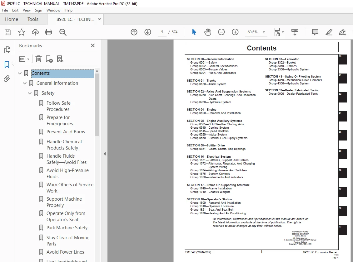
TABLE OF CONTENTS:
John Deere 892E LC Excavator Repair TECHNICAL MANUAL TM1542 – PDF DOWNLOAD
Contents 5
General Information 9
Safety 11
Follow Safe Procedures 11
Prepare for Emergencies 11
Prevent Acid Burns 12
Handle Chemical Products Safely 13
Handle Fluids Safely—Avoid Fires 13
Avoid High-Pressure Fluids 14
Warn Others of Service Work 14
Support Machine Properly 15
Operate Only from Operator’s Seat 15
Park Machine Safely 15
Stay Clear of Moving Parts 16
Avoid Power Lines 16
Use Handholds and Steps 16
Keep Riders Off Machine 17
Move and Operate Machine Safely 17
Wear Protective Clothing 17
Protect Against Flying Debris 18
Protect Against Noise 18
Illuminate Work Area Safely 18
Service Machines Safely 18
Remove Paint Before Welding or Heating 19
Avoid Heating Near Pressurized Fluid Lines 19
Beware of Exhaust Fumes 19
Use Proper Lifting Equipment 20
Service Cooling System Safely 20
Dispose of Waste Properly 20
Work in a Clean Area 21
Use Tools Properly 21
Replace Safety Signs 21
Live With Safety 22
General Specifications 23
892E LC 23
892E LC Drain And Refill Capacities 24
Torque Values 25
Unified Inch Bolt and Cap Screw Torque Values 25
Metric Bolt and Cap Screw Torque Values 26
Additional Metric Cap Screw Torque Values 27
Service Recommendations for O-Ring Boss Fittings 28
Service Recommendations for Flat Face O-Ring Seal Fittings 30
Service Recommendations for 37° Flare and 30° Cone Seat Connectors 31
Service Recommendations For Flared Connections—Straight or Tapered Threads 32
Service Recommendations For Inch Series Four Bolt Flange Fittings 33
Service Recommendations for Metric Series Four Bolt Flange Fitting 34
Fuels And Lubricants 35
Fuel Specifications 35
Low Sulfur Diesel Fuel Conditioner 35
Engine Oil 36
Hydraulic Oil 37
Swing Gearbox, Propel Gearbox And Pump Gearbox Oils 38
Track Roller, Front Idler, And Carrier Roller Oil 38
Grease 39
Engine Coolant 40
Lubricant Storage 40
Tracks 41
Track System 43
Service Equipment And Tools 43
Other Material 46
Specifications 47
Measure Track Chain And Roller Wear 49
Remove And Install Track Roller 50
Disassemble And Assemble Track Roller 52
Test Track Roller For Oil Leakage 55
Remove And Install Track Carrier Roller 55
Disassemble And Assemble Track Carrier Roller 57
Inspect Metal Face Seals 60
Remove And Install Track Shoe 61
Remove Track Chain 62
Install Track Chain 63
Disassemble And Assemble Track Chain 65
Disassemble And Assemble Track Chain To Replace Broken Part 66
Adjust Track Sag 67
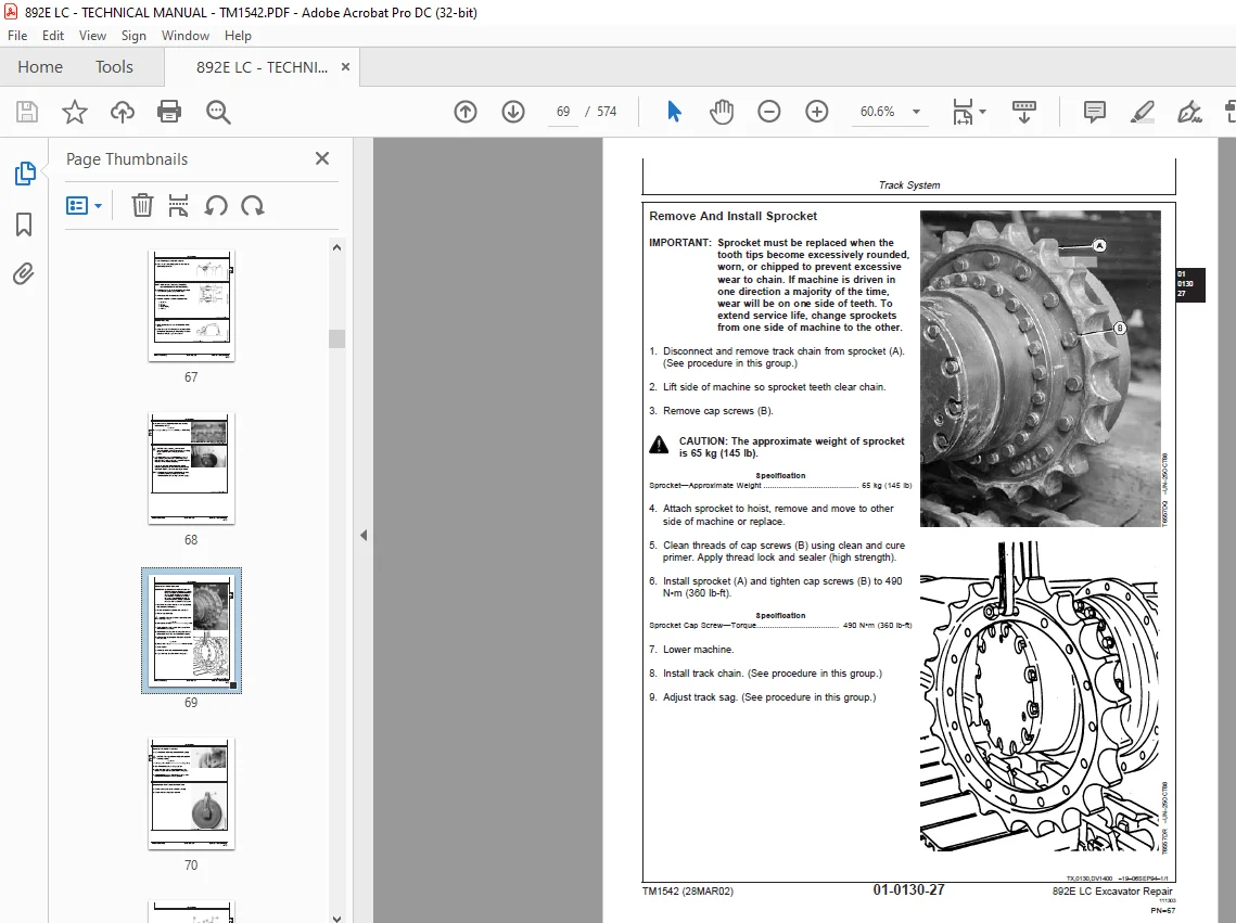
Remove And Install Sprocket 69
Remove And Install Front Idler 70
Disassemble And Assemble Front Idler 70
Test Front Idler For Oil Leakage 73
Remove And Install Track Adjuster Cylinder And Recoil Spring 73
Disassemble And Assemble Track Adjuster Recoil Spring 75
Disassemble And Assemble Track Adjuster Cylinder 79
Axles And Suspension Systems 81
Axle Shaft, Bearings, And Reduction Gears 83
Service Equipment And Tools 83
Other Material 84
Specifications 85
Towing Machine 85
Remove And Install Propel Gearbox 86
Disassemble Propel Gearbox 90
Inspect Metal Face Seals 96
Disassemble And Assemble First Planet Carrier 98
Disassemble And Assemble Second Planet Carrier 99
Disassemble And Assemble Third Planet Carrier 99
Assemble Propel Gearbox100
Hydraulic System109
Special Or Essential Tools109
Service Equipment And Tools109
Other Material111
Specifications112
Remove And Install Propel Motor And Brake (SN —010999)115
Disassemble Propel Motor And Brake (SN —010999)117
Assemble Propel Motor And Brake (SN —010999)124
Disassemble And Assemble Propel Motor Brake Valve Housing (SN —010999)129
Remove And Install Propel Motor And Brake (SN 011000—)133
Disassemble Propel Motor And Brake (SN 011000—)136
Assemble Propel Motor And Brake (SN 011000—)142
Disassemble And Assemble Propel Motor Brake Valve Housing (SN 011000— )150
Propel Motor Start-Up Procedure154
Remove And Install Rotary Manifold154
Disassemble And Assemble Rotary Manifold157
Rotary Manifold Air Test159
Engine161
Removal And Installation163
6076 John Deere Engine—Use CTM42163
Starting Motor—Use CTM77163
Special Or Essential Tools163
Service Equipment And Tools164
Specifications165
Remove And Install Engine165
Remove And Install Oil Pan173
Bleed Fuel System173
Measure And Adjust Engine Valve Clearances174
Remove And Install Starter175
Engine Auxiliary Systems177
Cold Weather Starting Aids179
Other Material179
Specifications179
Remove And Install Starting Aid Solenoid And Nozzle180
Remove And Install Engine Coolant Heater180
Cooling System183
Specifications183
Remove And Install Air Inlet Screen183
Remove And Install Fan, Shroud, And Guards184
Remove And Install Radiator185
Fill And Deaerate Cooling System187
Remove And Install Fan Belts189
Fan Belt Tension Adjustment190
Speed Controls191
Other Material191
Specifications191
Remove And Install Engine Speed Control Linkage192
Engine Speed Control Linkage Adjustment193
Remove And Install Engine Control (EC) Motor And Sensor195
Disassemble And Assemble Engine Control (EC) Motor And Sensor196
Intake System199
Special Or Essential Tools199
Service Equipment And Tools199
Specifications199
Remove And Install Air Cleaner200
Air Intake System Leakage Test201
External Fuel Supply Systems203
Other Material203
Specifications203
Remove And Install Fuel Tank204
Splitter Drive207
Gears, Shafts, And Bearings209
Other Material209
Specifications210
Remove And Install Splitter Housing210
Disassemble Splitter Housing215
Assemble Splitter Housing218
Remove And Install Dampener Drive (Flex Coupling)221
Electrical System223
Batteries, Support, And Cables225
Service Equipment And Tools225
Specifications225
Handle Batteries Safely226
Procedure For Testing Batteries227
Checking Electrolyte Specific Gravity228
Check Battery Electrolyte Level And Terminals230
Using Booster Batteries—24-Volt System231
Charge Battery233
Remove And Install Batteries236
Modification For Replacement Batteries238
Adding 12-Volt Accessories240
Alternator, Regulator, And Charging System Wiring241
Alternator Repair—Use CTM77241
Specifications241
Remove And Install Alternator242
Alternator Belt Tension Adjustment244
Wiring Harness And Switches245
Special Or Essential Tools245
Front Cab Electrical Component Identification (SN —010999)246
Rear Cab Electrical Component Identification (SN —010999)248
Front Chassis Electrical Component Identification (SN —010999)250
Hydraulic Electrical Component Identification (SN —010999)252
Engine Electrical Component Identification (SN —010999)254
Front Cab Electrical Component Identification (SN 011000—)256
Rear Cab Electrical Component Identification (SN 011000—)258
Front Chassis Electrical Component Identification (SN 011000— )260
Hydraulic Electrical Component Identification (SN 011000—)262
Engine Electrical Component Identification (SN 011000—)264
Connect Engine And Pump Controller (EPC) Harness Connector (SN —010999), Engine Controller (EC) And Pump And Valve Controller Harness Connector (SN 011000—)265
Disconnect Tab Retainer Connectors266
Replacing Fuses266
Fuse (Blade-Type) Color Codes267
Fuse Specifications267
Remove And Install Ground Strap268
Remove And Install Starter Switch268
Remove And Install Dome Light Switch270
Remove And Install Propel Alarm Cancel Switch And Start Aid Switch271
Replace DEUTSCH™ Connectors272
Install DEUTSCH™ Contact273
Replace WEATHER PACK™Connector274
Install WEATHER PACK™Contact275
Remove Connector Body From Blade Terminals276
System Controls277
Welding On Machine277
Connect Engine And Pump Controller (EPC) Harness Connector (SN —010999), Engine Controller (EC) And Pump And Valve Controller Harness Connector (SN 011000—)278
Remove And Install Engine And Pump Controller (EPC) (SN —010999)279
Remove And Install Engine Controller (EC), And Pump And Valve Controller (PCV) (SN 011000—)281
Remove And Install Monitor Controller282
Instruments And Indicators283
Replace Monitor Panel Bulbs283
Remove And Install Monitor Panel And Switch Panel 1283
Remove And Install Hour Meter, Coolant Temperature And Fuel Level Gauges286
Replace Switch Panel 2 Bulb287
Remove And Install Switch Panel 2288
Remove And Install Travel Alarm289
Changing Travel Alarm Volume290
Frame Or Supporting Structure291
Frame Installation293
Specifications293
Welding On Machine294
Welding Repair Of Major Structure296
Chassis Weights299
Service Equipment And Tools299
Specifications299
Remove And Install Counterweight300
Operator’s Station301
Removal And Installation303
Specifications303
Remove And Install Cab303
Operator Enclosure307
Remove And Window Pane And Two Piece Molding307
Remove And Install Windowpane And One Piece Molding308
Remove And Install Sliding Windows309
Windowpane Dimensions310
Seat And Seat Belt313
Specifications313
Remove And Install Seat313
Disassemble And Assemble Seat (SN —010999)314
Disassemble And Assemble Seat (SN 011000—)315
Disassemble And Assemble Seat Stand (SN —010999)316
Disassemble And Assemble Seat Stand (SN 011000—)318
Heating And Air Conditioning321
Remove And Install Heater Core321
Remove And Install Blower Motor322
Excavator323
Bucket325
Other Material325
Specifications325
Replacing Bucket Teeth326
Replacing Bucket Tooth Tip—Heavy-Duty Bucket327
Welding On Machine328
Remove And Install Tooth Shank329
Remove And Install Bucket And Linkage332
Adjust Bucket Linkage334
Replace Welded Bucket Cutting Edges335
Repair Cracked Cutting Edge335
Frames337
Other Material337
Specifications338
Remove And Install Arm339
Remove And Install Boom343
Inspect Arm And Boom Pins And Bushings347
Remove And Install Bushings And Seals348
Hydraulic System349
Service Equipment And Tools349
Other Material351
Specifications352
Engine And Pump Controller (EPC) Bypass Procedure (SN —010999)359
Electronic Control (EC) Bypass Procedure (SN 011000—)360
Control Lever Pattern Conversion (SN —010999)362
Control Lever Pattern Conversion (SN 011000—)363
Lower Boom With Engine Stopped364
Hydraulic Oil Cleanup Procedure Using Portable Filter Caddy366
Remove And Install Main Hydraulic Pump (SN —010999)367
Remove And Install Main Hydraulic Pump (SN 011000—)369
Hydraulic Pump Start-Up Procedure372
Disassemble Main Hydraulic Pump373
Assemble Main Hydraulic Pump382
Remove And Install Main Hydraulic Pump Regulator (SN —010999)389
Remove And Install Main Hydraulic Pump Regulator (SN 011000— )390
Disassemble And Assemble Main Hydraulic Pump Regulator393
Remove And Install Pilot Pump399
Disassemble And Assemble Pilot Pump401
Remove And Install Pilot Filter402
Hydraulic Oil Filter Inspection Procedure403
Remove And Install Pilot Control Manifold (SN —010999)403
Disassemble And Assemble Pilot Control Manifold (SN —010999)405
Remove And Install Pilot Pressure Regulating And Solenoid Valve Manifold (SN 011000—)409
Disassemble And Assemble Pilot Pressure Regulating And Solenoid Valve Manifold (SN 011000—)411
Remove And Install Pump Maximum Displacement Solenoid Valve (SN 011000— )415
Disassemble And Assemble Pump Maximum Displacement Solenoid Valve (SN 011000—)416
Remove And Install Grading And Precision Mode Shuttle Valve (SN 011000— )417
Remove And Install GPII Quick Boom Response Solenoid Valve (SN 011000— )418
Remove And Install Pilot Shut-Off Valve419
Disassemble And Assemble Pilot Shut-Off Valve421
Pilot Shut-Off Valve Linkage Adjustment422
Remove And Install Pilot Controller423
Disassemble And Assemble Pilot Controller426
Remove And Install Propel Pilot Controller (SN —010999)429
Remove And Install Propel Pilot Controller (SN 011000—)431
Disassemble And Assemble Propel Pilot Controller433
Remove And Install Propel Pilot Shuttle Valve (SN 011000—)436
Remove And Install Flow Regulator (SN —010999)438
Remove And Install Flow Regulator (SN 011000—)440
Disassemble And Assemble Flow Regulator443
Remove And Install Main Control Valve445
Disassemble And Assemble Main Control Valve 454
Dig System Relief Valve462
Propel System Relief And Swing Circuit Relief Valves463
Flow Sense Valve464
Flow Combiner Valve465
Circuit Relief And Anticavitation Valve (Bucket, Boom, Arm)466
Remove And Install Boom Cylinder466
Remove And Install Arm Cylinder469
Remove And Install Bucket Cylinder472
Hydraulic Cylinder Bleed Procedure476
Disassemble Bucket, Arm, Or Boom Cylinder477
Assemble Bucket, Arm, Or Boom Cylinder482
Remove And Install Bypass Check Valve—In Return Line From Control Valve To Hydraulic Oil Tank486
Remove And Install Hydraulic Oil Cooler488
Remove And Install Restriction Valve—In Line From Oil Cooler To Hydraulic Oil Tank489
Remove And Install Return Filter And Bypass Valve491
Remove And Install Suction Filter492
Disassemble And Assemble Hydraulic Oil Tank Relief Valve And Breather Filter Cap493
Remove And Install Hydraulic Oil Tank494
Disassemble And Assemble Hydraulic Oil Tank496
Swing Or Pivoting System499
Mechanical Drive Elements501
Service Equipment And Tools501
Other Material502
Specifications503
Remove And Install Swing Gearbox504
Swing Gearbox Start-Up Procedure506
Disassemble And Assemble Swing Gearbox507
Remove Upperstructure515
Install Upperstructure521
Remove And Install Swing Bearing524
Disassemble And Assemble Swing Bearing525
Install Swing Bearing Upper Seal527
Install Swing Bearing Lower Seal528
Hydraulic System529
Other Material529
Specifications529
Remove And Install Swing Motor And Brake530
Swing Motor Start-Up Procedure531
Disassemble Swing Motor And Brake532
Assemble Swing Motor And Brake536
Disassemble And Assemble Swing Motor Valve Housing540
Remove And Install Swing Brake Release Valve542
Dealer Fabricated Tools545
Dealer Fabricated Tools547
ST4920 Track Recoil Spring Disassembly And Assembly Tool547
DFT1087 Track Recoil Spring Disassembly And Assembly Guard Tool551
DFT1129 Spacer552
DF1036A Propel Gearbox Nut Wrench553
DFT1109 Holding Bar554
DF1038 Torque Adapter555
DF1063 Lift Bracket556
DFT1130 Adapter558
DFT1119 Pump Support559
DF1037 Hydraulic Pump Torque Adapter560
Rotary Manifold Lifting Tool561
DFT1089 Barrel Support562
DFT1077 Spool Holding Fixture563
DFT1108 Spool Holding Fixture563
Page Numbers 5
Section 00 9
Group 0001 11
S.M 6/1/25